EP1167858A2 - Rohrbogen zum Transport von abrasiven Materialien - Google Patents
Rohrbogen zum Transport von abrasiven Materialien Download PDFInfo
- Publication number
- EP1167858A2 EP1167858A2 EP01110710A EP01110710A EP1167858A2 EP 1167858 A2 EP1167858 A2 EP 1167858A2 EP 01110710 A EP01110710 A EP 01110710A EP 01110710 A EP01110710 A EP 01110710A EP 1167858 A2 EP1167858 A2 EP 1167858A2
- Authority
- EP
- European Patent Office
- Prior art keywords
- jacket
- bend
- pipe
- rings
- bow
- Prior art date
- Legal status (The legal status is an assumption and is not a legal conclusion. Google has not performed a legal analysis and makes no representation as to the accuracy of the status listed.)
- Granted
Links
Images


Classifications
-
- F—MECHANICAL ENGINEERING; LIGHTING; HEATING; WEAPONS; BLASTING
- F16—ENGINEERING ELEMENTS AND UNITS; GENERAL MEASURES FOR PRODUCING AND MAINTAINING EFFECTIVE FUNCTIONING OF MACHINES OR INSTALLATIONS; THERMAL INSULATION IN GENERAL
- F16L—PIPES; JOINTS OR FITTINGS FOR PIPES; SUPPORTS FOR PIPES, CABLES OR PROTECTIVE TUBING; MEANS FOR THERMAL INSULATION IN GENERAL
- F16L57/00—Protection of pipes or objects of similar shape against external or internal damage or wear
-
- B—PERFORMING OPERATIONS; TRANSPORTING
- B65—CONVEYING; PACKING; STORING; HANDLING THIN OR FILAMENTARY MATERIAL
- B65G—TRANSPORT OR STORAGE DEVICES, e.g. CONVEYORS FOR LOADING OR TIPPING, SHOP CONVEYOR SYSTEMS OR PNEUMATIC TUBE CONVEYORS
- B65G53/00—Conveying materials in bulk through troughs, pipes or tubes by floating the materials or by flow of gas, liquid or foam
- B65G53/32—Conveying concrete, e.g. for distributing same at building sites
-
- B—PERFORMING OPERATIONS; TRANSPORTING
- B65—CONVEYING; PACKING; STORING; HANDLING THIN OR FILAMENTARY MATERIAL
- B65G—TRANSPORT OR STORAGE DEVICES, e.g. CONVEYORS FOR LOADING OR TIPPING, SHOP CONVEYOR SYSTEMS OR PNEUMATIC TUBE CONVEYORS
- B65G53/00—Conveying materials in bulk through troughs, pipes or tubes by floating the materials or by flow of gas, liquid or foam
- B65G53/34—Details
- B65G53/52—Adaptations of pipes or tubes
- B65G53/523—Wear protection
-
- F—MECHANICAL ENGINEERING; LIGHTING; HEATING; WEAPONS; BLASTING
- F16—ENGINEERING ELEMENTS AND UNITS; GENERAL MEASURES FOR PRODUCING AND MAINTAINING EFFECTIVE FUNCTIONING OF MACHINES OR INSTALLATIONS; THERMAL INSULATION IN GENERAL
- F16L—PIPES; JOINTS OR FITTINGS FOR PIPES; SUPPORTS FOR PIPES, CABLES OR PROTECTIVE TUBING; MEANS FOR THERMAL INSULATION IN GENERAL
- F16L43/00—Bends; Siphons
- F16L43/001—Bends; Siphons made of metal
-
- F—MECHANICAL ENGINEERING; LIGHTING; HEATING; WEAPONS; BLASTING
- F16—ENGINEERING ELEMENTS AND UNITS; GENERAL MEASURES FOR PRODUCING AND MAINTAINING EFFECTIVE FUNCTIONING OF MACHINES OR INSTALLATIONS; THERMAL INSULATION IN GENERAL
- F16L—PIPES; JOINTS OR FITTINGS FOR PIPES; SUPPORTS FOR PIPES, CABLES OR PROTECTIVE TUBING; MEANS FOR THERMAL INSULATION IN GENERAL
- F16L57/00—Protection of pipes or objects of similar shape against external or internal damage or wear
- F16L57/06—Protection of pipes or objects of similar shape against external or internal damage or wear against wear
Definitions
- Pipe shots have high requirements.
- the pipe sections are supposed to and here in particular those in the pipe run with different Curvatures of integrated pipe bends with regard to their inner surfaces ensure high wear resistance.
- the pipe sections to the surroundings must be made from the material be designed to withstand impact and impact loads without Resist cracking. In other words, the pipe shots should be hard on the inside and soft on the outside.
- the pipe sections have two layers educated.
- the inner layers were at least essential Part of their radial thickness is hardened, while the outer layers consist of one weldable steel.
- the outer layers had coupling collars at the ends were connected, the connection of two in a pipe string on each other the following pipe sections served.
- These coupling collars were like this trained that their end faces at right angles to the longitudinal axes ran, so that if a single pipe section is worn, this after removing the corresponding, usually two-part, Coupling clamps are removed radially from the pipe string and through a new pipe shot could be replaced without one Exchange of the pipe string had to be pulled apart axially.
- the end coupling collars each consist of an outer ring a circumferential outer coupling groove and one arranged in the outer ring Inner ring made of a more wear resistant compared to the material of the outer ring Material.
- the inner rings are only closed in the known case secured the end faces of the pipe bends against axial displacement. Since the internal components of the pipe bends in question, i.e. the Inner rings and the inner layers, due to the unavoidable manufacturing tolerances can be assigned to each other with relative play by the pressure of the materials to be transported, each in the direction of flow inner rings at the back together with the inner layers moved towards the inner rings in the direction of flow become.
- the invention is based on the prior art - the task based on a pipe bend as part of a pipe string for transport of abrasive materials, e.g. Sand or concrete to create the the demands placed on high wear resistance and easy interchangeability even better with simple production.
- abrasive materials e.g. Sand or concrete
- Such a pipe bend has between the two end coupling collars one circumferential outer coupling groove each having outer ring and a more wear-resistant Inner ring next to a jacket elbow welded to the two outer rings one compared to this made of a more wear-resistant material existing inner arch.
- This inner arch is under radial support on the mantle arch with the formation of an annulus at both ends with regard to its inner cross section coaxial to the inner cross sections of the inner rings aligned.
- the inner arch can have a comparatively large distance taking into account all manufacturing-related inaccuracies can still be easily integrated into the jacket bend so that the ends Inner cross sections of the inner arch perfectly coaxial to the Inner cross sections of the inner rings of the coupling collars are aligned. On this way radial offsets or paragraphs between the Avoided inner bend and the inner rings, which increased wear would be exposed and thus the service life of the pipe bend would shorten.
- Claim 3 An advantageous development of the invention is in the features of Claim 3 sees.
- the inner arch is through, in particular steel, spacer pins radially at a distance from the jacket elbow fixed. With the help of the spacer pins, the inner arch can be easily and flawlessly at the required distance, taking into account the manufacturing inaccuracies being held.
- the spacer pins are expediently driven into the bores of the jacket sheet, so that they have a certain tight fit here and on this How the inner arch in the jacket arch is oriented. Be precautionary however, according to claim 4, the spacer pins on the jacket arch still through Weld set. Support on the outer surface of the inner arch the spacer pins just come off.
- the mass therefore fills the annular space between the inner bend in the area of the bores and mantle bow and forms a kind of supportive Bridge between inner arch and mantle arch.
- the inner arch to the mantle arch is punctual to fix radially, it does not conflict with the idea of the invention, to bring in so much pasty mass through the holes in the jacket bend, that the entire annulus between the inner bow and the jacket bow or at least a part of this annulus is filled.
- the holes for insertion the pasty mass according to claim 6 by, in particular steel, insert pins are locked.
- the length of the stylus only needs to correspond to the wall thickness of the jacket sheet. Your Position in the holes can be secured by pressing.
- the correct position of the inner arch in the jacket arch can according to the Features of claim 8 are secured in that the Spacer pins or the holes for filling the pasty mass in two axially offset cross-sectional planes with a 120 ° offset are provided.
- the idea of the invention stands nothing against if the spacer pins or the holes in several cross-sectional levels and in a larger or smaller circumferential Dislocation can be arranged as 120 °.
- a preferred embodiment is in the features of the claim 9 sees. Then there are the outer rings and the mantle arch made of a weldable steel and the inner rings as well as the inner arch made of cast steel.
- a chromium carbide cast is preferably used as the cast steel Application. Because stress cracks cannot be avoided when casting chrome carbide and inner rings made of this material are very susceptible to breakage due to the exact axial clamping of the inner rings between the webs and the flanges ensure that even with a material such as Chromium carbide casting, such inner rings can fully fulfill their function.
- the gap between the formation of the invention the inner bend, the inner rings and the outer bend are usually in operation of the pipe bend in the shortest possible time through the one to be transported Material filled in, so that the more wear-resistant inner arch so to speak, an additional cushion as a support against the receives softer coat bow from the material.
- the annulus between the inner arch and the mantle arch is filled with a hardening plastic.
- the inner arch gets already in the manufacture of the pipe bend and for its transportation perfect support on the jacket arch.
- this measure prevents that possibly in the annulus fixing material that can deform the jacket sheet inadmissibly, if it is, in particular for the purpose of saving weight, in the wall thickness comparatively is kept thin.
- the introduction of the plastic into the annular space between the inner arch and the jacket bend is preferably carried out through at least one opening in the Coat bow, which is then closed again. For this you can a weld, a pressed pin or a welded one Pen.
- FIG. 1 in Figures 1 to 3 is a pipe bend as part of an otherwise not illustrated pipe string for the transport of concrete designated.
- a pipe bend 1 can, for example, in a pipe string be used on construction sites to transport the concrete from a mobile or immobile concrete mixer in place of consumption serves.
- the pipe bend 1 has two end coupling collars 2 each an outer ring 3 made of weldable steel and an inner ring 4 Cast steel, in particular chrome carbide cast. As in this context 4 to 6 in particular, the inner rings 4 in the outer rings 3 axially fixed.
- each coupling collar 2 inward web 6 provided on the outer ring 3, which over extends part of the wall thickness WD of the inner rings 4.
- At the other Face 7 of each coupling collar 2 is made of the material of the outer ring 3 in some areas on the circumference, i.e. nose-like, or all over Scope 8 made a flare, which then against the adjacent End face 9 of the inner ring 4 abuts and presses it against the web 6, so that the inner rings 4 between the webs 6 and the flanges 8 clearly are fixed in both directions.
- the material deformation of the flanges 8 is interrupted in FIGS. 4 and 5 Lines illustrated.
- the axial length L is Coupling collars 2 identical at both ends of the pipe bend 1 ( Figure 1).
- a radial removal of the pipe bend 1 is in the direction of the arrow PF from a pipe string and the subsequent reintegration a new pipe bend 1 in the opposite direction into the pipe string easily possible without pulling the pipe string apart should be.
- the outer rings 3 have circumferential outer coupling grooves 10 (figures 1 and 4). In these coupling grooves 10, the legs of no closer illustrated cup-like coupling clamps.
- a jacket sheet 11 made of weldable steel ( Figure 1).
- the wall thickness D of the jacket sheet 11 is smaller than the wall thickness D1 of the outer rings 3 sized.
- the ends 12 of the jacket sheet 11 are with V-seams 13 the outer rings 3 welded.
- the outer rings 3 and the jacket bend 11 configured accordingly at the ends (FIGS. 4 and 6).
- the inner bow 14 is both to the inner rings 4 and arranged at a distance from the jacket sheet 11. This distance exceeds the manufacturing-related inaccuracies of all components of the elbow 1.
- spacer pins 15 are used ( Figures 1 and 2), in two axially offset cross-sectional planes QE are provided in 120 ° offset.
- the spacer pins 15 pass through bores 16 in the jacket sheet 11 and reach the outer Surface 17 of the inner arch 14 for contact. You will after the Positional fixation of the inner bow 14 on the outer circumference 18 of the jacket bow 11 welded to this.
- annular space 21 between the inner arch 14 and the Sheath sheet 11 through a, in particular quick, hardening plastic be filled.
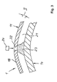
- FIG. 3 shows an embodiment in which the radial fixation of the Inner bow 14 to the jacket bow 11 through a through holes 22 in Sheath bow 11 in the annular space 21 between the inner bow 14 and the Sheath bow 11 introduced quick-curing paste-like mass 23, in particular in the form of fast-curing multi-component concrete Plastic base.
- the holes can 22 by, in particular steel, insert pins 24 are closed.
- the length of the insert pins 24 preferably corresponds to the wall thickness D of the Sheath bow 11.
- the insert pins 24 can be pressed into the bores 22 his. But it is also conceivable that the insert pins 24 with the Jacket elbows 11 are additionally welded. This can be done with a stitching on the outer surface 18 of the jacket sheet 11.
Landscapes
- Engineering & Computer Science (AREA)
- General Engineering & Computer Science (AREA)
- Mechanical Engineering (AREA)
- Civil Engineering (AREA)
- Structural Engineering (AREA)
- Rigid Pipes And Flexible Pipes (AREA)
- Polishing Bodies And Polishing Tools (AREA)
Abstract
Description
- Figur 1
- im vertikalen Längsschnitt einen Rohrbogen;
- Figur 2
- einen Querschnitt durch die Darstellung der Figur 1 in der Ebene II-II in Richtung der Pfeile IIa gesehen;
- Figur 3
- in vergrößertem Maßstab den Ausschnitt III der Figur 1 gemäß einer weiteren Ausführungsform;
- Figur 4
- in vergrößertem Maßstab im vertikalen Längsschnitt einen Kupplungsbund des Rohrbogens der Figur 1;
- Figur 5
- den Ausschnitt V der Figur 4 in vergrößertem Maßstab und
- Figur 6
- den Ausschnitt VI der Figur 4 in vergrößertem Maßstab.
- 1 -
- Rohrbogen
- 2 -
- Kupplungsbunde
- 3 -
- Außenringe von 2
- 4 -
- Innenringe von 2
- 5 -
- Stirnende v. 2
- 6 -
- Steg an 3
- 7 -
- Stirnende v. 2
- 8 -
- Bördelung an 3
- 9 -
- Stirnseite v. 4
- 10 -
- Kupplungsnuten an 3
- 11 -
- Mantelbogen v. 1
- 12 -
- Enden v. 11
- 13 -
- V-Nähte
- 14 -
- Innenbogen v. 1
- 15 -
- Distanzstifte
- 16 -
- Bohrungen f. 15
- 17 -
- äußere Oberfläche v. 14
- 18 -
- äußere Oberfläche v. 11
- 19 -
- endseitiger Innenquerschnitt v. 14
- 20 -
- Innenquerschnitt v. 4
- 21 -
- Ringraum zw. 11 u. 14
- 22 -
- Bohrungen in 11
- 23 -
- pastöse Masse
- 24 -
- Einsatzstifte
- D -
- Wanddicke v. 11
- D1 -
- Wanddicke v. 3
- L -
- axiale Länge v. 2
- PF -
- Pfeil
- QE -
- Querschnittsebenen
- WD -
- Wanddicke v. 4
Claims (10)
- Rohrbogen als Bestandteil eines Rohrstrangs zum Transport von abrasiven Materialien, wie z.B. Sand oder Beton, welcher zwischen zwei endseitigen Kupplungsbunden (2) aus jeweils einem Außenring (3) mit einer umlaufenden äußeren Kupplungsnute (10) und einem im Außenring (3) axial lagefixierten Innenring (4) aus einem gegenüber dem Material des Außenrings (3) verschleißfesteren Material einen mit den beiden Außenringen (3) verschweißten Mantelbogen (11) mit einem Innendurchmesser besitzt, der größer als der Innendurchmesser der Außenringe (3) bemessen ist, und dass sich zwischen den beiden Innenringen (4) im radialen Abstand zum Mantelbogen (11) ein Innenbogen (14) erstreckt, der aus einem gegenüber dem Material des Mantelbogens (11) verschleißfesteren Werkstoff besteht und unter radialer Abstützung am Mantelbogen (11) hinsichtlich seines Innenquerschnitts (19) an beiden Enden zu den Innenquerschnitten (20) der Innenringe (4) koaxial ausgerichtet ist.
- Rohrbogen nach Patentanspruch 1, bei welchem jeder Innenring (4) eines Kupplungsbunds (2) zwischen einem nach innen gerichteten Steg (6) an einem Stirnende (5) des zugeordneten Außenrings (3) und einer mindestens abschnittsweise radial einwärts gerichteten Bördelung (8) am anderen Stirnende (7) eingespannt ist.
- Rohrbogen nach Patentanspruch 1 oder 2, bei welchem der Innenbogen (14) durch Distanzstifte (15) gegenüber dem Mantelbogen (11) radial fixiert ist.
- Rohrbogen nach Patentanspruch 3, bei welchem die Distanzstifte (15) am Mantelbogen (11) durch Schweißung festgelegt sind.
- Rohrbogen nach Patentanspruch 1 oder 2, bei welchem der Innenbogen (14) durch eine über Bohrungen (22) im Mantelbogen (11) in den Ringraum (21) zwischen Innenbogen (14) und Mantelbogen (11) punktuell eingebrachte, schnell aushärtende pastöse Masse (23) gegenüber dem Mantelbogen (11) radial fixiert ist.
- Rohrbogen nach Patentanspruch 5, bei welchem die Bohrungen (22) durch Einsatzstifte (24) verschlossen sind.
- Rohrbogen nach Patentanspruch 6, bei welchem die Einsatzstifte (24) durch Schweißung am Mantelbogen (11) festgelegt sind.
- Rohrbogen nach einem der Patentansprüche 3 bis 7, bei welchem die Distanzstifte (15) oder die Bohrungen (22) zum Einfüllen der pastösen Masse (23) in zwei axial zueinander versetzten Querschnittsebenen (QE) in jeweils 120°-Versetzung vorgesehen sind.
- Rohrbogen nach einem der Patentansprüche 1 bis 8, bei welchem die Außenringe (3) sowie der Mantelbogen (11) aus einem schweißbaren Stahl und die Innenringe (4) sowie der Innenbogen (14) aus Stahlguss bestehen.
- Rohrbogen nach einem der Patentansprüche 1 bis 9, bei welchem der Ringraum (21) zwischen dem Innenbogen (14) und dem Mantelbogen (11) mit einem aushärtenden Kunststoff befüllt ist.
Priority Applications (2)
| Application Number | Priority Date | Filing Date | Title |
|---|---|---|---|
| EP01110710A EP1167858B1 (de) | 2000-07-01 | 2001-05-03 | Rohrbogen zum Transport von abrasiven Materialien |
| US09/884,865 US6494234B2 (en) | 2000-07-01 | 2001-06-19 | Pipe bend for a pipeline for transport of abrasive materials |
Applications Claiming Priority (5)
| Application Number | Priority Date | Filing Date | Title |
|---|---|---|---|
| DE10032074A DE10032074C1 (de) | 2000-07-01 | 2000-07-01 | Rohrbogen als Bestandteil eines Rohrstrangs zum Transport von abrasiven Materialien |
| DE10032074 | 2000-07-01 | ||
| EP00116455 | 2000-07-29 | ||
| EP00116455A EP1167857A3 (de) | 2000-07-01 | 2000-07-29 | Rohrbogen zum Transport von abrasiven Materialien |
| EP01110710A EP1167858B1 (de) | 2000-07-01 | 2001-05-03 | Rohrbogen zum Transport von abrasiven Materialien |
Publications (3)
| Publication Number | Publication Date |
|---|---|
| EP1167858A2 true EP1167858A2 (de) | 2002-01-02 |
| EP1167858A3 EP1167858A3 (de) | 2003-06-04 |
| EP1167858B1 EP1167858B1 (de) | 2004-10-06 |
Family
ID=27213939
Family Applications (1)
| Application Number | Title | Priority Date | Filing Date |
|---|---|---|---|
| EP01110710A Expired - Lifetime EP1167858B1 (de) | 2000-07-01 | 2001-05-03 | Rohrbogen zum Transport von abrasiven Materialien |
Country Status (2)
| Country | Link |
|---|---|
| US (1) | US6494234B2 (de) |
| EP (1) | EP1167858B1 (de) |
Cited By (1)
| Publication number | Priority date | Publication date | Assignee | Title |
|---|---|---|---|---|
| EP3217060A1 (de) * | 2016-03-11 | 2017-09-13 | Centrotherm Systemtechnik GmbH | Doppelrohrbogensystem |
Families Citing this family (20)
| Publication number | Priority date | Publication date | Assignee | Title |
|---|---|---|---|---|
| US6655459B2 (en) * | 2001-07-30 | 2003-12-02 | Weatherford/Lamb, Inc. | Completion apparatus and methods for use in wellbores |
| DE10143290B4 (de) * | 2001-09-04 | 2006-02-09 | Esser-Werke Kg | Bogenförmiges Doppellagenrohr |
| DE10149167A1 (de) * | 2001-10-04 | 2003-04-17 | Endress & Hauser Gmbh & Co Kg | Drei mit einer Schweißverbindung verbundene Bauteile |
| US7073612B2 (en) * | 2004-06-01 | 2006-07-11 | Finchum Ray A | Surge device for air drilling |
| EP1653138A1 (de) * | 2004-10-28 | 2006-05-03 | Esser-Werke KG | Förderrohr für den Feststofftransport |
| DE102005051766B4 (de) * | 2005-10-27 | 2009-02-26 | Esser-Werke Gmbh & Co. Kg | Rohrbogen und Verfahren zur Herstellung eines Rohrbogens |
| DE102006001315B3 (de) * | 2006-01-09 | 2007-05-24 | Esser-Werke Gmbh & Co. Kg | Rohrstrang zum hydraulischen oder pneumatischen Transport von Feststoffen |
| DE602006004860D1 (de) * | 2006-06-28 | 2009-03-05 | Italiana Forme Acciaio | Bogenelement eines Metallrohrmoduls zum Transportieren von Beton oder von anderen stark verschleissenden Materialien im flüssigen Zustand, und Verfahren zur Herstellung eines solchen Elementes |
| DE102006038989B3 (de) * | 2006-08-21 | 2007-12-13 | Esser-Werke Gmbh & Co. Kg | Förderrohr für den Feststofftransport |
| US8282138B2 (en) * | 2008-12-18 | 2012-10-09 | Rostra Tool Company | Crimp ring |
| IT1401515B1 (it) * | 2010-08-03 | 2013-07-26 | Cifa S P A Unico Socio | Procedimento per realizzare un elemento tubolare curvo per il convogliamento di materiali abrasivi quali calcestruzzo, o simili, ed elemento tubolare curvo cosi' ottenuto. |
| US20130174935A1 (en) * | 2012-01-10 | 2013-07-11 | II Curtis R. Patterson | Variable thin walled duct with bend |
| CN105673979B (zh) * | 2015-03-12 | 2018-07-17 | 周朝辉 | 一种两分双层式耐磨抗冲击弯管及其制备方法 |
| CN107580530B (zh) * | 2015-03-20 | 2019-08-27 | 瓦尔姆单一股东有限责任公司 | 用于传输研磨材料的管、用于制造所述管的装置和方法 |
| US10179661B2 (en) * | 2015-11-24 | 2019-01-15 | Hamilton Sundstrand Corporation | Ground connect duct for environmental control systems |
| US10436370B2 (en) * | 2016-04-20 | 2019-10-08 | Georg Fischer Central Plastics Llc | Pipe elbows and methods of manufacture |
| IT201800003964A1 (it) | 2018-03-26 | 2019-09-26 | Valme S R L Unico Socio | Elemento tubolare per il trasferimento di materiali abrasivi, in particolare calcestruzzo, e procedimento per realizzarlo |
| IT201800004795A1 (it) * | 2018-04-23 | 2019-10-23 | Elemento tubolare per il trasferimento di materiali abrasivi, in particolare calcestruzzo, e procedimento per realizzarlo | |
| US11485588B2 (en) * | 2020-03-20 | 2022-11-01 | Cnh Industrial America Llc | Wear resistant granular direction altering device |
| CN117120695A (zh) * | 2021-04-12 | 2023-11-24 | 旭化成贸易株式会社 | 混凝土泵送管 |
Family Cites Families (14)
| Publication number | Priority date | Publication date | Assignee | Title |
|---|---|---|---|---|
| GB1336397A (en) * | 1971-06-25 | 1973-11-07 | Shaw Mcinnes Ltd | Structural elements and a method of producing s'me |
| DE3524757A1 (de) * | 1985-07-11 | 1987-01-22 | Stalter & Grosch Stahlhandel G | Foerderrohr |
| DE3821985C1 (de) * | 1988-06-30 | 1990-03-01 | Metalpraecis Berchem + Schaberg Gesellschaft Fuer Metallformgebung Mbh, 4650 Gelsenkirchen, De | |
| DE4010556A1 (de) * | 1990-04-02 | 1991-10-10 | Esser Brieden Gmbh & Co Kg | Doppellagiger rohrbogen |
| US5379805A (en) * | 1992-12-16 | 1995-01-10 | Construction Forms | Single solid thin wall pipe for abrasive material having a gradual transition in hardness |
| DE19500952C1 (de) * | 1995-01-14 | 1996-07-25 | Esser Werke Gmbh & Co Kg | Rohrbogen |
| DE19500953C1 (de) * | 1995-01-14 | 1996-07-25 | Esser Werke Gmbh & Co Kg | Rohrbogen |
| DE29504332U1 (de) * | 1995-03-14 | 1995-05-11 | Esser-Brieden GmbH & Co KG, 59581 Warstein | Rohr zum Feststofftransport |
| JPH09152087A (ja) * | 1995-11-28 | 1997-06-10 | Naisu Kk | セラミックス製ライニング材及びそれを用いた輸送管のライニング方法 |
| NL1001961C2 (nl) * | 1995-12-21 | 1997-06-24 | Nederland Ptt | Werkwijze voor het installeren van een buizenstelsel met aftakkingen voor telecommunicatiekabels, alsmede een aftakelement voor toepassing bij die werkwijze. |
| DE19736055C1 (de) * | 1997-08-20 | 1998-06-04 | Esser Werke Gmbh & Co Kg | Rohrbogen |
| US6009908A (en) * | 1997-10-30 | 2000-01-04 | Chrysler Corporation | Tube assembly for auxiliary heating and air conditioning system |
| DE19809529C2 (de) * | 1998-03-05 | 2002-12-12 | Esser Werke Gmbh & Co Kg | Transportrohr |
| US6209319B1 (en) * | 1998-09-28 | 2001-04-03 | Honda Giken Kogyo Kabushiki Kaisha | Pipe assembly having inner and outer pipes |
-
2001
- 2001-05-03 EP EP01110710A patent/EP1167858B1/de not_active Expired - Lifetime
- 2001-06-19 US US09/884,865 patent/US6494234B2/en not_active Expired - Fee Related
Cited By (1)
| Publication number | Priority date | Publication date | Assignee | Title |
|---|---|---|---|---|
| EP3217060A1 (de) * | 2016-03-11 | 2017-09-13 | Centrotherm Systemtechnik GmbH | Doppelrohrbogensystem |
Also Published As
| Publication number | Publication date |
|---|---|
| US6494234B2 (en) | 2002-12-17 |
| US20020005222A1 (en) | 2002-01-17 |
| EP1167858A3 (de) | 2003-06-04 |
| EP1167858B1 (de) | 2004-10-06 |
Similar Documents
| Publication | Publication Date | Title |
|---|---|---|
| EP1167858B1 (de) | Rohrbogen zum Transport von abrasiven Materialien | |
| DE10143290B4 (de) | Bogenförmiges Doppellagenrohr | |
| DE69810362T2 (de) | Dichtverbindung zwischen Fluidbohrungen | |
| DE60305180T2 (de) | Rohrkupplung mit einer längsgeteilten muffe | |
| DE2525313C2 (de) | Rohrmuffe | |
| DE3116289A1 (de) | Spanndorn mit einer hydraulisch dehnbaren spannhuelse | |
| DE4010556A1 (de) | Doppellagiger rohrbogen | |
| EP2001779A1 (de) | Transportrohr für dickstoffe | |
| DE2716724B2 (de) | Drehbare Kupplung für eine Vielzahl von Leitungen, insbesondere für eine Boje | |
| WO2008022616A1 (de) | Förderrohr für den feststofftransport | |
| EP1971542B1 (de) | Rohrstrang zum hydraulischen oder pneumatischen transport von feststoffen | |
| EP2177810B1 (de) | Stopfen zum dichten Verschliessen eines Rohres | |
| DE2742118C2 (de) | Verfahren zum Erstellen einer Verschleiß-Schutzanordnung für ein Rohr und Grundkörper für eine Verschleiß-Schutzbüchse zur Ausführung des Verfahrens | |
| DE10021184C2 (de) | Feststofftransportrohr | |
| DE4309680A1 (de) | Vorrichtung zum Innenhochdruckumformen eines rohrförmigen Rohlings | |
| DE10032074C1 (de) | Rohrbogen als Bestandteil eines Rohrstrangs zum Transport von abrasiven Materialien | |
| DE19809529C2 (de) | Transportrohr | |
| DE19607871C2 (de) | Befestigung eines Kupplungsbunds endseitig eines gehärteten Transportrohrs | |
| EP3270027B1 (de) | Rohrleitungsabschnitt mit zwei verbundenen vortriebsrohren | |
| DE3131336A1 (de) | Rohrverteilerstueck fuer vakuum- und gasleitungen | |
| EP1653138A1 (de) | Förderrohr für den Feststofftransport | |
| DE69509445T2 (de) | Spannelement für eine Rohrverbindung | |
| EP2080563A2 (de) | Walze zum Aufnehmen und/oder Übertragen von Leim in Vorrichtungen der Tabak verarbeitenden Industrie | |
| DE202004007321U1 (de) | Verbindung zwischen dem Ende eines gewellten Rohres und einem Anschlußstück | |
| DE2424353A1 (de) | Rohrverbindung sowie verfahren und verbindungshuelse zur herstellung der rohrverbindung |
Legal Events
| Date | Code | Title | Description |
|---|---|---|---|
| PUAI | Public reference made under article 153(3) epc to a published international application that has entered the european phase |
Free format text: ORIGINAL CODE: 0009012 |
|
| AK | Designated contracting states |
Kind code of ref document: A2 Designated state(s): AT BE CH CY DE DK ES FI FR GB GR IE IT LI LU MC NL PT SE TR |
|
| AX | Request for extension of the european patent |
Free format text: AL;LT;LV;MK;RO;SI |
|
| PUAL | Search report despatched |
Free format text: ORIGINAL CODE: 0009013 |
|
| AK | Designated contracting states |
Designated state(s): AT BE CH CY DE DK ES FI FR GB GR IE IT LI LU MC NL PT SE TR |
|
| AX | Request for extension of the european patent |
Extension state: AL LT LV MK RO SI |
|
| 17P | Request for examination filed |
Effective date: 20030502 |
|
| 17Q | First examination report despatched |
Effective date: 20030828 |
|
| AKX | Designation fees paid |
Designated state(s): AT BE CH CY DE DK ES FI FR GB GR IE IT LI LU MC NL PT SE TR |
|
| GRAP | Despatch of communication of intention to grant a patent |
Free format text: ORIGINAL CODE: EPIDOSNIGR1 |
|
| GRAS | Grant fee paid |
Free format text: ORIGINAL CODE: EPIDOSNIGR3 |
|
| GRAA | (expected) grant |
Free format text: ORIGINAL CODE: 0009210 |
|
| AK | Designated contracting states |
Kind code of ref document: B1 Designated state(s): AT BE CH CY DE DK ES FI FR GB GR IE IT LI LU MC NL PT SE TR |
|
| PG25 | Lapsed in a contracting state [announced via postgrant information from national office to epo] |
Ref country code: IT Free format text: LAPSE BECAUSE OF FAILURE TO SUBMIT A TRANSLATION OF THE DESCRIPTION OR TO PAY THE FEE WITHIN THE PRESCRIBED TIME-LIMIT;WARNING: LAPSES OF ITALIAN PATENTS WITH EFFECTIVE DATE BEFORE 2007 MAY HAVE OCCURRED AT ANY TIME BEFORE 2007. THE CORRECT EFFECTIVE DATE MAY BE DIFFERENT FROM THE ONE RECORDED. Effective date: 20041006 Ref country code: TR Free format text: LAPSE BECAUSE OF FAILURE TO SUBMIT A TRANSLATION OF THE DESCRIPTION OR TO PAY THE FEE WITHIN THE PRESCRIBED TIME-LIMIT Effective date: 20041006 Ref country code: IE Free format text: LAPSE BECAUSE OF FAILURE TO SUBMIT A TRANSLATION OF THE DESCRIPTION OR TO PAY THE FEE WITHIN THE PRESCRIBED TIME-LIMIT Effective date: 20041006 Ref country code: NL Free format text: LAPSE BECAUSE OF FAILURE TO SUBMIT A TRANSLATION OF THE DESCRIPTION OR TO PAY THE FEE WITHIN THE PRESCRIBED TIME-LIMIT Effective date: 20041006 Ref country code: FR Free format text: LAPSE BECAUSE OF NON-PAYMENT OF DUE FEES Effective date: 20041006 Ref country code: FI Free format text: LAPSE BECAUSE OF FAILURE TO SUBMIT A TRANSLATION OF THE DESCRIPTION OR TO PAY THE FEE WITHIN THE PRESCRIBED TIME-LIMIT Effective date: 20041006 Ref country code: GB Free format text: LAPSE BECAUSE OF FAILURE TO SUBMIT A TRANSLATION OF THE DESCRIPTION OR TO PAY THE FEE WITHIN THE PRESCRIBED TIME-LIMIT Effective date: 20041006 |
|
| REG | Reference to a national code |
Ref country code: GB Ref legal event code: FG4D Free format text: NOT ENGLISH |
|
| REG | Reference to a national code |
Ref country code: CH Ref legal event code: EP |
|
| REG | Reference to a national code |
Ref country code: IE Ref legal event code: FG4D Free format text: GERMAN |
|
| REF | Corresponds to: |
Ref document number: 50103944 Country of ref document: DE Date of ref document: 20041111 Kind code of ref document: P |
|
| PG25 | Lapsed in a contracting state [announced via postgrant information from national office to epo] |
Ref country code: SE Free format text: LAPSE BECAUSE OF FAILURE TO SUBMIT A TRANSLATION OF THE DESCRIPTION OR TO PAY THE FEE WITHIN THE PRESCRIBED TIME-LIMIT Effective date: 20050106 Ref country code: DK Free format text: LAPSE BECAUSE OF FAILURE TO SUBMIT A TRANSLATION OF THE DESCRIPTION OR TO PAY THE FEE WITHIN THE PRESCRIBED TIME-LIMIT Effective date: 20050106 Ref country code: GR Free format text: LAPSE BECAUSE OF FAILURE TO SUBMIT A TRANSLATION OF THE DESCRIPTION OR TO PAY THE FEE WITHIN THE PRESCRIBED TIME-LIMIT Effective date: 20050106 |
|
| PG25 | Lapsed in a contracting state [announced via postgrant information from national office to epo] |
Ref country code: ES Free format text: LAPSE BECAUSE OF FAILURE TO SUBMIT A TRANSLATION OF THE DESCRIPTION OR TO PAY THE FEE WITHIN THE PRESCRIBED TIME-LIMIT Effective date: 20050117 |
|
| NLV1 | Nl: lapsed or annulled due to failure to fulfill the requirements of art. 29p and 29m of the patents act | ||
| PG25 | Lapsed in a contracting state [announced via postgrant information from national office to epo] |
Ref country code: LU Free format text: LAPSE BECAUSE OF NON-PAYMENT OF DUE FEES Effective date: 20050503 Ref country code: AT Free format text: LAPSE BECAUSE OF NON-PAYMENT OF DUE FEES Effective date: 20050503 Ref country code: CY Free format text: LAPSE BECAUSE OF FAILURE TO SUBMIT A TRANSLATION OF THE DESCRIPTION OR TO PAY THE FEE WITHIN THE PRESCRIBED TIME-LIMIT Effective date: 20050503 |
|
| GBV | Gb: ep patent (uk) treated as always having been void in accordance with gb section 77(7)/1977 [no translation filed] |
Effective date: 20041006 |
|
| REG | Reference to a national code |
Ref country code: IE Ref legal event code: FD4D |
|
| PG25 | Lapsed in a contracting state [announced via postgrant information from national office to epo] |
Ref country code: CH Free format text: LAPSE BECAUSE OF NON-PAYMENT OF DUE FEES Effective date: 20050531 Ref country code: LI Free format text: LAPSE BECAUSE OF NON-PAYMENT OF DUE FEES Effective date: 20050531 Ref country code: BE Free format text: LAPSE BECAUSE OF NON-PAYMENT OF DUE FEES Effective date: 20050531 Ref country code: MC Free format text: LAPSE BECAUSE OF NON-PAYMENT OF DUE FEES Effective date: 20050531 |
|
| PLBE | No opposition filed within time limit |
Free format text: ORIGINAL CODE: 0009261 |
|
| STAA | Information on the status of an ep patent application or granted ep patent |
Free format text: STATUS: NO OPPOSITION FILED WITHIN TIME LIMIT |
|
| 26N | No opposition filed |
Effective date: 20050707 |
|
| EN | Fr: translation not filed | ||
| BERE | Be: lapsed |
Owner name: ESSER -WERKE G.M.B.H. & CO. KG Effective date: 20050531 |
|
| REG | Reference to a national code |
Ref country code: CH Ref legal event code: PL |
|
| BERE | Be: lapsed |
Owner name: *ESSER -WERKE G.M.B.H. & CO. K.G. Effective date: 20050531 |
|
| PG25 | Lapsed in a contracting state [announced via postgrant information from national office to epo] |
Ref country code: PT Free format text: LAPSE BECAUSE OF NON-PAYMENT OF DUE FEES Effective date: 20050306 |
|
| PGFP | Annual fee paid to national office [announced via postgrant information from national office to epo] |
Ref country code: DE Payment date: 20180529 Year of fee payment: 18 |
|
| REG | Reference to a national code |
Ref country code: DE Ref legal event code: R119 Ref document number: 50103944 Country of ref document: DE |
|
| PG25 | Lapsed in a contracting state [announced via postgrant information from national office to epo] |
Ref country code: DE Free format text: LAPSE BECAUSE OF NON-PAYMENT OF DUE FEES Effective date: 20191203 |