EP1167889B1 - Verfahren and Vorrichtung zur Klimatisierung eines Gebäuderaumes - Google Patents
Verfahren and Vorrichtung zur Klimatisierung eines Gebäuderaumes Download PDFInfo
- Publication number
- EP1167889B1 EP1167889B1 EP01401646A EP01401646A EP1167889B1 EP 1167889 B1 EP1167889 B1 EP 1167889B1 EP 01401646 A EP01401646 A EP 01401646A EP 01401646 A EP01401646 A EP 01401646A EP 1167889 B1 EP1167889 B1 EP 1167889B1
- Authority
- EP
- European Patent Office
- Prior art keywords
- air
- room
- ceiling
- false
- volume
- Prior art date
- Legal status (The legal status is an assumption and is not a legal conclusion. Google has not performed a legal analysis and makes no representation as to the accuracy of the status listed.)
- Expired - Lifetime
Links
- 238000000034 method Methods 0.000 title claims abstract description 15
- 238000004378 air conditioning Methods 0.000 title abstract description 6
- 238000002347 injection Methods 0.000 claims description 12
- 239000007924 injection Substances 0.000 claims description 12
- 238000001816 cooling Methods 0.000 claims description 5
- 238000010438 heat treatment Methods 0.000 claims description 5
- 238000000605 extraction Methods 0.000 claims description 4
- 238000005485 electric heating Methods 0.000 claims description 2
- 239000000243 solution Substances 0.000 description 5
- 238000005192 partition Methods 0.000 description 4
- 239000000523 sample Substances 0.000 description 3
- 230000001143 conditioned effect Effects 0.000 description 2
- 230000007423 decrease Effects 0.000 description 2
- 230000003247 decreasing effect Effects 0.000 description 2
- 238000009434 installation Methods 0.000 description 2
- 238000010521 absorption reaction Methods 0.000 description 1
- XAGFODPZIPBFFR-UHFFFAOYSA-N aluminium Chemical compound [Al] XAGFODPZIPBFFR-UHFFFAOYSA-N 0.000 description 1
- 229910052782 aluminium Inorganic materials 0.000 description 1
- 238000009833 condensation Methods 0.000 description 1
- 230000005494 condensation Effects 0.000 description 1
- 235000021183 entrée Nutrition 0.000 description 1
- 238000005259 measurement Methods 0.000 description 1
- 239000011490 mineral wool Substances 0.000 description 1
- 238000005057 refrigeration Methods 0.000 description 1
- 230000001105 regulatory effect Effects 0.000 description 1
- 125000006850 spacer group Chemical group 0.000 description 1
- XLYOFNOQVPJJNP-UHFFFAOYSA-N water Substances O XLYOFNOQVPJJNP-UHFFFAOYSA-N 0.000 description 1
Images

Classifications
-
- F—MECHANICAL ENGINEERING; LIGHTING; HEATING; WEAPONS; BLASTING
- F24—HEATING; RANGES; VENTILATING
- F24F—AIR-CONDITIONING; AIR-HUMIDIFICATION; VENTILATION; USE OF AIR CURRENTS FOR SCREENING
- F24F12/00—Use of energy recovery systems in air conditioning, ventilation or screening
- F24F12/001—Use of energy recovery systems in air conditioning, ventilation or screening with heat-exchange between supplied and exhausted air
- F24F12/006—Use of energy recovery systems in air conditioning, ventilation or screening with heat-exchange between supplied and exhausted air using an air-to-air heat exchanger
-
- E—FIXED CONSTRUCTIONS
- E04—BUILDING
- E04B—GENERAL BUILDING CONSTRUCTIONS; WALLS, e.g. PARTITIONS; ROOFS; FLOORS; CEILINGS; INSULATION OR OTHER PROTECTION OF BUILDINGS
- E04B9/00—Ceilings; Construction of ceilings, e.g. false ceilings; Ceiling construction with regard to insulation
- E04B9/02—Ceilings; Construction of ceilings, e.g. false ceilings; Ceiling construction with regard to insulation having means for ventilation or vapour discharge
-
- F—MECHANICAL ENGINEERING; LIGHTING; HEATING; WEAPONS; BLASTING
- F24—HEATING; RANGES; VENTILATING
- F24F—AIR-CONDITIONING; AIR-HUMIDIFICATION; VENTILATION; USE OF AIR CURRENTS FOR SCREENING
- F24F13/00—Details common to, or for air-conditioning, air-humidification, ventilation or use of air currents for screening
- F24F13/02—Ducting arrangements
- F24F13/06—Outlets for directing or distributing air into rooms or spaces, e.g. ceiling air diffuser
- F24F13/072—Outlets for directing or distributing air into rooms or spaces, e.g. ceiling air diffuser of elongated shape, e.g. between ceiling panels
-
- F—MECHANICAL ENGINEERING; LIGHTING; HEATING; WEAPONS; BLASTING
- F24—HEATING; RANGES; VENTILATING
- F24F—AIR-CONDITIONING; AIR-HUMIDIFICATION; VENTILATION; USE OF AIR CURRENTS FOR SCREENING
- F24F5/00—Air-conditioning systems or apparatus not covered by F24F1/00 or F24F3/00, e.g. using solar heat or combined with household units such as an oven or water heater
- F24F5/0089—Systems using radiation from walls or panels
- F24F5/0092—Systems using radiation from walls or panels ceilings, e.g. cool ceilings
-
- Y—GENERAL TAGGING OF NEW TECHNOLOGICAL DEVELOPMENTS; GENERAL TAGGING OF CROSS-SECTIONAL TECHNOLOGIES SPANNING OVER SEVERAL SECTIONS OF THE IPC; TECHNICAL SUBJECTS COVERED BY FORMER USPC CROSS-REFERENCE ART COLLECTIONS [XRACs] AND DIGESTS
- Y02—TECHNOLOGIES OR APPLICATIONS FOR MITIGATION OR ADAPTATION AGAINST CLIMATE CHANGE
- Y02B—CLIMATE CHANGE MITIGATION TECHNOLOGIES RELATED TO BUILDINGS, e.g. HOUSING, HOUSE APPLIANCES OR RELATED END-USER APPLICATIONS
- Y02B30/00—Energy efficient heating, ventilation or air conditioning [HVAC]
- Y02B30/56—Heat recovery units
Definitions
- the present invention relates to a method of cooling a room or a room building.
- a solution is to have a cooling device directly in the room that blows cold air or produces hot air directly into the room.
- This solution has the disadvantage of not allowing a homogeneous distribution of the temperature in the room, which causes discomfort for people present in the room, and requires the provision of a means of evacuation of the air hot produced by the device when it cools the air.
- this solution requires to install one device per part.
- This last drawback can be eliminated by providing for a single apparatus sending air at the desired temperature in a network of pipes opening into each room to be air conditioned.
- Such device is for example described in documents FR 2 778 228. The result is that this solution does not offer a homogeneous distribution of the temperature which is obviously lower in the vicinity of the mouths introduction of cooled air.
- the air introduced into the false ceiling volume comes from outside the building and has a temperature that is lower than that of the air of the room, and which is similar to that of the air of the room circulating in the volume of false ceiling, the air circulating in the false ceiling volume being introduced into the room when it has reached a substantially equal temperature or slightly lower than that of the air in the room, the method further comprising a step of extracting the air from the room by an extraction opening located at distance from the introductory opening.
- the process according to the invention makes it possible to renew the air in one piece, without calling for a direct opening of the room on outside, for example by a window. This avoids noise problems coming from outside the building.
- the temperature of the coin is decreased both by lowering the temperature of the counterfeit ceiling and by injection into the air room at a slightly temperature less than that of the room. Since heat exchange is at the level of false ceiling, it is carried out remotely from people in the room, this which avoids any embarrassment of these. We also avoid the problems of condensation, because the air injected into the false ceiling volume is previously cooled and heats up while circulating in the false ceiling volume.
- the air injected into the false ceiling volume can be cooled beforehand, if the outside air has a temperature too high compared to the temperature desired in the room.
- the air circulating in the false ceiling volume is heated to means of electric heating plates radiating heat and relatively low power, arranged on the false ceiling, so that the air at level of the introductory opening reaches a substantially equal temperature to that of the air of the room.
- the temperature of the part is advantageously controlled by regulating the flow of air introduced into the false ceiling volume.
- the process according to the invention allows to control the temperature of a room while maintaining a substantially homogeneous distribution in the room.
- the air is introduced into the room tangentially to the false ceiling.
- the invention also relates to a device for carrying out the method according to the invention.
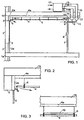
- FIG. 1 shows a part of a building equipped with the device according to the invention, this part being delimited by lower and upper slabs 1a, 1b, and on one side by a front wall 2 and a window 3, and the other by a partition 7.
- the inner faces of the upper slab and the front wall are advantageously covered with thermally insulating layers 2a, 4a.
- the layer 4a covering the ceiling is for example made of mineral wool.
- the ceiling of the room is furthermore equipped with a false ceiling consisting of slabs 4 fixed at a distance from the ceiling, for example by spacers 5, the volume of false ceiling delimited by the upper slab 1b and the false ceiling slabs 4 communicating with the ceiling.
- the volume of the room below by a slot 31 along the inside face of the front wall 2, above the window 3.
- fresh air from outside the building is injected into the false ceiling volume by one or more pipes 10 opening into this volume by the side opposite the slot 31, so that the injected air flows along all the slabs 4 between the pipes 10 and the slot 31.
- This fresh air comes from a central installation 17 for air exchange with the outside, connected to the pipes 10 via a main line 14 and a fresh air circuit 12.
- the device 17 comprises means such as fans to ensure the circulation of air in the circuits 12, 13 and in the building parts. It also includes heat exchange means so as to heat or cool the incoming air with the outgoing air.
- thermostat 8 It is advantageous to have a variable-rate damper the inlet 10 fresh air of each room, so as to control the flow of air introduced into the false ceiling volume according to the gap between a set temperature set by a thermostat 8 and the air temperature ambient in the room measured by a probe associated with the thermostat.
- the thermostat 8 and its probe are preferably arranged in the room on the side of the partition 7.
- a device can be provided refrigeration unit 16 disposed on the main pipe 14.
- FIG. 2 shows in detail the slot 31 for introducing fresh air into the room, between the edge of the false ceiling slabs 4 and the inside face of the front wall 2.
- the slot 31 is hidden by a tongue 6 fixed horizontally on the inner face of the front wall 2, at a short distance e below the slabs 4, so that the air entering the room through the slot 31 follows a substantially horizontal path along the false ceiling .
- the air thus entering the room has a speed of the order of 2 m / s.
- the slot advantageously extends over the entire width of the part, which allows to obtain a high rate of air renewal in the room, of the order of four complete air changes per hour, even with a low speed of introduction of it, and for a standard ceiling height (of the order of 3 m).
- FIG. 3 shows in detail a slab 4 false ceiling, attached to the slab 1b.
- an electric hot plate 19 of low power for example 70 W
- the power supply of the plate 19 can be controlled by the thermostat 8 to control the heating temperature.
- the device described is thus designed to maintain a constant temperature in a building whatever the outside temperature, while ensuring the renewal of the air in the building.
- the outside air When the outside temperature is much higher than the set temperature displayed on the thermostat 8, the outside air is strongly cooled at the level of the main line 14 of external air intake by the device 16, before being injected into the false ceiling volume of the room. Slowly passing along slabs 4 false ceiling, the cold air heats up while cooling the slabs 4. As a result, the air in the room near the slabs 4 cools also. The air then arrives at the slot 31 at a temperature substantially equal to or slightly less than that of the piece.
- FIG. 4 illustrates in the form of curves 21 to 25, the distribution of the temperature in the room, the temperature being given in ordinate as a function of the position of the measurement point in the room, given on the abscissa, going from the window 3 (left in the figure) to partition 7 (right).
- the curve 21 which corresponds to the distribution of the temperature in the false ceiling volume, shows that the air enters the ceiling volume at a temperature around 10 ° C and heats up gradually until to reach a temperature close to 20 ° C in the vicinity of the slot 31.
- the curve 22 gives the distribution of the temperature of the slabs 4, which passes from about 14 ° C to about 20 ° C at the slot 31.
- the curves 23 to 25 give the distribution of the temperature respectively at the height of the ceiling, at mid-height and at the height of the floor of the room. These curves show that the air entering the room is substantially at room temperature, and that the temperature in the room is substantially distributed uniformly between 20 and 23 ° C.
- the device according to the invention allows to ventilate and renew the air of the room.
- the air outside the building is introduced into the ceiling volume without cooling.
- its temperature tends to approach that of the room, and when it reaches level of the slot 31, its temperature is substantially that of the air of the room, or slightly different if there is a difference between the set temperature and the room temperature measured by the probe.
- the 19 heating plates are under electrical tension and gradually heat up cold outside air that passes through the false ceiling volume, so that that it reaches at the slot 31 a substantially identical temperature or slightly different from that of the room, depending on the gap between setpoint temperature and room temperature.
- FIG. 5 shows in the form of curves 26 to 30, the distribution of the temperature in the room, when the outside air is cold, and that the hot plates 19 heat up the air passing through the false ceiling volume.
- the curve 26 which represents the distribution of the temperature in the false ceiling volume, shows that the air enters the false ceiling at low temperature, for example close to 10 ° C, to reach a temperature of 24 ° C at the level of the slot 31.
- the curve 27 gives the distribution of the temperature of the slabs 4 which varies between 14 ° C at the mouth 10 and 24 ° C at the slot 31.
- the curves 28 to 30 give the distribution of the temperature respectively at the height of the ceiling, at mid-height and at the level of the floor of the room. These curves still show that the air entering the room is substantially at room temperature, and that the temperature in the room is substantially distributed uniformly between 20 and 23 ° C.
Landscapes
- Engineering & Computer Science (AREA)
- Chemical & Material Sciences (AREA)
- Combustion & Propulsion (AREA)
- Mechanical Engineering (AREA)
- General Engineering & Computer Science (AREA)
- Sustainable Development (AREA)
- Architecture (AREA)
- Life Sciences & Earth Sciences (AREA)
- Civil Engineering (AREA)
- Structural Engineering (AREA)
- Electromagnetism (AREA)
- Physics & Mathematics (AREA)
- Duct Arrangements (AREA)
- Central Air Conditioning (AREA)
- Air-Conditioning Room Units, And Self-Contained Units In General (AREA)
- Buildings Adapted To Withstand Abnormal External Influences (AREA)
Claims (12)
- Verfahren zum Einstellen der Luft-Temperatur eines Teils eines Gebäudes, welches mit einer falschen Decke versehen ist, umfassend die Schritte:dadurch gekennzeichnet, dass die in das Falsche-Decke-Volumen eingeführte Luft von außerhalb des Gebäudes stammt, und eine Temperatur aufweist, welche geringer ist als diejenige der Luft des Teils, und welche sich beim Zirkulieren in dem Falsche-Decke-Volumen derjenigen der Luft des Teils nähert, wobei die Luft, welche in dem Falsche-Decke-Volumen zirkuliert, in das Teil eingeführt wird, wenn sie eine Temperatur erreicht hat, welche im Wesentlichen gleich zu oder leicht geringer ist als diejenige der Luft des Teils, wobei das Verfahren ferner einen Schritt zur Extraktion von Luft aus dem Teil durch eine Extraktions-Öffnung (9) umfasst, welche mit Abstand zur Einführ-Öffnung angeordnet ist.Injizieren von Luft durch eine Injektions-Öffnung (10) in das durch die Decke (1b) und die falsche Decke (4) des Teils begrenzte Falsche-Decke-Volumen, undEinführen von Luft in das Teil, welche dem Falsche-Decke- Volumen entstammt, durch eine mit Abstand zur Injektions-Öffnung (10) angeordnete Einführ-Öffnung (31),
- Verfahren gemäß Anspruch 1,
dadurch gekennzeichnet, dass zum Absenken der Luft-Temperatur des Teils die in das Falsche-Decke-Volumen injizierte Luft vorab gekühlt wird, wenn die äußere Luft bezüglich der in dem Teil gewünschten Temperatur eine zu hohe Temperatur aufweist. - Verfahren gemäß Anspruch 1 oder 2,
dadurch gekennzeichnet, dass zum Erhöhen der Luft-Temperatur des Teils die Luft, welche in dem Falsche-Decke-Volumen zirkuliert, mittels elektrischer Heizplatten erwärmt wird, welche Wärme abstrahlen und von relativ geringer Leistung sind, und welche an der falschen Decke angeordnet sind, damit die Luft auf Höhe der Einführ-Öffnung eine Temperatur erreichen möge, welche im Wesentlichen gleich ist zu derjenigen der Luft des Teils. - Verfahren gemäß einem der Ansprüche 1 bis 3,
dadurch gekennzeichnet, dass die Temperatur des Teils vorzugsweise mittels Regeln/Steuern der in das Falsche-Decke-Volumen eingeführten Luft-Menge gesteuert ist. - Verfahren gemäß einem der Ansprüche 1 bis 4,
dadurch gekennzeichnet, dass nach Zirkulieren in dem Falsche-Decke-Volumen die Luft in das Teil tangential zur falschen Decke (4) eingeführt wird. - Vorrichtung zum Einstellen der Luft-Temperatur eines Teils eines Gebäudes, umfassend:dadurch gekennzeichnet, dass sie ferner umfasst:eine falschen Decke (4), welche auf Höhe der Decke des Teils ein Falsche-Decke-Volumen begrenzt, und Wärmetausch zwischen dem Falsche-Decke-Volumen und dem Volumen des Teils ermöglicht,eine Öffnung (10) zur Injektion von Luft in das Falsche-Decke-Volumen,eine Öffnung (31) zum Einführen von Luft zwischen dem Falsche-Decke-Volumen und dem Volumen des Teils, welche mit Abstand zur Injektions-Öffnung angeordnet ist,Wärme abstrahlende Heiz-Platten (19) geringer Leistung, welche oberhalb der Oberseite der falschen Decke angeordnet sind,eine Vorrichtung (17) zum Ansaugen von Luft von außerhalb des Gebäudes, welche mit der Injektions-Öffnung (10) verbunden ist,eine Öffnung (9) zur Extraktion von Luft von dem Teil, welche mit Abstand zu der Einführ-Öffnung (31) angeordnet ist.
- Vorrichtung gemäß Anspruch 6,
dadurch gekennzeichnet, dass sie Mittel (16) zum Kühlen von Luft umfasst, welche zwischen der Vorrichtung (17) zum Ansaugen kalter Luft und der Injektions-Öffnung (10) angeordnet sind. - Vorrichtung gemäß Anspruch 6 oder 7,
dadurch gekennzeichnet, dass sie eine Vorrichtung (17) zum Ansaugen von Luft in dem Teil umfasst, welche mit der Extraktions-Öffnung (9) verbunden ist. - Vorrichtung gemäß einem der Ansprüche 6 bis 8,
dadurch gekennzeichnet, dass die Öffnung (31) von einem Schlitz gebildet wird, welcher von einem Rand der falschen Decke (4) und der Innenseite einer Mauer (2) des Gebäudes begrenzt wird. - Vorrichtung gemäß Anspruch 9,
dadurch gekennzeichnet, dass der Schlitz (31) von einer Leiste (6) maskiert ist, welche horizontal an der Innenseite der Mauer (2), dem Schlitz (31) gegenüberliegend, fixiert ist, so dass in das Teil eintretender Luft-Fluss im Wesentlichen horizontal sei. - Vorrichtung gemäß einem der Ansprüche 6 bis 10,
dadurch gekennzeichnet, dass sie eine Vorrichtung (17) zum Wärmetausch zwischen der in das Teil eingeführten kalten Luft und der von dem Teil extrahierten Luft umfasst. - Vorrichtung gemäß einem der Ansprüche 6 bis 11,
dadurch gekennzeichnet, dass die Heiz-Platten (19) in der Nähe der Einführ-Öffnung (31) angeordnet sind.
Applications Claiming Priority (2)
| Application Number | Priority Date | Filing Date | Title |
|---|---|---|---|
| FR0008329A FR2811066B1 (fr) | 2000-06-28 | 2000-06-28 | Procede et dispositif de climatisation d'une piece d'un batiment |
| FR0008329 | 2000-06-28 |
Publications (2)
| Publication Number | Publication Date |
|---|---|
| EP1167889A1 EP1167889A1 (de) | 2002-01-02 |
| EP1167889B1 true EP1167889B1 (de) | 2005-12-21 |
Family
ID=8851810
Family Applications (1)
| Application Number | Title | Priority Date | Filing Date |
|---|---|---|---|
| EP01401646A Expired - Lifetime EP1167889B1 (de) | 2000-06-28 | 2001-06-21 | Verfahren and Vorrichtung zur Klimatisierung eines Gebäuderaumes |
Country Status (4)
| Country | Link |
|---|---|
| EP (1) | EP1167889B1 (de) |
| AT (1) | ATE313768T1 (de) |
| DE (1) | DE60115994D1 (de) |
| FR (1) | FR2811066B1 (de) |
Families Citing this family (4)
| Publication number | Priority date | Publication date | Assignee | Title |
|---|---|---|---|---|
| DE102008054181A1 (de) * | 2008-10-31 | 2010-05-12 | Frenger Systemen BV Heiz- und Kühltechnik GmbH | Klimaeinrichtung |
| DE102009008801A1 (de) * | 2009-02-05 | 2010-08-12 | Bam Deutschland Ag | Bauwerk und Verfahren zum Temperieren und Belüften des Bauwerks |
| FR3006429B1 (fr) * | 2013-06-04 | 2018-02-16 | Hora | Ensemble de plafond et installation de plafond comprenant un tel ensemble de plafond |
| FR3077870B1 (fr) | 2018-02-09 | 2020-12-18 | Ilo | Composant d’un faux-plafond rayonnant modulaire et faux-plafond correspondant. |
Family Cites Families (7)
| Publication number | Priority date | Publication date | Assignee | Title |
|---|---|---|---|---|
| BE528561A (de) * | 1900-01-01 | |||
| BE481366A (de) * | 1900-01-01 | |||
| AU2794789A (en) * | 1987-12-04 | 1989-07-05 | Joseph Rousset | Heat-exchanger for air-conditioning room by low-temperature infrared radiation |
| DE3908108A1 (de) * | 1989-03-13 | 1990-09-20 | Friedrich Dipl Ing Kurr | Grossflaechen-strahlungsheizung fuer decken und waende |
| DE4027833A1 (de) * | 1990-09-03 | 1991-01-31 | Walter Dipl Ing Scheu | Einrichtung und verfahren zur erwaermung oder kuehlung der dem innern von gebaeuden zuzufuehrenden frischluft mit hilfe der erwaermten oder gekuehlten geschossdecken und diesen zugeordneten hohlraeumen |
| TW290624B (de) * | 1995-04-28 | 1996-11-11 | Sanyo Electric Co | |
| FR2778228B1 (fr) * | 1998-05-04 | 2000-10-06 | Robert Ribo | Procede et dispositif de climatisation et/ou de chauffage d'un local comprenant au moins une piece de service et au moins deux pieces principales |
-
2000
- 2000-06-28 FR FR0008329A patent/FR2811066B1/fr not_active Expired - Fee Related
-
2001
- 2001-06-21 EP EP01401646A patent/EP1167889B1/de not_active Expired - Lifetime
- 2001-06-21 DE DE60115994T patent/DE60115994D1/de not_active Expired - Lifetime
- 2001-06-21 AT AT01401646T patent/ATE313768T1/de not_active IP Right Cessation
Also Published As
| Publication number | Publication date |
|---|---|
| EP1167889A1 (de) | 2002-01-02 |
| DE60115994D1 (de) | 2006-01-26 |
| ATE313768T1 (de) | 2006-01-15 |
| FR2811066A1 (fr) | 2002-01-04 |
| FR2811066B1 (fr) | 2002-09-27 |
Similar Documents
| Publication | Publication Date | Title |
|---|---|---|
| EP1999412B1 (de) | Heiz-kühl-und lüftungsverfahren und system eines raumes | |
| US20080176504A1 (en) | Solar heating system and architectural structure with a solar heating system | |
| US8490293B2 (en) | Flat surface dryer | |
| EP1167889B1 (de) | Verfahren and Vorrichtung zur Klimatisierung eines Gebäuderaumes | |
| EP1695010B1 (de) | Heiz- und luftklimatisierungsvorrichtung | |
| JP3273748B2 (ja) | 融雪方法 | |
| JPH05141708A (ja) | 輻射冷暖房パネル | |
| FR2545585A1 (fr) | Perfectionnements a des generateurs de chaleur fonctionnant au gaz et susceptibles d'etre raccordes a une aspiration controlee | |
| FR2473161A1 (fr) | Procede de construction, d'isolation et d'aeration de locaux, et dispositif de ventilation pour sa mise en oeuvre | |
| FR2800853A1 (fr) | Installation de climatisation pour immeubles | |
| FR3136835A1 (fr) | Générateur d’air réversible mobile pour le conditionnement thermique des constructions légères, permanentes ou éphémères | |
| CA1258018A (fr) | Recuperateur de calories a foyer ouvert pour cheminees d'appartement ou de maison individuelle | |
| FR2953001A1 (fr) | Systeme de climatisation. | |
| WO2023099555A1 (fr) | Dispositif émetteur de chaleur ou de froid et système de chauffage ou de rafraichissement intégrant ce dispositif | |
| JP2008281284A (ja) | 建物送風システム及び建物 | |
| FR2516639A1 (fr) | Combine solaire/pompe a chaleur | |
| WO2011128755A2 (fr) | Dispositif thermodynamique pour chauffer et/ou climatiser un batiment | |
| FR2972046A1 (fr) | Installation de chauffage et/ou climatisation d'une piece | |
| FR2706987A1 (en) | Heating installation for heating interiors of churches, in particular of small churches or similar | |
| EP4191146A1 (de) | Umkehrbare doppelstreudecke für strahlungselemente | |
| JPH10185227A (ja) | 空調設備 | |
| JP2000314537A (ja) | 浴室空調機 | |
| CN119826267A (zh) | 一种楼盖内置辐射空调系统及其控制方法 | |
| BE481365A (de) | ||
| FR3139622A1 (fr) | Circuit échangeur de chaleur utilisant les hourdis et Méthode d’installation d’un circuit climatiseur |
Legal Events
| Date | Code | Title | Description |
|---|---|---|---|
| PUAI | Public reference made under article 153(3) epc to a published international application that has entered the european phase |
Free format text: ORIGINAL CODE: 0009012 |
|
| AK | Designated contracting states |
Kind code of ref document: A1 Designated state(s): AT BE CH CY DE DK ES FI FR GB GR IE IT LI LU MC NL PT SE TR |
|
| AX | Request for extension of the european patent |
Free format text: AL;LT;LV;MK;RO;SI |
|
| 17P | Request for examination filed |
Effective date: 20020607 |
|
| AKX | Designation fees paid |
Free format text: AT BE CH CY DE DK ES FI FR GB GR IE IT LI LU MC NL PT SE TR |
|
| 17Q | First examination report despatched |
Effective date: 20040503 |
|
| GRAP | Despatch of communication of intention to grant a patent |
Free format text: ORIGINAL CODE: EPIDOSNIGR1 |
|
| GRAS | Grant fee paid |
Free format text: ORIGINAL CODE: EPIDOSNIGR3 |
|
| GRAA | (expected) grant |
Free format text: ORIGINAL CODE: 0009210 |
|
| AK | Designated contracting states |
Kind code of ref document: B1 Designated state(s): AT BE CH CY DE DK ES FI FR GB GR IE IT LI LU MC NL PT SE TR |
|
| PG25 | Lapsed in a contracting state [announced via postgrant information from national office to epo] |
Ref country code: IT Free format text: LAPSE BECAUSE OF FAILURE TO SUBMIT A TRANSLATION OF THE DESCRIPTION OR TO PAY THE FEE WITHIN THE PRESCRIBED TIME-LIMIT;WARNING: LAPSES OF ITALIAN PATENTS WITH EFFECTIVE DATE BEFORE 2007 MAY HAVE OCCURRED AT ANY TIME BEFORE 2007. THE CORRECT EFFECTIVE DATE MAY BE DIFFERENT FROM THE ONE RECORDED. Effective date: 20051221 Ref country code: NL Free format text: LAPSE BECAUSE OF FAILURE TO SUBMIT A TRANSLATION OF THE DESCRIPTION OR TO PAY THE FEE WITHIN THE PRESCRIBED TIME-LIMIT Effective date: 20051221 Ref country code: GB Free format text: LAPSE BECAUSE OF FAILURE TO SUBMIT A TRANSLATION OF THE DESCRIPTION OR TO PAY THE FEE WITHIN THE PRESCRIBED TIME-LIMIT Effective date: 20051221 Ref country code: IE Free format text: LAPSE BECAUSE OF FAILURE TO SUBMIT A TRANSLATION OF THE DESCRIPTION OR TO PAY THE FEE WITHIN THE PRESCRIBED TIME-LIMIT Effective date: 20051221 Ref country code: FI Free format text: LAPSE BECAUSE OF FAILURE TO SUBMIT A TRANSLATION OF THE DESCRIPTION OR TO PAY THE FEE WITHIN THE PRESCRIBED TIME-LIMIT Effective date: 20051221 Ref country code: AT Free format text: LAPSE BECAUSE OF FAILURE TO SUBMIT A TRANSLATION OF THE DESCRIPTION OR TO PAY THE FEE WITHIN THE PRESCRIBED TIME-LIMIT Effective date: 20051221 |
|
| REG | Reference to a national code |
Ref country code: GB Ref legal event code: FG4D Free format text: NOT ENGLISH |
|
| REG | Reference to a national code |
Ref country code: CH Ref legal event code: EP |
|
| REG | Reference to a national code |
Ref country code: IE Ref legal event code: FG4D Free format text: LANGUAGE OF EP DOCUMENT: FRENCH |
|
| REF | Corresponds to: |
Ref document number: 60115994 Country of ref document: DE Date of ref document: 20060126 Kind code of ref document: P |
|
| PG25 | Lapsed in a contracting state [announced via postgrant information from national office to epo] |
Ref country code: SE Free format text: LAPSE BECAUSE OF FAILURE TO SUBMIT A TRANSLATION OF THE DESCRIPTION OR TO PAY THE FEE WITHIN THE PRESCRIBED TIME-LIMIT Effective date: 20060321 Ref country code: GR Free format text: LAPSE BECAUSE OF FAILURE TO SUBMIT A TRANSLATION OF THE DESCRIPTION OR TO PAY THE FEE WITHIN THE PRESCRIBED TIME-LIMIT Effective date: 20060321 Ref country code: DK Free format text: LAPSE BECAUSE OF FAILURE TO SUBMIT A TRANSLATION OF THE DESCRIPTION OR TO PAY THE FEE WITHIN THE PRESCRIBED TIME-LIMIT Effective date: 20060321 |
|
| PG25 | Lapsed in a contracting state [announced via postgrant information from national office to epo] |
Ref country code: DE Free format text: LAPSE BECAUSE OF FAILURE TO SUBMIT A TRANSLATION OF THE DESCRIPTION OR TO PAY THE FEE WITHIN THE PRESCRIBED TIME-LIMIT Effective date: 20060322 |
|
| PG25 | Lapsed in a contracting state [announced via postgrant information from national office to epo] |
Ref country code: ES Free format text: LAPSE BECAUSE OF FAILURE TO SUBMIT A TRANSLATION OF THE DESCRIPTION OR TO PAY THE FEE WITHIN THE PRESCRIBED TIME-LIMIT Effective date: 20060401 |
|
| PG25 | Lapsed in a contracting state [announced via postgrant information from national office to epo] |
Ref country code: PT Free format text: LAPSE BECAUSE OF FAILURE TO SUBMIT A TRANSLATION OF THE DESCRIPTION OR TO PAY THE FEE WITHIN THE PRESCRIBED TIME-LIMIT Effective date: 20060522 |
|
| NLV1 | Nl: lapsed or annulled due to failure to fulfill the requirements of art. 29p and 29m of the patents act | ||
| REG | Reference to a national code |
Ref country code: FR Ref legal event code: CA |
|
| PG25 | Lapsed in a contracting state [announced via postgrant information from national office to epo] |
Ref country code: MC Free format text: LAPSE BECAUSE OF NON-PAYMENT OF DUE FEES Effective date: 20060630 Ref country code: LI Free format text: LAPSE BECAUSE OF NON-PAYMENT OF DUE FEES Effective date: 20060630 Ref country code: BE Free format text: LAPSE BECAUSE OF NON-PAYMENT OF DUE FEES Effective date: 20060630 Ref country code: CH Free format text: LAPSE BECAUSE OF NON-PAYMENT OF DUE FEES Effective date: 20060630 |
|
| GBV | Gb: ep patent (uk) treated as always having been void in accordance with gb section 77(7)/1977 [no translation filed] |
Effective date: 20051221 |
|
| REG | Reference to a national code |
Ref country code: IE Ref legal event code: FD4D |
|
| PLBE | No opposition filed within time limit |
Free format text: ORIGINAL CODE: 0009261 |
|
| STAA | Information on the status of an ep patent application or granted ep patent |
Free format text: STATUS: NO OPPOSITION FILED WITHIN TIME LIMIT |
|
| 26N | No opposition filed |
Effective date: 20060922 |
|
| REG | Reference to a national code |
Ref country code: CH Ref legal event code: PL |
|
| BERE | Be: lapsed |
Owner name: HORA Effective date: 20060630 |
|
| PG25 | Lapsed in a contracting state [announced via postgrant information from national office to epo] |
Ref country code: TR Free format text: LAPSE BECAUSE OF FAILURE TO SUBMIT A TRANSLATION OF THE DESCRIPTION OR TO PAY THE FEE WITHIN THE PRESCRIBED TIME-LIMIT Effective date: 20051221 Ref country code: LU Free format text: LAPSE BECAUSE OF NON-PAYMENT OF DUE FEES Effective date: 20060621 |
|
| PG25 | Lapsed in a contracting state [announced via postgrant information from national office to epo] |
Ref country code: CY Free format text: LAPSE BECAUSE OF FAILURE TO SUBMIT A TRANSLATION OF THE DESCRIPTION OR TO PAY THE FEE WITHIN THE PRESCRIBED TIME-LIMIT Effective date: 20051221 |
|
| REG | Reference to a national code |
Ref country code: FR Ref legal event code: ST Effective date: 20100226 |
|
| PG25 | Lapsed in a contracting state [announced via postgrant information from national office to epo] |
Ref country code: FR Free format text: LAPSE BECAUSE OF NON-PAYMENT OF DUE FEES Effective date: 20090630 |
|
| REG | Reference to a national code |
Ref country code: FR Ref legal event code: RN |
|
| REG | Reference to a national code |
Ref country code: FR Ref legal event code: D3 |
|
| PGRI | Patent reinstated in contracting state [announced from national office to epo] |
Ref country code: FR Effective date: 20100617 |
|
| REG | Reference to a national code |
Ref country code: FR Ref legal event code: PLFP Year of fee payment: 16 |
|
| REG | Reference to a national code |
Ref country code: FR Ref legal event code: PLFP Year of fee payment: 17 |
|
| REG | Reference to a national code |
Ref country code: FR Ref legal event code: CA Effective date: 20170619 |
|
| REG | Reference to a national code |
Ref country code: FR Ref legal event code: PLFP Year of fee payment: 18 |
|
| PGFP | Annual fee paid to national office [announced via postgrant information from national office to epo] |
Ref country code: FR Payment date: 20190625 Year of fee payment: 19 |
|
| PG25 | Lapsed in a contracting state [announced via postgrant information from national office to epo] |
Ref country code: FR Free format text: LAPSE BECAUSE OF NON-PAYMENT OF DUE FEES Effective date: 20200630 |