EP1167910A2 - Condenser - Google Patents
Condenser Download PDFInfo
- Publication number
- EP1167910A2 EP1167910A2 EP01115028A EP01115028A EP1167910A2 EP 1167910 A2 EP1167910 A2 EP 1167910A2 EP 01115028 A EP01115028 A EP 01115028A EP 01115028 A EP01115028 A EP 01115028A EP 1167910 A2 EP1167910 A2 EP 1167910A2
- Authority
- EP
- European Patent Office
- Prior art keywords
- path
- paths
- refrigerant
- cross
- sectional area
- Prior art date
- Legal status (The legal status is an assumption and is not a legal conclusion. Google has not performed a legal analysis and makes no representation as to the accuracy of the status listed.)
- Granted
Links
Images




Classifications
-
- F—MECHANICAL ENGINEERING; LIGHTING; HEATING; WEAPONS; BLASTING
- F28—HEAT EXCHANGE IN GENERAL
- F28F—DETAILS OF HEAT-EXCHANGE AND HEAT-TRANSFER APPARATUS, OF GENERAL APPLICATION
- F28F9/00—Casings; Header boxes; Auxiliary supports for elements; Auxiliary members within casings
- F28F9/02—Header boxes; End plates
- F28F9/0202—Header boxes having their inner space divided by partitions
- F28F9/0204—Header boxes having their inner space divided by partitions for elongated header box, e.g. with transversal and longitudinal partitions
- F28F9/0209—Header boxes having their inner space divided by partitions for elongated header box, e.g. with transversal and longitudinal partitions having only transversal partitions
- F28F9/0212—Header boxes having their inner space divided by partitions for elongated header box, e.g. with transversal and longitudinal partitions having only transversal partitions the partitions being separate elements attached to header boxes
-
- F—MECHANICAL ENGINEERING; LIGHTING; HEATING; WEAPONS; BLASTING
- F25—REFRIGERATION OR COOLING; COMBINED HEATING AND REFRIGERATION SYSTEMS; HEAT PUMP SYSTEMS; MANUFACTURE OR STORAGE OF ICE; LIQUEFACTION SOLIDIFICATION OF GASES
- F25B—REFRIGERATION MACHINES, PLANTS OR SYSTEMS; COMBINED HEATING AND REFRIGERATION SYSTEMS; HEAT PUMP SYSTEMS
- F25B39/00—Evaporators; Condensers
- F25B39/04—Condensers
-
- F—MECHANICAL ENGINEERING; LIGHTING; HEATING; WEAPONS; BLASTING
- F28—HEAT EXCHANGE IN GENERAL
- F28D—HEAT-EXCHANGE APPARATUS, NOT PROVIDED FOR IN ANOTHER SUBCLASS, IN WHICH THE HEAT-EXCHANGE MEDIA DO NOT COME INTO DIRECT CONTACT
- F28D1/00—Heat-exchange apparatus having stationary conduit assemblies for one heat-exchange medium only, the media being in contact with different sides of the conduit wall, in which the other heat-exchange medium is a large body of fluid, e.g. domestic or motor car radiators
- F28D1/02—Heat-exchange apparatus having stationary conduit assemblies for one heat-exchange medium only, the media being in contact with different sides of the conduit wall, in which the other heat-exchange medium is a large body of fluid, e.g. domestic or motor car radiators with heat-exchange conduits immersed in the body of fluid
- F28D1/04—Heat-exchange apparatus having stationary conduit assemblies for one heat-exchange medium only, the media being in contact with different sides of the conduit wall, in which the other heat-exchange medium is a large body of fluid, e.g. domestic or motor car radiators with heat-exchange conduits immersed in the body of fluid with tubular conduits
- F28D1/053—Heat-exchange apparatus having stationary conduit assemblies for one heat-exchange medium only, the media being in contact with different sides of the conduit wall, in which the other heat-exchange medium is a large body of fluid, e.g. domestic or motor car radiators with heat-exchange conduits immersed in the body of fluid with tubular conduits the conduits being straight
- F28D1/0535—Heat-exchange apparatus having stationary conduit assemblies for one heat-exchange medium only, the media being in contact with different sides of the conduit wall, in which the other heat-exchange medium is a large body of fluid, e.g. domestic or motor car radiators with heat-exchange conduits immersed in the body of fluid with tubular conduits the conduits being straight the conduits having a non-circular cross-section
- F28D1/05366—Assemblies of conduits connected to common headers, e.g. core type radiators
- F28D1/05375—Assemblies of conduits connected to common headers, e.g. core type radiators with particular pattern of flow, e.g. change of flow direction
-
- F—MECHANICAL ENGINEERING; LIGHTING; HEATING; WEAPONS; BLASTING
- F25—REFRIGERATION OR COOLING; COMBINED HEATING AND REFRIGERATION SYSTEMS; HEAT PUMP SYSTEMS; MANUFACTURE OR STORAGE OF ICE; LIQUEFACTION SOLIDIFICATION OF GASES
- F25B—REFRIGERATION MACHINES, PLANTS OR SYSTEMS; COMBINED HEATING AND REFRIGERATION SYSTEMS; HEAT PUMP SYSTEMS
- F25B2500/00—Problems to be solved
- F25B2500/01—Geometry problems, e.g. for reducing size
-
- F—MECHANICAL ENGINEERING; LIGHTING; HEATING; WEAPONS; BLASTING
- F28—HEAT EXCHANGE IN GENERAL
- F28D—HEAT-EXCHANGE APPARATUS, NOT PROVIDED FOR IN ANOTHER SUBCLASS, IN WHICH THE HEAT-EXCHANGE MEDIA DO NOT COME INTO DIRECT CONTACT
- F28D21/00—Heat-exchange apparatus not covered by any of the groups F28D1/00 - F28D20/00
- F28D2021/0019—Other heat exchangers for particular applications; Heat exchange systems not otherwise provided for
- F28D2021/008—Other heat exchangers for particular applications; Heat exchange systems not otherwise provided for for vehicles
- F28D2021/0084—Condensers
Definitions
- the present invention relates to a condenser suitably used for, for example, a refrigeration system for car air-conditioners.
- a conventional multi-flow type condenser for use in car air-conditioners includes a pair of vertical headers 1 and 1 disposed apart from each other and a plurality of horizontal flat tubes 2 as heat exchanging tubes disposed between the headers at certain intervals in the direction of up-and-down with their opposite ends connected with the headers.
- One of the headers 1 is provided with a refrigerant inlet 1a at the upper end portion thereof, and the other header 1 is provided with a refrigerant outlet 1b at the lower portion thereof.
- the headers 1 are provided with partitions 5 each disposed at a predetermined portion for dividing the inside of the header to thereby group the aforementioned plurality of flat tubes 2 into a plurality of paths P1 to P3.
- the refrigerant introduced from the refrigerant inlet 1a passes downwardly through each path P1 to P3 in sequence in a meandering manner, and then flows out of the refrigerant outlet 1b.
- the refrigerant exchanges heat with the ambient air to be condensed into a liquefied refrigerant.
- the inventors of the present application analyzed the stagnation of the liquefied refrigerant in the aforementioned condenser by using a thermography. According to the results of the analysis, as shown in Figs. 9 and 10, the liquefied refrigerant RL tends to stagnate at the downstream lower portion in each path P1-P3.
- the liquefied refrigerant RL tends to stagnate at the downstream lower portion in each path P1-P3.
- the liquefaction of refrigerant has already started at the end portion in the first path P1. Therefore, the liquefied refrigerant RL stays at the bottom of the header portion connecting the first and second paths P1 and P2, which may cause the so-called liquid stagnation.
- the liquefied refrigerant RL impedes the refrigerant circulation, resulting in an increased refrigerant flow resistance.
- a condenser includes a pair of right and left headers, a plurality of heat exchanging tubes disposed between the headers with opposite ends thereof connected with the headers, at least one partition provided in one of the headers to group the plurality of heat exchanging tubes into a plurality of paths, a refrigerant inlet provided at a lower portion of one of the headers and a refrigerant outlet provided at an upper portion of one of the headers.
- a refrigerant introduced from the refrigerant inlet passes upwardly through the plurality of paths in sequence in a meandering manner, and flows out of the refrigerant outlet.
- a cross-sectional area of each of the paths decreases stepwise towards a downstream side of the paths for each path, and that a reduction rate of a cross-sectional area of a downstream side path of adjacent two paths to a cross-sectional area of an upstream side path thereof is 20% or more.
- the gaseous refrigerant flowed out of the heat exchanging tubes constituting the upstream side path goes up vigorously in the refrigerant turning portion of the header connecting the adjacent paths, and the rising refrigerant flows into the heat exchanging tubes constituting the downstream side path (upper side path).
- the liquefied refrigerant is pushed up by the blow-up effect of this rising refrigerant, and flows into the heat exchanging tubes constituting the downstream side path (upper side path) smoothly. This prevents a stagnation of the liquefied refrigerant, which keeps a large effective heat transferring area of the heat exchanging portion and enables an equally distributed smooth refrigerant flow in each path.
- the plurality of paths is comprised of three or more paths including a first path, a second path and a third path through which the refrigerant introduced from the refrigerant inlet passes in sequence, a reduction rate of a cross-sectional area of the second path to a cross-sectional area of the first path is 50% or more, and a reduction rate of a cross-sectional area of the third path to a cross-sectional area of the second path is 40% or more.
- the aforementioned refrigerant blow-up effect by the refrigerant turning portion connecting the adjacent paths can fully be obtained, which can assuredly prevent the stagnation of the liquefied refrigerant in the refrigerant turning portion.
- a condenser includes a plurality of paths arranged one on the other, each of the paths including a plurality of heat exchanging tubes, a header portion connected to corresponding ends of adjacent upper and lower paths, a refrigerant inlet provided at a lowermost path; and a refrigerant outlet provided at an uppermost path.
- a refrigerant introduced from the refrigerant inlet goes upwardly from the lowermost path towards the uppermost path while making a U-turn in the header portion, and flows out of the refrigerant outlet.
- a reduction rate of a cross-sectional area of a downstream side path of adjacent two paths to a cross-sectional area of an upstream side path thereof is 20% or more.
- the liquefied refrigerant is pushed up by the blow-up effect of the rising refrigerant, and flows into the heat exchanging tubes constituting the downstream side path (upper side path) smoothly.
- This prevents a stagnation of the liquefied refrigerant which keeps a large effective heat transferring area of the heat exchanging portion and enables an equally distributed smooth refrigerant flow in each path.
- a condenser includes a first header portion with a refrigerant inlet, a lowermost first path including a plurality of heat exchanging tubes whose one end being connected with the first header portion, a final header portion with a refrigerant outlet, an uppermost final path including a plurality of heat exchanging tubes whose one end being connected with the final header portion, one or a plurality of middle paths each including a plurality of heat exchanging tubes, and a plurality of middle header portions each connecting corresponding one ends of adjacent paths.
- a refrigerant introduced from the refrigerant inlet flows upwardly through the plurality of paths in sequence in a meandering manner via each of the header portions, and flows out of the refrigerant.
- a reduction rate of a cross-sectional area of a downstream side path of adjacent two paths to a cross-sectional area of an upstream side path thereof is 20% or more.
- Fig. 1 is a front view showing a condenser for use in car air-conditioners according to an embodiment of the present invention
- Fig. 2 is a schematic front view showing a refrigerant circuit arrangement of the condenser according to the embodiment
- Fig. 3 is an enlarged cross-sectional view showing a first refrigerant turning portion and therearound of the condenser according to the embodiment
- Fig. 4 is a schematic cross-sectional view showing a refrigerant circuit arrangement of a condenser for use in car air-conditioners according to a second embodiment of the present invention
- Fig. 5 is a schematic cross-sectional view showing a refrigerant circuit arrangement of a condenser for use in car air-conditioners according to a third embodiment of the present invention
- Fig. 6 is a schematic cross-sectional view showing a refrigerant circuit arrangement of a condenser for use in car air-conditioners according to a comparative example
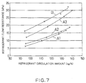
- Fig. 7 is a graph showing a relationship between a refrigerant flow resistance and a refrigerant circulation amount of the inventive and comparative condensers;
- Fig. 8 is a partially omitted front view showing a conventional condenser for use in car air-conditioners
- Fig. 9 is a schematic front view showing a refrigerant circuit arrangement of the conventional condenser.
- Fig. 10 is a schematic cross-sectional view showing a first refrigerant turning portion and therearound of the conventional condenser.
- Figs. 1 and 2 show a multi-flow type condenser for use in car air-conditioners according to an embodiment of the present invention.
- this condenser has a pair of right and left headers 11 and 11 disposed at a certain distance. Between these headers 11 and 11, a plurality of flat tubes 12 as heat exchanging tubes are horizontally disposed at certain intervals in the vertical direction with their opposites ends connected to the headers 11 and 11. Furthermore, corrugate fins 13 are arranged between adjacent flat tubes 12 and disposed on the outermost flat tubes 12. Furthermore, on the outside of each outermost corrugate fin 13, a belt-shaped side plate 14 is disposed for protecting the outermost corrugated fin 13.
- a refrigerant inlet 11a is provided at the lower side of one of headers 11 (right header).
- a refrigerant outlet 11b is provided at the upper side of the other header 11 (left header).
- each header 11 a partition 16 which divides the interior of the header 11 in the longitudinal direction thereof is provided, to thereby group the aforementioned plurality of flat tubes 12 into three paths, the first path P1 (lowermost path), the second path P2 (middle path) and the third path P3 (uppermost path).
- the header portion of the left header 11 which connects the first path P1 with the second paths P1 and P2 constitutes a first refrigerant turning portion T1
- the header portion of the right header 11 which connects the second P2 with the third paths P3 constitutes a second refrigerant turning portion T2.
- each header portion constituting the turning portion T1 and T2 may be formed by a separate individual header pipe.
- each path P1-P3 is decreased in cross-sectional area stepwise towards the downstream side path (upper side path) for each path.
- the reduction rate of the cross-sectional area of the downstream side path (upper side path) of the two adjacent paths to the upstream side path (lower side path) thereof should be set to 20% or more, and it is preferable that the reduction rate is set to 30% or more.
- the aforementioned reduction rate (%) can be obtained by the following formula: (1-PL/PU)x100(%), where "PU” is a cross-sectional area of the upstream side path and "PL" is that of the downstream side path.
- the aforementioned reduction rate is set to 25% or more in any two adjacent paths. It is more preferable that the reduction rate of the cross-sectional area of the second path to the cross-sectional area of the first path is 50% or more and that the reduction rate of the cross-sectional area of the third path to the cross-sectional area of the second path is 40% or more.
- the condenser of this embodiment all of the flat tubes 12 have the same structure, and therefore the cross-sectional area of each path P1-P3 is in proportion to the number of tubes of each path P1-P3. Therefore, the reduction rate of the cross-sectional area between adjacent paths corresponds to the reduction rate of the number of tubes between the adjacent paths.
- the first path P1 includes 22 flat tubes
- the second path P2 includes 9 flat tubes
- the third path P3 includes 5 flat tubes. Accordingly, the reduction rate of the cross-sectional areas between the first and second paths P1 and P2 is 59.1%, and that between the second and third paths P2 and P3 is 44.4%.
- the reduction rate of the cross-sectional areas between adjacent paths may be set such that each path is constituted by the same number of tubes having different cross-sectional area.
- the total number of the paths is not especially limited, it is preferable that the total number is set to 2 to 5, more preferably 3 or 4. The most suitable total number is 3. If the total number of paths is set too much, the reduction rate of the cross-sectional areas between adjacent paths, i.e., the reduction rate of the tube number between the adjacent paths in the aforementioned embodiment, becomes too small, which causes a trouble in securing the aforementioned reduction rate. Thus, an effective refrigerant blow-up effect may not be obtained.
- the cross-sectional area of each path is decreased stepwise for every path towards the downstream side (upper side).
- the heat exchange core may include adjacent paths each having the same cross-sectional area. Therefore, it should be understood that the present invention covers such a condenser including adjacent paths each having the same cross-sectional area, unless otherwise clearly defined.
- the refrigerant introduced from the refrigerant inlet 11a passes upwardly through the first to third paths P1-P3 in sequence in a meandering manner, and flows out of the refrigerant outlet 11b. While passing through these paths, the refrigerant exchanges heat with the ambient air to be gradually condensed and liquefied.
- the liquefaction of the gaseous refrigerant introduced from the refrigerant inlet 11a starts at the end portion of the first path P1, for example, and the liquefied refrigerant RL flows out of the tube-outlets of the first path P1 and tends to flow downwards in the first refrigerant turning portion T1, as shown in Fig 3.
- the gaseous refrigerant RG flows out of the tube-outlets of the first path P1, and goes up vigorously in the first turning portion T1. This rising gaseous refrigerant RG pushes up the aforementioned liquefied refrigerant RL.
- the liquefied refrigerant RL goes up in the first refrigerant turning portion T1 together with the gaseous refrigerant RG, and this rising mixture of refrigerant will be evenly distributed into each flat tube 12 constituting the second path P2 smoothly.
- the cross-sectional area of the second path P2 is set to the aforementioned specific reduction rate to that of the first path P1
- the flow velocity of the gaseous refrigerant rising in the first refrigerant turning portion T1 between the first and second paths P1 and P2 can be secured enough. Therefore, a sufficient blow-up effect in the refrigerant turning portion T1 can be obtained by the rising refrigerant, which in turn can prevent assuredly the stagnation of the liquefied refrigerant RL in the bottom portion of the refrigerant turning portion T1.
- the whole core surface can be used effectively as a heat exchanging portion, resulting in an improved cooling performance.
- the refrigerant will not stagnate and will pass through the whole region of each path in an evenly distributed manner, the refrigerant flow resistance can be reduced, resulting in a further enhanced heat exchanging performance.
- a condenser was manufactured in accordance with the aforementioned embodiment shown in Figs. 1 and 2.
- This condenser has three paths, i.e., the lowermost first path P1, the middle second path P2 and the uppermost third path P3.
- the first, second and third paths P1, P2 and P3 include twenty-two (22) tubes, nine (9) tubes and five (5) tubes, respectively.
- the reduction rate of the cross-sectional area of the second path P2 to that of the first path P1 is 59.1%
- the reduction rate of the cross-sectional area of the third path P3 to that of the second path P2 is 44.4%
- a condenser having three paths i.e., the lowermost first path P1, the middle second path P2 and the uppermost third path P3, was manufactured.
- the first, second and third paths P1, P2 and P3 include eighteen (18) tubes, nine (9) tubes and five (5) tubes, respectively.
- Another structure is the same as the condenser of the first example. In this condenser, the reduction rate of the cross-sectional area of the second path P2 to that of the first path P1 is 50%, and the reduction rate of the cross-sectional area of the third path P3 to that of the second path P2 is 44.4%
- a condenser having four paths i.e.. the lowermost first path P1, the lower middle second path P2, the upper middle third path P3 and the uppermost fourth path P4, was manufactured.
- the first, second, third and fourth paths P1, P2, P3 and P4 include thirteen (13) tubes, nine (9) tubes, six (6) tubes and four (4) tubes, respectively.
- Another structure is the same as the condenser of the first example.
- the reduction rate of the cross-sectional area of the second path P2 to that of the first path P1 is 30.8%
- the reduction rate of the cross-sectional area of the third path P3 to that of the second path P2 is 33.3%
- the reduction rate of the cross-sectional area of the fourth path P4 to that of the third path P3 is 33.3%.
- the reference numeral T4 denotes a fourth refrigerant turning portion (the same numeral will be used in Fig. 6)
- a condenser having four paths i.e., the uppermost first path P1, the upper middle second path P2, the lower middle third path P3 and the lowermost fourth path P4, was manufactured.
- the first, second, third and fourth paths P1, P2, P3 and P4 include thirteen (13) tubes, nine (9) tubes, six (6) tubes and four (4) tubes, respectively.
- Another structure is the same as the condenser of the first example.
- This condenser according to the comparative example has a symmetrical configuration rotated by 180 degrees to the aforementioned condenser according to the third example.
- the reduction rate of the cross-sectional area of the second path P2 to that of the first path P1 is 30.8%
- the reduction rate of the cross-sectional area of the third path P3 to that of the second path P2 is 33.3%
- the reduction rate of the cross-sectional area of the fourth path P4 to that of the third path P3 is 33.3%.
- the first and second examples A1 and A2 were able to reduce flow resistance remarkably.
- the reason is considered as follows: since the reduction rate of the cross-sectional area of the second path P2 to the cross-sectional area of the first path P1 is set to 50% or more and the reduction rate of the cross-sectional area of the third path P3 to the cross-sectional area of the second path P2 is set to 40% or more, the refrigerant blow-up effect between adjacent paths could fully be obtained and therefore the circulation of the refrigerant could be performed much more smoothly.
Landscapes
- Engineering & Computer Science (AREA)
- Physics & Mathematics (AREA)
- Mechanical Engineering (AREA)
- Thermal Sciences (AREA)
- General Engineering & Computer Science (AREA)
- Heat-Exchange Devices With Radiators And Conduit Assemblies (AREA)
- Air-Conditioning For Vehicles (AREA)
- Oscillators With Electromechanical Resonators (AREA)
- Valve Device For Special Equipments (AREA)
Abstract
Description
Claims (9)
- A condenser, comprising:a pair of right and left headers;a plurality of heat exchanging tubes disposed between said headers with opposite ends thereof connected with said headers;at least one partition provided in one of said headers to group said plurality of heat exchanging tubes into a plurality of paths;a refrigerant inlet provided at a lower portion of one of said headers; anda refrigerant outlet provided at an upper portion of one of said headers;wherein a refrigerant introduced from said refrigerant inlet passes upwardly through said plurality of paths in sequence in a meandering manner, and flows out of said refrigerant outlet,wherein a cross-sectional area of each of said paths decreases stepwise towards a downstream side of said paths for each path, andwherein a reduction rate of a cross-sectional area of a downstream side path of adjacent two paths to a cross-sectional area of an upstream side path thereof is 20% or more.
- The condenser as recited in claim 1, wherein said headers are disposed vertically, and wherein said plurality of heat exchanging tubes are disposed horizontally at predetermined intervals.
- The condenser as recited in claim 2, wherein said cross-sectional area of said downstream side path is smaller than that of said upstream side path in any adjacent two paths.
- The condenser as recited in claim 1 or 8, wherein said plurality of heat exchanging tubes are grouped into 2 to 5 paths or into 3 paths.
- A condenser, comprising:a plurality of paths arranged one on the other, each of said paths including a plurality of heat exchanging tubes;a header portion connected to corresponding ends of adjacent upper and lower paths;a refrigerant inlet provided at a lowermost path; anda refrigerant outlet provided at an uppermost path,wherein a refrigerant introduced from said refrigerant inlet goes upwardly from said lowermost path towards said uppermost path while making a U-turn in said header portion, and flows out of said refrigerant outlet, andwherein a reduction rate of a cross-sectional area of a downstream side path of adjacent two paths to a cross-sectional area of an upstream side path thereof is 20% or more.
- The condenser as recited in claim 5 or 8, wherein said plurality of paths are 2 to 5 paths or are 3 paths.
- A condenser, comprising:a first header portion with a refrigerant inlet;a lowermost first path including a plurality of heat exchanging tubes whose one end being connected with said first header portion;a final header portion with a refrigerant outlet;an uppermost final path including a plurality of heat exchanging tubes whose one end being connected with said final header portion;one or a plurality of middle paths each including a plurality of heat exchanging tubes; anda plurality of middle header portions each connecting corresponding one ends of adjacent paths,wherein a refrigerant introduced from said refrigerant inlet flows upwards through said plurality of paths in sequence in a meandering manner via each of said header portions, and flows out of said refrigerant, andwherein a reduction rate of a cross-sectional area of a downstream side path of adjacent two paths to a cross-sectional area of a upstream side path thereof is 20% or more.
- The condenser as recited in claim 1 or 2 or 5 or 7, wherein said plurality of paths include three or more paths including a first path, a second path and a third path through which said refrigerant introduced from said refrigerant inlet passes in sequence, wherein a reduction rate of a cross-sectional area of said second path to a cross-sectional area of said first path is 50% or more, and wherein a reduction rate of a cross-sectional area of said third path to a cross-sectional area of said second path is 40% or more.
- The condenser as recited in claim 5 or 8, wherein each of said reduction rates is attained by decreasing the number of said heat exchanging tubes constituting each of said paths.
Applications Claiming Priority (2)
| Application Number | Priority Date | Filing Date | Title |
|---|---|---|---|
| JP2000183966 | 2000-06-20 | ||
| JP2000183966 | 2000-06-20 |
Publications (3)
| Publication Number | Publication Date |
|---|---|
| EP1167910A2 true EP1167910A2 (en) | 2002-01-02 |
| EP1167910A3 EP1167910A3 (en) | 2003-11-26 |
| EP1167910B1 EP1167910B1 (en) | 2006-02-01 |
Family
ID=18684466
Family Applications (1)
| Application Number | Title | Priority Date | Filing Date |
|---|---|---|---|
| EP01115028A Expired - Lifetime EP1167910B1 (en) | 2000-06-20 | 2001-06-20 | Condenser |
Country Status (5)
| Country | Link |
|---|---|
| US (1) | US20020007646A1 (en) |
| EP (1) | EP1167910B1 (en) |
| AT (1) | ATE317100T1 (en) |
| DE (1) | DE60116922T2 (en) |
| ES (1) | ES2257360T3 (en) |
Cited By (8)
| Publication number | Priority date | Publication date | Assignee | Title |
|---|---|---|---|---|
| EP1557630A1 (en) | 2004-01-23 | 2005-07-27 | BEHR Lorraine S.A.R.L. | Heat exchanger |
| DE102004001786A1 (en) * | 2004-01-12 | 2005-08-04 | Behr Gmbh & Co. Kg | Heat exchanger, especially for supercritical refrigeration cycle |
| FR2915793A1 (en) * | 2007-05-03 | 2008-11-07 | Valeo Systemes Thermiques | Heat exchanger e.g. subcooling-type condenser, for air-conditioning circuit of motor vehicle, has collector boxes including walls defining heat exchange paths, where path reduction between successive paths is defined by specific formula |
| FR2928448A1 (en) * | 2008-03-04 | 2009-09-11 | Valeo Systemes Thermiques | Gas cooler for air conditioning module of motor vehicle i.e. car, has separation element placed so that pass receives refrigerant in inlet of cooler and presents number of tubes ranging between specific percentage of tubes in bundle |
| CN102162693A (en) * | 2010-02-16 | 2011-08-24 | 昭和电工株式会社 | Condenser |
| FR2986316A1 (en) * | 2012-01-30 | 2013-08-02 | Valeo Systemes Thermiques | ASSEMBLY COMPRISING A HEAT EXCHANGER AND A SUPPORT ON WHICH THIS EXCHANGER IS MOUNTED |
| WO2014140133A1 (en) * | 2013-03-12 | 2014-09-18 | Behr Gmbh & Co. Kg | Condenser assembly for refrigerant |
| US20170343289A1 (en) * | 2012-04-27 | 2017-11-30 | Daikin Industries, Ltd. | Heat exchanger |
Families Citing this family (21)
| Publication number | Priority date | Publication date | Assignee | Title |
|---|---|---|---|---|
| US7046514B2 (en) * | 2003-03-19 | 2006-05-16 | American Power Conversion Corporation | Data center cooling |
| PT1468930E (en) * | 2003-04-15 | 2011-01-24 | Nestle Waters Man & Technology | WALL CONTAINER |
| US20070044948A1 (en) * | 2005-08-31 | 2007-03-01 | Jing-Ron Lu | Water-cooled cooler for CPU of PC |
| DE102008038498A1 (en) * | 2008-08-20 | 2010-02-25 | Behr Gmbh & Co. Kg | Heat exchanger for a motor vehicle |
| US9562722B2 (en) * | 2009-03-13 | 2017-02-07 | Carrier Corporation | Manifold assembly for distributing a fluid to a heat exchanger |
| JP2011085368A (en) * | 2009-10-19 | 2011-04-28 | Sharp Corp | Heat exchanger and air conditioner equipped with the same |
| US20110108259A1 (en) * | 2009-11-06 | 2011-05-12 | Twin Air B.V. Holland | Oil Cooler For A Motorized Vehicle |
| JP5717475B2 (en) * | 2010-04-16 | 2015-05-13 | 株式会社ケーヒン・サーマル・テクノロジー | Capacitor |
| JP5717474B2 (en) * | 2010-04-16 | 2015-05-13 | 株式会社ケーヒン・サーマル・テクノロジー | Capacitor |
| DE102010039511A1 (en) * | 2010-08-19 | 2012-02-23 | Behr Gmbh & Co. Kg | Refrigerant condenser assembly |
| DE102011007216A1 (en) * | 2011-04-12 | 2012-10-18 | Behr Gmbh & Co. Kg | Refrigerant condenser assembly |
| JP2013002774A (en) * | 2011-06-20 | 2013-01-07 | Sharp Corp | Parallel flow type heat exchanger and air conditioner with the same |
| JP6026956B2 (en) * | 2013-05-24 | 2016-11-16 | サンデンホールディングス株式会社 | Indoor heat exchanger |
| KR20160131577A (en) * | 2015-05-08 | 2016-11-16 | 엘지전자 주식회사 | Heat exchanger for air conditioner |
| US20180299205A1 (en) * | 2015-10-12 | 2018-10-18 | Charbel Rahhal | Heat exchanger for residential hvac applications |
| CN105727683A (en) * | 2016-05-09 | 2016-07-06 | 洛阳瑞昌石油化工设备有限公司 | Flue gas condensation and electrostatic treatment device and treatment technology |
| CN110382977A (en) * | 2017-02-13 | 2019-10-25 | 艾威普科公司 | Multi-Cross Section Fluid Path Condenser |
| US20180238644A1 (en) * | 2017-02-13 | 2018-08-23 | Evapco, Inc. | Multi-cross sectional fluid path condenser |
| CN213694682U (en) * | 2020-03-27 | 2021-07-13 | 春鸿电子科技(重庆)有限公司 | Liquid cooling row module |
| CN113707969A (en) * | 2020-05-08 | 2021-11-26 | 恒大新能源技术(深圳)有限公司 | Liquid cooling plate, battery pack and flow control method |
| CN120444940A (en) * | 2024-02-07 | 2025-08-08 | 杭州三花微通道换热器有限公司 | Heat exchanger and heat exchange device |
Family Cites Families (5)
| Publication number | Priority date | Publication date | Assignee | Title |
|---|---|---|---|---|
| US5482112A (en) * | 1986-07-29 | 1996-01-09 | Showa Aluminum Kabushiki Kaisha | Condenser |
| US5529116A (en) * | 1989-08-23 | 1996-06-25 | Showa Aluminum Corporation | Duplex heat exchanger |
| US5682944A (en) * | 1992-11-25 | 1997-11-04 | Nippondenso Co., Ltd. | Refrigerant condenser |
| DE69626595T2 (en) * | 1995-10-18 | 2003-09-18 | Calsonic Kansei Corp., Tokio/Tokyo | Condenser with a liquid container |
| JP3131774B2 (en) * | 1997-09-26 | 2001-02-05 | 漢拏空調株式会社 | Multi-flow condenser for vehicle air conditioner |
-
2001
- 2001-06-19 US US09/884,802 patent/US20020007646A1/en not_active Abandoned
- 2001-06-20 EP EP01115028A patent/EP1167910B1/en not_active Expired - Lifetime
- 2001-06-20 ES ES01115028T patent/ES2257360T3/en not_active Expired - Lifetime
- 2001-06-20 AT AT01115028T patent/ATE317100T1/en not_active IP Right Cessation
- 2001-06-20 DE DE60116922T patent/DE60116922T2/en not_active Expired - Lifetime
Cited By (14)
| Publication number | Priority date | Publication date | Assignee | Title |
|---|---|---|---|---|
| DE102004001786A1 (en) * | 2004-01-12 | 2005-08-04 | Behr Gmbh & Co. Kg | Heat exchanger, especially for supercritical refrigeration cycle |
| EP1557630A1 (en) | 2004-01-23 | 2005-07-27 | BEHR Lorraine S.A.R.L. | Heat exchanger |
| FR2915793A1 (en) * | 2007-05-03 | 2008-11-07 | Valeo Systemes Thermiques | Heat exchanger e.g. subcooling-type condenser, for air-conditioning circuit of motor vehicle, has collector boxes including walls defining heat exchange paths, where path reduction between successive paths is defined by specific formula |
| FR2928448A1 (en) * | 2008-03-04 | 2009-09-11 | Valeo Systemes Thermiques | Gas cooler for air conditioning module of motor vehicle i.e. car, has separation element placed so that pass receives refrigerant in inlet of cooler and presents number of tubes ranging between specific percentage of tubes in bundle |
| CN102162693A (en) * | 2010-02-16 | 2011-08-24 | 昭和电工株式会社 | Condenser |
| CN102162693B (en) * | 2010-02-16 | 2015-06-03 | 株式会社京滨冷暖科技 | Condenser |
| WO2013113686A1 (en) * | 2012-01-30 | 2013-08-08 | Valeo Systemes Thermiques | Assembly including a heat exchanger and a mounting on which said exchanger is mounted |
| FR2986316A1 (en) * | 2012-01-30 | 2013-08-02 | Valeo Systemes Thermiques | ASSEMBLY COMPRISING A HEAT EXCHANGER AND A SUPPORT ON WHICH THIS EXCHANGER IS MOUNTED |
| US9834061B2 (en) | 2012-01-30 | 2017-12-05 | Valeo Systemes Thermiques | Assembly including a heat exchanger and a mounting on which said exchanger is mounted |
| US20170343289A1 (en) * | 2012-04-27 | 2017-11-30 | Daikin Industries, Ltd. | Heat exchanger |
| US10520256B2 (en) * | 2012-04-27 | 2019-12-31 | Daikin Industries, Ltd. | Heat exchanger configured to accelerate discharge of liquid refrigerant from lowest heat exchange section |
| WO2014140133A1 (en) * | 2013-03-12 | 2014-09-18 | Behr Gmbh & Co. Kg | Condenser assembly for refrigerant |
| CN105143806A (en) * | 2013-03-12 | 2015-12-09 | 马勒国际公司 | Condenser assembly for refrigerant |
| CN105143806B (en) * | 2013-03-12 | 2018-04-03 | 马勒国际公司 | Condenser assembly for cooling agent |
Also Published As
| Publication number | Publication date |
|---|---|
| DE60116922T2 (en) | 2006-09-14 |
| DE60116922D1 (en) | 2006-04-13 |
| US20020007646A1 (en) | 2002-01-24 |
| ATE317100T1 (en) | 2006-02-15 |
| EP1167910B1 (en) | 2006-02-01 |
| ES2257360T3 (en) | 2006-08-01 |
| EP1167910A3 (en) | 2003-11-26 |
Similar Documents
| Publication | Publication Date | Title |
|---|---|---|
| EP1167910A2 (en) | Condenser | |
| US7640970B2 (en) | Evaporator using micro-channel tubes | |
| CA2240756C (en) | Multistage gas and liquid phase separation type condenser | |
| CA2023499C (en) | Duplex heat exchanger | |
| US5531268A (en) | Heat exchanger | |
| JP5486782B2 (en) | Evaporator | |
| US20110132585A1 (en) | Heat exchanger tube configuration for improved flow distribution | |
| US6769269B2 (en) | Multistage gas and liquid phase separation condenser | |
| US20180245827A1 (en) | Evaporator | |
| EP2865983B1 (en) | Heat-exchanger header and heat exchanger provided therewith | |
| US20050061488A1 (en) | Automotive heat exchanger | |
| US20050006068A1 (en) | Heat exchanger | |
| KR20060086708A (en) | heat transmitter | |
| US20170211892A1 (en) | Tube for heat exchanger | |
| JPH09280755A (en) | Tubular heat exchanger | |
| JP6842915B2 (en) | Evaporator | |
| JPH0626780A (en) | Heat exchanger | |
| JP2003166797A (en) | Heat exchanger | |
| JP2018087646A5 (en) | ||
| JPH0674609A (en) | Heat exchanger | |
| JP2018087646A (en) | Evaporator | |
| JP2001304720A (en) | Heat exchanger | |
| JP4328411B2 (en) | Heat exchanger | |
| JPH085198A (en) | Air conditioning heat exchanger | |
| JP2001133076A (en) | Heat exchanger |
Legal Events
| Date | Code | Title | Description |
|---|---|---|---|
| PUAI | Public reference made under article 153(3) epc to a published international application that has entered the european phase |
Free format text: ORIGINAL CODE: 0009012 |
|
| AK | Designated contracting states |
Kind code of ref document: A2 Designated state(s): AT BE CH CY DE DK ES FI FR GB GR IE IT LI LU MC NL PT SE TR |
|
| AX | Request for extension of the european patent |
Free format text: AL;LT;LV;MK;RO;SI |
|
| PUAL | Search report despatched |
Free format text: ORIGINAL CODE: 0009013 |
|
| AK | Designated contracting states |
Kind code of ref document: A3 Designated state(s): AT BE CH CY DE DK ES FI FR GB GR IE IT LI LU MC NL PT SE TR |
|
| AX | Request for extension of the european patent |
Extension state: AL LT LV MK RO SI |
|
| 17P | Request for examination filed |
Effective date: 20040227 |
|
| 17Q | First examination report despatched |
Effective date: 20040421 |
|
| AKX | Designation fees paid |
Designated state(s): AT BE CH CY DE DK ES FI FR GB GR IE IT LI LU MC NL PT SE TR |
|
| GRAP | Despatch of communication of intention to grant a patent |
Free format text: ORIGINAL CODE: EPIDOSNIGR1 |
|
| GRAS | Grant fee paid |
Free format text: ORIGINAL CODE: EPIDOSNIGR3 |
|
| GRAA | (expected) grant |
Free format text: ORIGINAL CODE: 0009210 |
|
| AK | Designated contracting states |
Kind code of ref document: B1 Designated state(s): AT BE CH CY DE DK ES FI FR GB GR IE IT LI LU MC NL PT SE TR |
|
| PG25 | Lapsed in a contracting state [announced via postgrant information from national office to epo] |
Ref country code: BE Free format text: LAPSE BECAUSE OF FAILURE TO SUBMIT A TRANSLATION OF THE DESCRIPTION OR TO PAY THE FEE WITHIN THE PRESCRIBED TIME-LIMIT Effective date: 20060201 Ref country code: NL Free format text: LAPSE BECAUSE OF FAILURE TO SUBMIT A TRANSLATION OF THE DESCRIPTION OR TO PAY THE FEE WITHIN THE PRESCRIBED TIME-LIMIT Effective date: 20060201 Ref country code: LI Free format text: LAPSE BECAUSE OF FAILURE TO SUBMIT A TRANSLATION OF THE DESCRIPTION OR TO PAY THE FEE WITHIN THE PRESCRIBED TIME-LIMIT Effective date: 20060201 Ref country code: FI Free format text: LAPSE BECAUSE OF FAILURE TO SUBMIT A TRANSLATION OF THE DESCRIPTION OR TO PAY THE FEE WITHIN THE PRESCRIBED TIME-LIMIT Effective date: 20060201 Ref country code: CH Free format text: LAPSE BECAUSE OF FAILURE TO SUBMIT A TRANSLATION OF THE DESCRIPTION OR TO PAY THE FEE WITHIN THE PRESCRIBED TIME-LIMIT Effective date: 20060201 |
|
| REG | Reference to a national code |
Ref country code: GB Ref legal event code: FG4D |
|
| REG | Reference to a national code |
Ref country code: CH Ref legal event code: EP |
|
| REG | Reference to a national code |
Ref country code: IE Ref legal event code: FG4D |
|
| REF | Corresponds to: |
Ref document number: 60116922 Country of ref document: DE Date of ref document: 20060413 Kind code of ref document: P |
|
| PG25 | Lapsed in a contracting state [announced via postgrant information from national office to epo] |
Ref country code: SE Free format text: LAPSE BECAUSE OF FAILURE TO SUBMIT A TRANSLATION OF THE DESCRIPTION OR TO PAY THE FEE WITHIN THE PRESCRIBED TIME-LIMIT Effective date: 20060501 Ref country code: DK Free format text: LAPSE BECAUSE OF FAILURE TO SUBMIT A TRANSLATION OF THE DESCRIPTION OR TO PAY THE FEE WITHIN THE PRESCRIBED TIME-LIMIT Effective date: 20060501 |
|
| PG25 | Lapsed in a contracting state [announced via postgrant information from national office to epo] |
Ref country code: IE Free format text: LAPSE BECAUSE OF NON-PAYMENT OF DUE FEES Effective date: 20060620 |
|
| PG25 | Lapsed in a contracting state [announced via postgrant information from national office to epo] |
Ref country code: MC Free format text: LAPSE BECAUSE OF NON-PAYMENT OF DUE FEES Effective date: 20060630 |
|
| NLV1 | Nl: lapsed or annulled due to failure to fulfill the requirements of art. 29p and 29m of the patents act | ||
| PG25 | Lapsed in a contracting state [announced via postgrant information from national office to epo] |
Ref country code: PT Free format text: LAPSE BECAUSE OF FAILURE TO SUBMIT A TRANSLATION OF THE DESCRIPTION OR TO PAY THE FEE WITHIN THE PRESCRIBED TIME-LIMIT Effective date: 20060703 |
|
| REG | Reference to a national code |
Ref country code: ES Ref legal event code: FG2A Ref document number: 2257360 Country of ref document: ES Kind code of ref document: T3 |
|
| REG | Reference to a national code |
Ref country code: CH Ref legal event code: PL |
|
| ET | Fr: translation filed | ||
| PLBE | No opposition filed within time limit |
Free format text: ORIGINAL CODE: 0009261 |
|
| STAA | Information on the status of an ep patent application or granted ep patent |
Free format text: STATUS: NO OPPOSITION FILED WITHIN TIME LIMIT |
|
| 26N | No opposition filed |
Effective date: 20061103 |
|
| PGFP | Annual fee paid to national office [announced via postgrant information from national office to epo] |
Ref country code: AT Payment date: 20070614 Year of fee payment: 7 |
|
| PGFP | Annual fee paid to national office [announced via postgrant information from national office to epo] |
Ref country code: ES Payment date: 20070626 Year of fee payment: 7 |
|
| PGFP | Annual fee paid to national office [announced via postgrant information from national office to epo] |
Ref country code: GB Payment date: 20070620 Year of fee payment: 7 |
|
| PGFP | Annual fee paid to national office [announced via postgrant information from national office to epo] |
Ref country code: IT Payment date: 20070613 Year of fee payment: 7 |
|
| PG25 | Lapsed in a contracting state [announced via postgrant information from national office to epo] |
Ref country code: GR Free format text: LAPSE BECAUSE OF FAILURE TO SUBMIT A TRANSLATION OF THE DESCRIPTION OR TO PAY THE FEE WITHIN THE PRESCRIBED TIME-LIMIT Effective date: 20060502 |
|
| PGFP | Annual fee paid to national office [announced via postgrant information from national office to epo] |
Ref country code: FR Payment date: 20070608 Year of fee payment: 7 |
|
| PG25 | Lapsed in a contracting state [announced via postgrant information from national office to epo] |
Ref country code: TR Free format text: LAPSE BECAUSE OF FAILURE TO SUBMIT A TRANSLATION OF THE DESCRIPTION OR TO PAY THE FEE WITHIN THE PRESCRIBED TIME-LIMIT Effective date: 20060201 Ref country code: LU Free format text: LAPSE BECAUSE OF NON-PAYMENT OF DUE FEES Effective date: 20060620 |
|
| PG25 | Lapsed in a contracting state [announced via postgrant information from national office to epo] |
Ref country code: CY Free format text: LAPSE BECAUSE OF FAILURE TO SUBMIT A TRANSLATION OF THE DESCRIPTION OR TO PAY THE FEE WITHIN THE PRESCRIBED TIME-LIMIT Effective date: 20060201 |
|
| GBPC | Gb: european patent ceased through non-payment of renewal fee |
Effective date: 20080620 |
|
| REG | Reference to a national code |
Ref country code: FR Ref legal event code: ST Effective date: 20090228 |
|
| PG25 | Lapsed in a contracting state [announced via postgrant information from national office to epo] |
Ref country code: AT Free format text: LAPSE BECAUSE OF NON-PAYMENT OF DUE FEES Effective date: 20080620 |
|
| PG25 | Lapsed in a contracting state [announced via postgrant information from national office to epo] |
Ref country code: GB Free format text: LAPSE BECAUSE OF NON-PAYMENT OF DUE FEES Effective date: 20080620 |
|
| REG | Reference to a national code |
Ref country code: ES Ref legal event code: FD2A Effective date: 20080621 |
|
| PG25 | Lapsed in a contracting state [announced via postgrant information from national office to epo] |
Ref country code: IT Free format text: LAPSE BECAUSE OF NON-PAYMENT OF DUE FEES Effective date: 20080620 Ref country code: FR Free format text: LAPSE BECAUSE OF NON-PAYMENT OF DUE FEES Effective date: 20080630 |
|
| PG25 | Lapsed in a contracting state [announced via postgrant information from national office to epo] |
Ref country code: ES Free format text: LAPSE BECAUSE OF NON-PAYMENT OF DUE FEES Effective date: 20080621 |
|
| REG | Reference to a national code |
Ref country code: DE Ref legal event code: R082 Ref document number: 60116922 Country of ref document: DE Representative=s name: VIERING, JENTSCHURA & PARTNER, DE |
|
| REG | Reference to a national code |
Ref country code: DE Ref legal event code: R082 Ref document number: 60116922 Country of ref document: DE Representative=s name: VIERING, JENTSCHURA & PARTNER PATENT- UND RECH, DE Effective date: 20121217 Ref country code: DE Ref legal event code: R081 Ref document number: 60116922 Country of ref document: DE Owner name: KEIHIN THERMAL TECHNOLOGY CORP., OYAMA-SHI, JP Free format text: FORMER OWNER: SHOWA DENKO K.K., TOKIO/TOKYO, JP Effective date: 20121217 Ref country code: DE Ref legal event code: R082 Ref document number: 60116922 Country of ref document: DE Representative=s name: VIERING, JENTSCHURA & PARTNER MBB PATENT- UND , DE Effective date: 20121217 Ref country code: DE Ref legal event code: R082 Ref document number: 60116922 Country of ref document: DE Representative=s name: VIERING, JENTSCHURA & PARTNER, DE Effective date: 20121217 Ref country code: DE Ref legal event code: R081 Ref document number: 60116922 Country of ref document: DE Owner name: KEIHIN THERMAL TECHNOLOGY CORP., JP Free format text: FORMER OWNER: SHOWA DENKO K.K., TOKIO/TOKYO, JP Effective date: 20121217 |
|
| PGFP | Annual fee paid to national office [announced via postgrant information from national office to epo] |
Ref country code: DE Payment date: 20170613 Year of fee payment: 17 |
|
| REG | Reference to a national code |
Ref country code: DE Ref legal event code: R119 Ref document number: 60116922 Country of ref document: DE |
|
| PG25 | Lapsed in a contracting state [announced via postgrant information from national office to epo] |
Ref country code: DE Free format text: LAPSE BECAUSE OF NON-PAYMENT OF DUE FEES Effective date: 20190101 |