EP1171260B1 - Dispositif pour la division par rupture d'une piece - Google Patents
Dispositif pour la division par rupture d'une piece Download PDFInfo
- Publication number
- EP1171260B1 EP1171260B1 EP00929394A EP00929394A EP1171260B1 EP 1171260 B1 EP1171260 B1 EP 1171260B1 EP 00929394 A EP00929394 A EP 00929394A EP 00929394 A EP00929394 A EP 00929394A EP 1171260 B1 EP1171260 B1 EP 1171260B1
- Authority
- EP
- European Patent Office
- Prior art keywords
- expanding
- expansion
- axial direction
- lever
- control device
- Prior art date
- Legal status (The legal status is an assumption and is not a legal conclusion. Google has not performed a legal analysis and makes no representation as to the accuracy of the status listed.)
- Expired - Lifetime
Links
- 238000000926 separation method Methods 0.000 claims description 14
- 238000003780 insertion Methods 0.000 claims description 6
- 230000037431 insertion Effects 0.000 claims description 6
- 230000000295 complement effect Effects 0.000 claims description 2
- 230000008878 coupling Effects 0.000 claims description 2
- 238000010168 coupling process Methods 0.000 claims description 2
- 238000005859 coupling reaction Methods 0.000 claims description 2
- 238000003892 spreading Methods 0.000 description 89
- 230000007480 spreading Effects 0.000 description 89
- 238000013461 design Methods 0.000 description 8
- 230000000694 effects Effects 0.000 description 5
- 238000010276 construction Methods 0.000 description 4
- 230000008901 benefit Effects 0.000 description 3
- 238000004519 manufacturing process Methods 0.000 description 3
- 238000000034 method Methods 0.000 description 3
- 230000008569 process Effects 0.000 description 3
- 230000004913 activation Effects 0.000 description 2
- 238000005452 bending Methods 0.000 description 2
- 238000005520 cutting process Methods 0.000 description 2
- 238000010586 diagram Methods 0.000 description 2
- 238000012423 maintenance Methods 0.000 description 2
- 238000003860 storage Methods 0.000 description 2
- 230000006978 adaptation Effects 0.000 description 1
- 230000002411 adverse Effects 0.000 description 1
- 230000004323 axial length Effects 0.000 description 1
- 230000001419 dependent effect Effects 0.000 description 1
- 230000004069 differentiation Effects 0.000 description 1
- 238000009826 distribution Methods 0.000 description 1
- 238000003754 machining Methods 0.000 description 1
- 230000013011 mating Effects 0.000 description 1
- 230000007246 mechanism Effects 0.000 description 1
- 230000002093 peripheral effect Effects 0.000 description 1
- 238000012545 processing Methods 0.000 description 1
- 238000007493 shaping process Methods 0.000 description 1
- 238000013519 translation Methods 0.000 description 1
Images


Classifications
-
- B—PERFORMING OPERATIONS; TRANSPORTING
- B23—MACHINE TOOLS; METAL-WORKING NOT OTHERWISE PROVIDED FOR
- B23D—PLANING; SLOTTING; SHEARING; BROACHING; SAWING; FILING; SCRAPING; LIKE OPERATIONS FOR WORKING METAL BY REMOVING MATERIAL, NOT OTHERWISE PROVIDED FOR
- B23D31/00—Shearing machines or shearing devices covered by none or more than one of the groups B23D15/00 - B23D29/00; Combinations of shearing machines
- B23D31/002—Breaking machines, i.e. pre-cutting and subsequent breaking
- B23D31/003—Breaking machines, i.e. pre-cutting and subsequent breaking for rings
-
- Y—GENERAL TAGGING OF NEW TECHNOLOGICAL DEVELOPMENTS; GENERAL TAGGING OF CROSS-SECTIONAL TECHNOLOGIES SPANNING OVER SEVERAL SECTIONS OF THE IPC; TECHNICAL SUBJECTS COVERED BY FORMER USPC CROSS-REFERENCE ART COLLECTIONS [XRACs] AND DIGESTS
- Y10—TECHNICAL SUBJECTS COVERED BY FORMER USPC
- Y10T—TECHNICAL SUBJECTS COVERED BY FORMER US CLASSIFICATION
- Y10T225/00—Severing by tearing or breaking
- Y10T225/30—Breaking or tearing apparatus
- Y10T225/307—Combined with preliminary weakener or with nonbreaking cutter
- Y10T225/321—Preliminary weakener
- Y10T225/325—With means to apply moment of force to weakened work
-
- Y—GENERAL TAGGING OF NEW TECHNOLOGICAL DEVELOPMENTS; GENERAL TAGGING OF CROSS-SECTIONAL TECHNOLOGIES SPANNING OVER SEVERAL SECTIONS OF THE IPC; TECHNICAL SUBJECTS COVERED BY FORMER USPC CROSS-REFERENCE ART COLLECTIONS [XRACs] AND DIGESTS
- Y10—TECHNICAL SUBJECTS COVERED BY FORMER USPC
- Y10T—TECHNICAL SUBJECTS COVERED BY FORMER US CLASSIFICATION
- Y10T225/00—Severing by tearing or breaking
- Y10T225/30—Breaking or tearing apparatus
- Y10T225/329—Plural breakers
-
- Y—GENERAL TAGGING OF NEW TECHNOLOGICAL DEVELOPMENTS; GENERAL TAGGING OF CROSS-SECTIONAL TECHNOLOGIES SPANNING OVER SEVERAL SECTIONS OF THE IPC; TECHNICAL SUBJECTS COVERED BY FORMER USPC CROSS-REFERENCE ART COLLECTIONS [XRACs] AND DIGESTS
- Y10—TECHNICAL SUBJECTS COVERED BY FORMER USPC
- Y10T—TECHNICAL SUBJECTS COVERED BY FORMER US CLASSIFICATION
- Y10T225/00—Severing by tearing or breaking
- Y10T225/30—Breaking or tearing apparatus
- Y10T225/371—Movable breaking tool
-
- Y—GENERAL TAGGING OF NEW TECHNOLOGICAL DEVELOPMENTS; GENERAL TAGGING OF CROSS-SECTIONAL TECHNOLOGIES SPANNING OVER SEVERAL SECTIONS OF THE IPC; TECHNICAL SUBJECTS COVERED BY FORMER USPC CROSS-REFERENCE ART COLLECTIONS [XRACs] AND DIGESTS
- Y10—TECHNICAL SUBJECTS COVERED BY FORMER USPC
- Y10T—TECHNICAL SUBJECTS COVERED BY FORMER US CLASSIFICATION
- Y10T29/00—Metal working
- Y10T29/49—Method of mechanical manufacture
- Y10T29/49229—Prime mover or fluid pump making
- Y10T29/49288—Connecting rod making
Definitions
- the invention relates to a device for breaking separation a workpiece according to the preamble of claim 1.
- the device with a Spreading device is provided in a by a respective ring-like workpiece section formed bore axially insertable and at least two in the axial direction spaced apart spreading areas is.
- the spreader has an expanding mandrel that with a variety of related to the respective hole in one radial direction movable expansion segments , wherein each spreading segment is a spreading area of the Expanding mandrel.
- All spreading segments are over one elongated actuator located inside the Expanding mandrel extends in the axial direction and with a coupled actuator located outside the expanding mandrel is to operate together.
- the actuator has a variety of wedge elements with respect to the Axial direction angularly extending first wedge surfaces a plurality of each on an inner portion of the Spreading segments shaped and in relation to the Axial direction also second angularly extending Wedge surfaces are assigned complementarily. Will that Actuator moves axially, so the first and the act second wedge surfaces together, creating the spreading segments extended and the expanding mandrel is thus spread. With this spreader can all ring-like Workpiece sections of the workpiece at the same time be break separated.
- devices of the type described above have a disadvantage in that their spreader on Once the workpiece geometry has been defined, this means that Position of the ring-like workpiece sections to be separated, is specified and subsequently not or only with considerable manufacturing effort changed again or can be adapted to a different type of workpiece. For a differently designed workpiece must therefore also have a other spreader can be used, what with not insignificant cost of making this additional Spreaders and their warehousing and maintenance connected is.
- the invention is based on the technical problem Generic device to create the most possible simple and effective way to work with different positions of the ring-like to be separated Workpiece sections is customizable.
- This device for breaking a workpiece with several axially aligned one behind the other ring-like workpiece sections has at least one Spreading device, which in one by a respective ring-like workpiece section formed axially is insertable and has at least one expansion element that on at least two spaced apart in the axial direction Spreading areas is spreadable, the Spreading device with one with the at least one Integrated expanding element interacting Spreading control device for controlling a variable position and / or a variable spreading width and / or a variable time of expansion and / or one variable spread order of the at least two Spreading areas is provided.
- the integrated Spreading control device is preferably essentially constructed purely mechanically. However, the invention is not fixed exclusively on this design.
- the integrated spreading control device can in the sense of Invention also hydraulic, pneumatic, electromechanical, electrical, electronic and other suitable Components and mixed forms of it included.
- the device according to the invention Spreading device due to its integrated Spreading control device in a simple and effective way and way on workpieces with a different number and / or different positions and / or different design of the to be separated ring-like workpiece sections adaptable. Contrary to that so far known prior art, it is in the invention Device therefore for a large number of Workpiece variants not required, a separate one To produce spreading device. Also the need for one corresponding storage and / or maintenance is not necessary. The for adaptation to a differently designed workpiece necessary steps are in the inventive Device due to the integrated Spreading control device easily and with simple means feasible. The manufacturing and operating costs of one The device according to the invention can therefore be compared conventional device can be lowered.
- Fig. 1 shows a schematic cross-sectional view individual ring-like workpiece section 4 of a workpiece 2, on which several axially aligned one behind the other ring-like workpiece sections 4 are integrally formed.
- the workpiece is a Housing block 2 with several axially aligned one behind the other arranged ring-like workpiece sections, in called the following bearing cover 4.
- the bearing caps 4 can either be uniform or in the axial direction A. but be spaced unevenly apart.
- the Bearing cover 4 each enclose a bore 6, which for Storage of a crankshaft or the like is used.
- This Bearing caps 4 should be by means of the invention Device released by breaking separation from the housing block 2 be, so that a each individual macro toothing on the material structure of the separated bearing cover 4 and the remaining one Forms housing blocks 2 and a precisely matching one Mating between a respective bearing cap 4 and his associated housing block section arises.
- the fracture plane is in the present case by two on an inner surface 6.2 a notch 8 located in a respective bore 6 set that before the actual break separation process getting produced.
- the inventive device for breaking this Workpiece 2 comprises in the present example, as in the 2 is shown in a schematic cross-sectional view, a spreader having a mandrel 10 with two perpendicular to the axial direction A, and thus in relation to the Bores 6 in a radial direction, relative to each other Movable expanding mandrel halves 12, 14 has.
- the in the Fig. 2 lower expanding mandrel half 12 is a fixed one Expanding mandrel half, while the upper in Fig. 2 Expanding mandrel half 14 is a movable expanding mandrel half.
- the Expanding mandrel 10 is axial in the bores 6 (see FIG.
- the expanding mandrel 10 further comprises one between the Expanding mandrel halves 12, 14 arranged and with the movable Expanding mandrel half 14 interacting integrated Spreading control device for controlling a variable position and / or a variable spreading width and / or a variable time of expansion and / or one variable spreading order of the spreading areas of the Expanding mandrel 10.
- This spreading control device comprises an in Axial direction A between the mandrel halves 12, 14 extending elongated actuator 16, in called the following tie rod 16, whose from the expanding mandrel 10 outstanding end with the aforementioned actuator can be coupled and can be moved in the axial direction with the aid thereof, as indicated in the drawing by a double arrow.
- the Drawbar 16 has on its the movable Expanding mandrel half 14 facing the long side a variety of integral first wedge elements 18 with respect to the Axial direction A angularly ( ⁇ ) extending first Wedge surfaces 18.2.
- the Spreading control device over a variety of on the Detachable inside of the movable expanding mandrel half 14 attached second wedge elements 20 with respect to the axial direction A angularly ( ⁇ ) extending second Wedge surfaces 20.2.
- the second wedge elements 20 are to the first wedge elements 18 complementary and this assigned.
- the geometry and especially the Wedge angle ⁇ of the first and second wedge elements 18, 20 in present embodiment are the same, they can however, may also be different, as below will be explained.
- the mutual axial distance D B1 , D B2 , ... D BX of the second wedge elements 20 is variably adjustable.
- the second wedge elements 20 are fastened with fastening means 22 in a guide groove 24 on the inside of the movable expanding mandrel half 14 and are therefore also individually exchangeably fixed.
- the fastening means 22 are designed in such a way that in each case they can safely transmit the axial force starting from the pull rod 16 and required for the expansion process, which splits on a pair of wedge elements 18, 20 into a partial expansion force component running perpendicular to the axial direction A.
- the second wedge elements 20 and / or the movable expanding mandrel half 14 can be equipped with additional load-transmitting elements or abutments, which are not shown in the drawing for the sake of clarity.
- the first wedge elements 18 and / or the pull rod 16 can of course also be configured such that the mutual axial distance D A1 , D A2 ... D AX of the first wedge elements 18 on the Drawbar 16 is variably adjustable in an analog or other way.
- first and second Wedge elements 18, 20 are each configured identically.
- the second wedge elements 20 are fixed in such a way that their mutual axial distance D B1 , D B2 ,... D BX is the same in each case and the mutual axial distance D A1 , D A2 ... D AX corresponds to the first wedge elements 18 of the pull rod 16.
- the arrangement of the first wedge elements 18 is as in Example 1.
- the second wedge elements 20 are fixed in such a way that the mutual axial distance between the successive adjacent second wedge elements 20 is greater: D BX > ..D B2 > D B1 .
- D BX > ..D B2 > D B1 .
- the movable Expanding mandrel half 14 Since in this example the wedge elements 18, 20 successively you can intervene in the activated one Spreading area (and possibly also on it adjacent spreading areas), especially if the Spread areas in the axial direction A are close together, a certain inclination or tilt of the movable Expanding mandrel half 14 cause the expansion stroke below Circumstances begins unilaterally. This would result in bending moments lead to the expanding mandrel, which could have an adverse effect. As indicated in Fig. 2, the movable expanding mandrel half 14 therefore in movably interconnected Split mandrel half sections 14A, 14B, 14C divided, wherein each of these expanding mandrel half sections 14A, 14B, 14C one is assigned to the associated expansion area.
- the Expanding mandrel half sections 14A, 14B, 14C are over one flexible connection 58 and / or a coupling connection and / or a single and / or multiple joint connection or the like connected together so that the respective Spreading areas can be spread independently and tilting or tilting the movable Expanding mandrel half 14 and a resultant unwanted bending moment can be effectively avoided. It is conceivable in the sense of the invention, taking into account of certain constructive changes also the fixed ones Expanding mandrel half 12 with corresponding Equip expanding mandrel half sections. The one before In principle, the described design can also be used for the variants according to Examples 3 and 4 below Find application.
- Examples 1 described above to 4 modified and / or combined in many ways can be. Be for one or more Spreading areas each associated with the first and second wedge element pairs 18, 20 are used, the with regard to their geometry, in particular their wedge angle ⁇ , on the geometry of the other wedge element pairs Differentiate spreading device, for example the respective spreading width and the spreading force of a or several spreading areas individually set become. This is particularly the case with workpieces differently shaped or different dimensioned ring-like workpiece sections is an advantage.
- the spreading device described above thus makes it possible a variable position in a multifunctional way and / or a variable spreading width and / or a variable time of expansion and / or a variable Spread order and / or a variable spreading force the spreading areas easily and reliably check.
- FIG. 3 shows a schematic frontal view of the spreading device from FIG. 2.
- the expanding mandrel 10 is at a front section with respect to the axial insertion direction A with a separating device designed as a clearing device 26 for producing two each Notches 8, 8 in a respective bore 6 (see FIG. 1) equipped during the insertion of the spreader 10.
- This separating or clearing device 26 is not to be confused with the means provided for the actual break separation of the workpiece 2; in the present case, it has an exclusively cutting, shaping function for machining the inner surfaces 6.2 of the bores 6.
- FIG. 1 shows a schematic frontal view of the spreading device from FIG. 2.
- the broaching device 26 has two diametrically opposed broaching tools 28, the cutting edges of which are slightly radially over the outer circumference of the expanding mandrel 10 survive. Consequently, during the insertion of the expanding mandrel 10 into the bores 6 of the housing block 2, two diametrically opposite fracture notches 8, 8 in the inner peripheral surface 6.2 of a respective bore 6 are cleared (see FIG. 1). If the expanding mandrel 10 continues to advance in the axial direction A through the bores 6 during the insertion process, the notches 8, 8 are produced in one bore 6 after the other until all bores 6 of the housing block 2 are each provided with two notches 8, 8.
- the end of the expanding mandrel 10 provided with the broaching tools 28 protrudes from the last cleared hole 6, so that the broaching tools 28 do not impede the expanding mandrel 10 during the subsequent fracture separation process.
- the expanding mandrel 10 can be easily removed again from the workpiece 2 despite the broaching tools 28 due to the separated bearing cover 4 and the adjustable workpiece holders usually used in connection with the workpiece 2, which are not to be described here in greater detail.
- Fig. 4 shows a schematic cross-sectional view through an essential portion of a spreading device Device according to the invention according to a second Embodiment.
- the spreader includes one Expanding mandrel 30, of which in the figure the Environment of a single spreading area is shown.
- the expanding mandrel 30 in turn has two expanding mandrel halves 32, 34.
- the first expanding mandrel half 32 is in hers Longitudinal extension continuously.
- the second Expanding mandrel half 34 has one another in the axial direction A. spaced guide pieces 36 that are on the first Expanding mandrel half 32 are fixed.
- the number of crushing segments corresponds to 38 the number of bearing caps to be removed 4.
- the Crushing segments 38 are by means of one between the two Mandrel halves 32, 34 eccentric and in Axial direction A movable elongated crushing segment actuating element 40 relative to the first Expanding mandrel half 32 perpendicular to the bearing axis A (and thus of the bore 6 in a radial direction) extendable.
- the expanding mandrel 30 of FIG. 4 is with a Spreading control device equipped with the Crushing segments 38 cooperates.
- the Spreading control device includes a variety of in Axial direction A spaced lever elements 42, hereinafter briefly called lever 42, each in one a spreading area defined in each crushing segment 38 are arranged between the two mandrel halves 32, 34 and at an obtuse angle ⁇ transverse to the axial direction A extend. Each spreading area is therefore a lever 42 here assigned. Because the components of the Spreading control device in the present case for everyone Spreading area are the same, is only one below individual spreading area can be considered.
- the spreading control device further comprises an in a respective spreading area, that is here in the area of a respective crushing segment 38, arranged and with this lever abutment is in direct operative connection 50.
- the lever abutment is a so-called pressure piece 50 formed that on its side facing the cavity 46 is provided with a lever end receptacle 52 which the Lever end receptacle 48 of the slider 44 is similar.
- the thrust piece 50 is in the axial direction A. secured between two adjacent guide pieces 36 which also record a respective crushing segment 38 between them.
- In a substantially perpendicular to the axial direction A direction is the pressure piece 50, however movable according to the crushing segment 38.
- the cavity 46 opposite side of the pressure piece 50 is supported here on the inside of the cavity facing the cavity 46 Crushing segment 38.
- the arrangement of a respective lever 42 of the Spreading control device is either fixed or individually adjustable. An adjustability can be in the sense the invention by different device features can be guaranteed, the majority in FIG. 4 are recognizable.
- the angular position ⁇ of the lever 42 can thus for example by the one measured in the axial direction A. Offset of the lever end seats 48, 52, the axial and / or vertical dimension or arrangement of the slider 44 and / or the pressure piece 50 and / or the axial and / or vertical position and / or configuration of the Slider / actuator connection or in general the axial and / or vertical position of the lever joints or the lever application points are influenced.
- the length L of the lever 42 is for all spreading areas equal. Consequently, the obtuse angle is ⁇ for all levers 42 equal.
- the length L of the lever 42 is different and will starting from the free end of the expanding mandrel 30 and related evenly longer on adjacent spreading areas. As a result, the respective obtuse angle ⁇ becomes the lever 42 starting from the free end getting smaller.
- the actuator 40 are therefore the Crushing segments 38 starting from the free end one after the other extend and break apart the bearing caps 4 one after the other. The first break occurs on the lever with the one in the Starting position largest obtuse angle ⁇ , since this as first applies the necessary breaking strength (reaching a sufficient spreading stroke is required).
- the length L of the lever 42 and their angular arrangement and Angular distribution over the entire expanding mandrel 30 are different for each crushing segment 38.
- the actuator 40 At a Activation of the actuator 40 are the Crushing segments 38 starting with the shortest lever (with the greatest obtuse angle ⁇ ; achieving a sufficient Spreading strokes are assumed) in different, but by the respective angle ⁇ exactly definable order extended and consequently the bearing cap 4 in one different but fixed order break separate.
- FIG. 5 shows a schematic cross-sectional view through a spreading device of a device according to the invention in accordance with a third embodiment.
- the spreading control device of this variant also uses the construction principle shown in FIG. 4. Deviating from this, however, the actuating element 40 runs essentially centrally in the expanding mandrel 30. Furthermore, each expanding area, ie here each crushing segment 38, is assigned two levers 54, 56, which are mirror-inverted with respect to the center line of the expanding mandrel 30 running in the axial direction A. are arranged and form a pair of levers, between which the actuating element 40 extends.
- the obtuse angles ⁇ 1 , ⁇ 2 of the levers 54, 56 are of the same size in the present example. However, applications are also conceivable in which the obtuse angles ⁇ 1, ⁇ 2 are different from one another.
- the ends 54.2, 56.2 facing the actuating element 40 of the pair of levers 54, 56 are connected to the actuating element 40 fixed slider 44, the two opposite one another has side lever end seats 48, 48 and with the Actuator 40 is axially movable, indirectly with the Actuator 40 connected and act with it together.
- the other ends 54.4, 56.4 of the two levers 54, 56 support each other in a respective one Expanding mandrel half 32, 34 associated pressure piece 50, 50 from, the lower pressure piece 50 in FIG. 5, as in FIG 4, again with the crushing segment 38 interacts.
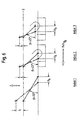
- FIG. 6 shows a schematic, greatly simplified schematic diagram of an essential partial area of a spreading device of a device according to the invention in accordance with a fourth embodiment.
- This variant is similar in its basic construction to the embodiment according to FIG. 4 and illustrates a case in which the dimensions of the device components used, ie here the lengths of the levers (lever 1, lever 2 and lever 3) and for example the arrangement and dimension of the pressure pieces and thus the position of the lever articulation points in relation to a starting position are different for each spreading area.
- the upper end points of all three levers lie at a common vertical height, which is indicated in FIG. 6 by a line "0".
- This example shows well that with a certain construction the length of the lever does not necessarily have to influence the angle ⁇ .
- Lever 3 is shorter than lever 2, but has the same angle ⁇ (here: 45 °).
- ⁇ 45 °
- different expansion strokes h can be achieved in the axial direction, as indicated in the drawing.
- a desired start of spreading and breaking in time or a different build-up of force with the same stroke H A can then be achieved by appropriate design of the lever length and corresponding angle ⁇ .
- the upper ends of the levers or the associated upper lever pivot points can, for example, be at a common height in an initial position (here: line "0"), while the respective lower lever ends or the associated lower lever pivot points can lie at different positions (compare levers 2 and lever 3).
- a corresponding configuration could, for example, also be used analogously for example 7 described above.
- the invention is not limited to the above embodiments, which is only the general explanation of the core idea serve the invention, limited. Within the scope of protection the device according to the invention can rather also others as the configurations described above.
- the wedge elements 18, 20 of the Spreading control device of FIG. 2 can also be used larger units can be summarized. Furthermore, it is possible the wedge elements 18 on both sides of the elongated actuator 16 and the wedge elements 20 to provide on both mandrel halves 12, 14. In the event of The use of crushing segments can also result in wedge surfaces be arranged on the inside of the crushing segments.
- the lever arms 42, 54, 56th basically also directly, for example via a Articulated connection with the actuating element 40 or the Crushing segment 38 may be connected.
Landscapes
- Engineering & Computer Science (AREA)
- Mechanical Engineering (AREA)
- Perforating, Stamping-Out Or Severing By Means Other Than Cutting (AREA)
- Mutual Connection Of Rods And Tubes (AREA)
- Electrical Discharge Machining, Electrochemical Machining, And Combined Machining (AREA)
- External Artificial Organs (AREA)
- Combined Means For Separation Of Solids (AREA)
- Press Drives And Press Lines (AREA)
- Shafts, Cranks, Connecting Bars, And Related Bearings (AREA)
- Manufacture Of Motors, Generators (AREA)
- Processing Of Stones Or Stones Resemblance Materials (AREA)
Claims (17)
- Dispositif pour la division par rupture d'une pièce (2) comportant plusieurs tronçons (4) placés en anneau l'un derrière l'autre en alignement axial, avec au moins un dispositif d'écartement (10, 30) pouvant être introduit axialement (A) dans un alésage (6) formé par un tronçon annulaire (4) de la pièce et présentant au moins un élément écarteur (14, 38) pouvant être écarté sur au moins deux zones d'écartement séparées l'une de l'autre suivant la direction axiale (A),
caractérisé en ce que
le dispositif d'écartement (10, 30) est doté d'un dispositif de contrôle de l'écartement intégré (16, 18, 20, 22 ; 40, 42, 44, 46, 48, 50, 52 ; α ; β ; β1 ; β2) interagissant avec au moins un élément écarteur (14, 38) et en ce que ce dispositif de contrôle de l'écartement intégré est choisi dans un groupe de dispositifs de contrôle de l'écartement englobant :un dispositif de contrôle de l'écartement intégré destiné au contrôle d'une position variable des deux zones d'écartement au moins,un dispositif de contrôle de l'écartement intégré destiné au contrôle d'une amplitude d'écartement variable des deux zones d'écartement au moins,un dispositif de contrôle de l'écartement intégré destiné au contrôle d'un instant d'écartement variable des deux zones d'écartement au moins,un dispositif de contrôle de l'écartement intégré destiné au contrôle d'un ordre d'écartement variable des deux zones d'écartement au moins,un dispositif de contrôle de l'écartement intégré représentant une combinaison de deux ou plus des dispositifs de contrôle de l'écartement intégrés indiqués ci-dessus. - Dispositif selon revendication 1,
caractérisé en ce que
le dispositif d'écartement possède au moins mandrin d'écartement (10, 30) comportant deux moitiés (12, 14 ; 32, 34) dont au moins une dispose des zones d'écartement (38) distantes l'une de l'autre dans le sens axial (A) et en ce que le dispositif de contrôle de l'écartement (16, 18, 20, 22 ; 40, 42, 44, 46, 48, 50, 52 ; α ; β ; β1 ; β2) est placé entre les moitiés du mandrin d'écartement (12, 14 ; 32, 34). - Dispositif selon revendication 2,
caractérisé en ce que
le dispositif de contrôle de l'écartement comporte :au moins un organe de manoeuvre (16) allongé passant entre les deux moitiés du mandrin d'écartement (12, 14), et possédant une pluralité d'éléments de calage (18) ayant des premières surfaces de calage (18.2) formant un angle (α) par rapport à la direction axiale (A) etune pluralité de deuxièmes éléments de calage (20) fixés sur au moins une (14) des deux moitiés du mandrin d'écartement (12, 14), ayant des deuxièmes surfaces de calage (20.2) formant un angle (α) par rapport à la direction axiale (A),les deuxièmes éléments de calage (20) étant associés par complémentarité aux premiers éléments de calage (18) et entraínant l'écartement d'une zone d'écartement respective lorsqu'on actionne l'organe de manoeuvre (16) en interaction avec un premier élément de calage (18) associé etla distance axiale opposée (DA1, DA2 ... DAX) des premiers éléments de calage (18) et/ou la distance axiale opposée (DB1, DB2 ... DBX) des deuxièmes éléments de calage (20) pouvant être réglée de façon variable (22). - Dispositif selon revendication 3,
caractérisé en ce que
la distance axiale opposée (DA1, DA2 ... DAX) entre des premiers éléments de calage voisins successifs (18)
et/ou
la distance axiale opposée (DB1, DB2 ... DBX) entre des deuxièmes éléments de calage voisins successifs (20) s'agrandit. - Dispositif selon revendication 3 ou 4,
caractérisé en ce que
les éléments de calage (18, 20) sont échangeables (20). - Dispositif selon revendication 3, 4 ou 5,
caractérisé en ce que
au moins une (14) des moitiés du mandrin d'écartement (12, 14) est divisée en tronçons (14A, 14B, 14C), reliés (58) entre eux de façon mobile, chacun de ces tronçons (14A, 14B, 14C) étant associé à une zone d'écartement correspondante de sorte que les zones d'écartement respectives puissent être écartées indépendamment l'une de l'autre. - Dispositif selon revendication 6,
caractérisé en ce que
la liaison mobile des tronçons des moitiés du mandrin d'écartement (14A, 14B, 14C) est une liaison par accouplement et/ou une liaison flexible (58) et/ou une liaison mono-articulée et/ou multi-articulée. - Dispositif selon revendication 2
caractérisé en ce quele dispositif de contrôle de l'écartement comprend une pluralité d'éléments de levier (42 ; 54, 56), distants l'un de l'autre suivant la direction axiale (A), qui sont placés entre les deux moitiés du mandrin d'écartement (32, 34), forment un angle obtus (β ; β1, β2) transversalement à la direction axiale (A) et interagissent avec au moins un élément d'écartement (38),au moins un organe de manoeuvre (40), s'étendant entre les deux moitiés de mandrin d'écartement (32, 34) suivant la direction axiale (A), qui est relié directement et/ou indirectement (44) avec une première extrémité (42.2) d'un élément de levier (42) et qui interagit avec celle-ci, etau moins un contrefort d'élément de levier (50) placé dans une zone d'écartement (38) et en liaison active directe et/ou indirecte avec celle-ci, qui est relié directement et/ou indirectement avec une deuxième extrémité (42.4) d'un élément de levier (42) et qui soutient la deuxième extrémité (42.4). - Dispositif selon revendication 8,
caractérisé en ce que
la deuxième extrémité (42.4) d'un élément de levier (42) est logée dans un membre de pression (50) mobile de façon sensiblement perpendiculaire par rapport à la direction axiale (A), qui interagit avec l'élément d'écartement (38). - Dispositif selon l'une quelconque des revendications 8 ou 9,
caractérisé en ce que
au moins un élément de levier (42 ; 54, 56) est associé à chaque zone d'écartement (38). - Dispositif selon revendication 10,
caractérisé en ce que
deux éléments de levier (54, 56) sont associés à chaque zone d'écartement (38) et sont placés symétriquement l'un par rapport à l'autre par rapport à la direction axiale (A) du dispositif d'écartement (30) et forment une paire d'éléments de levier (54, 56), l'organe de manoeuvre (40) passant entre la paire d'éléments de levier (54, 56) et les extrémités (54.2, 56.2) de la paire d'éléments de levier (54, 56), tournées vers l'organe de manoeuvre étant reliées directement et/ou indirectement (44) avec l'organe de manoeuvre (40) et interagissant avec celui-ci. - Dispositif selon revendication 11,
caractérisé en ce que
les extrémités (54.2, 56.2) de la paire d'éléments de levier (54, 56), opposées à l'organe de manoeuvre, sont logées chacune dans un membre de pression (50) dont au moins un est mobile de façon sensiblement perpendiculaire à la direction axiale (A) et interagit avec l'élément d'écartement (38). - Dispositif selon l'une quelconque des revendications 8 à 12,
caractérisé en ce que
les éléments de levier (42 ; 54, 56) forment un angle obtus (β) par rapport à la direction axiale. - Dispositif selon revendication 13
caractérisé en ce que
la position angulaire (β, β1, β2) d'un élément de levier (42 ; 54, 56) peut être réglée individuellement. - Dispositif selon l'une quelconque des revendications 8 à 14,
caractérisé en ce que
les éléments de levier (42 ; 54, 56) sont de même longueur (L). - Dispositif selon l'une quelconque des revendications 8 à 15,
caractérisé en ce que
les éléments de levier (42 ; 54, 56) sont de longueur (L) différente. - Dispositif selon l'une ou plusieurs des revendications précédentes,
caractérisé en ce que
le dispositif d'écartement (10) est équipé, sur un tronçon antérieur par rapport à la direction d'introduction axiale (A), d'au moins un dispositif de séparation (26, 28) destiné à réaliser une ou plusieurs encoches de rupture (8) dans l'alésage (6, 6.2) pendant et/ou après l'introduction du dispositif d'écartement (10).
Applications Claiming Priority (3)
| Application Number | Priority Date | Filing Date | Title |
|---|---|---|---|
| DE19918067 | 1999-04-21 | ||
| DE19918067A DE19918067A1 (de) | 1999-04-21 | 1999-04-21 | Vorrichtung zum Bruchtrennen eines Werkstücks |
| PCT/EP2000/003579 WO2000062965A1 (fr) | 1999-04-21 | 2000-04-19 | Dispositif pour la division par rupture d'une piece |
Publications (2)
| Publication Number | Publication Date |
|---|---|
| EP1171260A1 EP1171260A1 (fr) | 2002-01-16 |
| EP1171260B1 true EP1171260B1 (fr) | 2003-02-26 |
Family
ID=7905344
Family Applications (1)
| Application Number | Title | Priority Date | Filing Date |
|---|---|---|---|
| EP00929394A Expired - Lifetime EP1171260B1 (fr) | 1999-04-21 | 2000-04-19 | Dispositif pour la division par rupture d'une piece |
Country Status (10)
| Country | Link |
|---|---|
| US (1) | US6641016B2 (fr) |
| EP (1) | EP1171260B1 (fr) |
| JP (1) | JP4467192B2 (fr) |
| CN (1) | CN1190289C (fr) |
| AT (1) | ATE233146T1 (fr) |
| BR (1) | BR0009876A (fr) |
| DE (2) | DE19918067A1 (fr) |
| ES (1) | ES2190968T3 (fr) |
| PT (1) | PT1171260E (fr) |
| WO (1) | WO2000062965A1 (fr) |
Families Citing this family (12)
| Publication number | Priority date | Publication date | Assignee | Title |
|---|---|---|---|---|
| DE19918063A1 (de) * | 1999-04-21 | 2000-10-26 | Kessler Kg Maschf | Verfahren und Vorrichtung zum Bruchtrennen eines Werkstücks |
| DE10320372A1 (de) * | 2003-05-07 | 2004-12-16 | Alfing Kessler Sondermaschinen Gmbh | Verfahren und Vorrichtung zum Bruchtrennen von Lagerdeckeln |
| JP2005036902A (ja) * | 2003-07-16 | 2005-02-10 | Honda Motor Co Ltd | コネクティングロッドの分割加工方法及びその分割加工装置 |
| JP2005074537A (ja) * | 2003-08-28 | 2005-03-24 | Honda Motor Co Ltd | コネクティングロッドの分割加工方法及びその分割加工装置 |
| CN100343012C (zh) * | 2004-04-26 | 2007-10-17 | 吉林大学 | 发动机曲轴箱体轴承座裂解加工方法及装置 |
| ES2302165T3 (es) * | 2005-02-09 | 2008-07-01 | Vigel S.P.A. | Aparato para separar la tapa de cojinete de una biela mediante fractura. |
| US20120066888A1 (en) * | 2009-03-16 | 2012-03-22 | Alfing Kessler Sondermaschinen Gmbh | Method for joining two components of a unit |
| WO2011111783A1 (fr) * | 2010-03-12 | 2011-09-15 | カルピス株式会社 | Agent de régulation de l'augmentation et de la diminution de lactobacillus bifidus dans le côlon |
| WO2012101748A1 (fr) * | 2011-01-24 | 2012-08-02 | トヨタ自動車 株式会社 | Procédé pour la rupture de bielle |
| CA2847821C (fr) | 2011-09-06 | 2018-12-11 | Gaindu, S.L. | Machine pour la fracture d'une bielle |
| CN108000122B (zh) * | 2017-12-08 | 2019-03-22 | 吉林大学 | 曲轴箱体轴承座裂解加工装置 |
| CN108058003B (zh) * | 2017-12-13 | 2019-06-25 | 吉林大学 | 一种减速器壳体轴承座胀断设备及其胀断方法 |
Family Cites Families (10)
| Publication number | Priority date | Publication date | Assignee | Title |
|---|---|---|---|---|
| US4569109A (en) * | 1984-07-02 | 1986-02-11 | General Motors Corporation | Method of making a split bearing assembly |
| US4684267A (en) * | 1984-07-02 | 1987-08-04 | General Motors Corporation | Split bearing assemblies |
| US5131577A (en) * | 1988-05-17 | 1992-07-21 | Ford Motor Company | Apparatus for making a powder metal connecting rod |
| ATE98343T1 (de) * | 1989-05-10 | 1993-12-15 | Kessler Kg Maschf | Verfahren und vorrichtung zum bruchtrennen von pleueln. |
| US5274919A (en) * | 1992-05-08 | 1994-01-04 | Giddings & Lewis, Inc. | Method of cracking a connecting rod |
| US5503317A (en) * | 1994-03-31 | 1996-04-02 | Tri-Way Machine Ltd. | Apparatus for fracturing connecting rods preforms |
| DE4413255A1 (de) * | 1994-04-16 | 1995-10-19 | Bayerische Motoren Werke Ag | Verfahren zum Bruchtrennen des Lagerdeckels einer mehrteiligen Lageranordnung, insbesondere in Kurbelgehäusen von Brennkraftmaschinen |
| IT1268130B1 (it) * | 1994-10-18 | 1997-02-20 | Vigel Spa | Procedimento e macchina per la separazione mediante rottura del cappello di testa delle bielle, particolarmente bielle per motori |
| DE19547388A1 (de) * | 1995-12-19 | 1997-06-26 | Bayerische Motoren Werke Ag | Herstellverfahren für ein Guß-Maschinenteil mit einer durch Bruchtrennen mehrteilig gestalteten Lageranordnung |
| DE19704131C2 (de) * | 1997-02-04 | 2003-01-02 | Ex Cell O Gmbh | Verfahren und Vorrichtung zum Bruchtrennen |
-
1999
- 1999-04-21 DE DE19918067A patent/DE19918067A1/de not_active Ceased
-
2000
- 2000-04-19 AT AT00929394T patent/ATE233146T1/de active
- 2000-04-19 JP JP2000612090A patent/JP4467192B2/ja not_active Expired - Lifetime
- 2000-04-19 DE DE50001327T patent/DE50001327D1/de not_active Expired - Lifetime
- 2000-04-19 EP EP00929394A patent/EP1171260B1/fr not_active Expired - Lifetime
- 2000-04-19 CN CNB008064377A patent/CN1190289C/zh not_active Expired - Fee Related
- 2000-04-19 WO PCT/EP2000/003579 patent/WO2000062965A1/fr not_active Ceased
- 2000-04-19 BR BR0009876-0A patent/BR0009876A/pt not_active Application Discontinuation
- 2000-04-19 PT PT00929394T patent/PT1171260E/pt unknown
- 2000-04-19 ES ES00929394T patent/ES2190968T3/es not_active Expired - Lifetime
-
2001
- 2001-09-27 US US09/965,318 patent/US6641016B2/en not_active Expired - Fee Related
Also Published As
| Publication number | Publication date |
|---|---|
| WO2000062965A1 (fr) | 2000-10-26 |
| PT1171260E (pt) | 2003-06-30 |
| DE19918067A1 (de) | 2000-10-26 |
| ES2190968T3 (es) | 2003-09-01 |
| BR0009876A (pt) | 2002-01-22 |
| US6641016B2 (en) | 2003-11-04 |
| ATE233146T1 (de) | 2003-03-15 |
| CN1190289C (zh) | 2005-02-23 |
| DE50001327D1 (de) | 2003-04-03 |
| CN1347356A (zh) | 2002-05-01 |
| JP4467192B2 (ja) | 2010-05-26 |
| EP1171260A1 (fr) | 2002-01-16 |
| US20020070257A1 (en) | 2002-06-13 |
| JP2002542051A (ja) | 2002-12-10 |
Similar Documents
| Publication | Publication Date | Title |
|---|---|---|
| DE3323254C2 (de) | Blindbolzen mit Sperrkragen | |
| EP1171260B1 (fr) | Dispositif pour la division par rupture d'une piece | |
| EP0417674B1 (fr) | Outil évaseur pour pièces à usiner creuses | |
| EP3012924A1 (fr) | Pince de pression | |
| DE102010014322A1 (de) | Werkzeugkopf für ein rotierendes Werkzeug | |
| DE60007980T2 (de) | Holmverriegelung durch reibung | |
| EP2995401B1 (fr) | Dispositif de serrage | |
| DE102005028366B4 (de) | Bohrstange zur Bearbeitung hintereinander liegender Stege | |
| WO1990000098A1 (fr) | Presse radiale pour pieces sensiblement cylindriques | |
| DE102011100965A1 (de) | Pressbacke und Verfahren zum Herstellen einer Pressverbindung | |
| EP1304094B1 (fr) | Appariel de fabrication d'un tampon | |
| EP3595829B1 (fr) | Dispositif pour injecter un noyau | |
| DE212011100163U1 (de) | Vorrichtung zum Bruchtrennen einer Pleuelstange | |
| DE60107747T2 (de) | Schalter mit Lichtbogenbeblasung, versehen mit einer Lichtbogenkammer mit reduzierter Gaskompression und hin- und hergehendem Kolben | |
| DE102009032620A1 (de) | Gusswerkzeug und Gussmaschine mit einem solchen Gusswerkzeug | |
| DE19717467A1 (de) | Spannstock | |
| DE102004045600A1 (de) | Puffersystem | |
| EP1355749A1 (fr) | Procede de montage d'un element de fonction sur une piece de metal deformable a l'aide d'un procede de formage sous haute pression, piece assemblee et matrice | |
| LU85612A1 (fr) | Greifvorrichtung fuer in das stichloch von metallurgischen ofen eintreibbare und aus diesem herausziehbare stangen,insbesondere abstichstangen | |
| DE202020102064U1 (de) | Spannbare elektrische Heizvorrichtung | |
| DE102009014567A1 (de) | Gusswerkzeug | |
| DE3930710C2 (fr) | ||
| EP0653258B1 (fr) | Machine à forger | |
| EP3273070A1 (fr) | Dispositif de retenue d'un corps en forme de tige avec support de couple et module rétroactif correspondant | |
| DE102005012297B4 (de) | Schmiedemaschine |
Legal Events
| Date | Code | Title | Description |
|---|---|---|---|
| PUAI | Public reference made under article 153(3) epc to a published international application that has entered the european phase |
Free format text: ORIGINAL CODE: 0009012 |
|
| 17P | Request for examination filed |
Effective date: 20010920 |
|
| AK | Designated contracting states |
Kind code of ref document: A1 Designated state(s): AT BE CH CY DE DK ES FI FR GB GR IE IT LI LU MC NL PT SE |
|
| AX | Request for extension of the european patent |
Free format text: AL;LT;LV;MK;RO;SI |
|
| GRAG | Despatch of communication of intention to grant |
Free format text: ORIGINAL CODE: EPIDOS AGRA |
|
| 17Q | First examination report despatched |
Effective date: 20020415 |
|
| GRAG | Despatch of communication of intention to grant |
Free format text: ORIGINAL CODE: EPIDOS AGRA |
|
| GRAH | Despatch of communication of intention to grant a patent |
Free format text: ORIGINAL CODE: EPIDOS IGRA |
|
| GRAH | Despatch of communication of intention to grant a patent |
Free format text: ORIGINAL CODE: EPIDOS IGRA |
|
| GRAA | (expected) grant |
Free format text: ORIGINAL CODE: 0009210 |
|
| AK | Designated contracting states |
Designated state(s): AT BE CH CY DE DK ES FI FR GB GR IE IT LI LU MC NL PT SE |
|
| PG25 | Lapsed in a contracting state [announced via postgrant information from national office to epo] |
Ref country code: GR Free format text: LAPSE BECAUSE OF FAILURE TO SUBMIT A TRANSLATION OF THE DESCRIPTION OR TO PAY THE FEE WITHIN THE PRESCRIBED TIME-LIMIT Effective date: 20030226 Ref country code: IE Free format text: LAPSE BECAUSE OF FAILURE TO SUBMIT A TRANSLATION OF THE DESCRIPTION OR TO PAY THE FEE WITHIN THE PRESCRIBED TIME-LIMIT Effective date: 20030226 Ref country code: FI Free format text: LAPSE BECAUSE OF FAILURE TO SUBMIT A TRANSLATION OF THE DESCRIPTION OR TO PAY THE FEE WITHIN THE PRESCRIBED TIME-LIMIT Effective date: 20030226 |
|
| REG | Reference to a national code |
Ref country code: GB Ref legal event code: FG4D Free format text: NOT ENGLISH |
|
| REG | Reference to a national code |
Ref country code: CH Ref legal event code: EP |
|
| GBT | Gb: translation of ep patent filed (gb section 77(6)(a)/1977) |
Effective date: 20030226 |
|
| REG | Reference to a national code |
Ref country code: IE Ref legal event code: FG4D Free format text: GERMAN |
|
| REF | Corresponds to: |
Ref document number: 50001327 Country of ref document: DE Date of ref document: 20030403 Kind code of ref document: P |
|
| PG25 | Lapsed in a contracting state [announced via postgrant information from national office to epo] |
Ref country code: CY Free format text: LAPSE BECAUSE OF FAILURE TO SUBMIT A TRANSLATION OF THE DESCRIPTION OR TO PAY THE FEE WITHIN THE PRESCRIBED TIME-LIMIT Effective date: 20030419 Ref country code: LU Free format text: LAPSE BECAUSE OF NON-PAYMENT OF DUE FEES Effective date: 20030419 |
|
| REG | Reference to a national code |
Ref country code: SE Ref legal event code: TRGR |
|
| PG25 | Lapsed in a contracting state [announced via postgrant information from national office to epo] |
Ref country code: MC Free format text: LAPSE BECAUSE OF NON-PAYMENT OF DUE FEES Effective date: 20030430 |
|
| PG25 | Lapsed in a contracting state [announced via postgrant information from national office to epo] |
Ref country code: DK Free format text: LAPSE BECAUSE OF FAILURE TO SUBMIT A TRANSLATION OF THE DESCRIPTION OR TO PAY THE FEE WITHIN THE PRESCRIBED TIME-LIMIT Effective date: 20030526 |
|
| REG | Reference to a national code |
Ref country code: PT Ref legal event code: SC4A Free format text: AVAILABILITY OF NATIONAL TRANSLATION Effective date: 20030509 |
|
| ET | Fr: translation filed | ||
| LTIE | Lt: invalidation of european patent or patent extension |
Effective date: 20030226 |
|
| REG | Reference to a national code |
Ref country code: ES Ref legal event code: FG2A Ref document number: 2190968 Country of ref document: ES Kind code of ref document: T3 |
|
| REG | Reference to a national code |
Ref country code: IE Ref legal event code: FD4D Ref document number: 1171260E Country of ref document: IE |
|
| PLBE | No opposition filed within time limit |
Free format text: ORIGINAL CODE: 0009261 |
|
| STAA | Information on the status of an ep patent application or granted ep patent |
Free format text: STATUS: NO OPPOSITION FILED WITHIN TIME LIMIT |
|
| 26N | No opposition filed |
Effective date: 20031127 |
|
| PGFP | Annual fee paid to national office [announced via postgrant information from national office to epo] |
Ref country code: PT Payment date: 20040227 Year of fee payment: 5 |
|
| PGFP | Annual fee paid to national office [announced via postgrant information from national office to epo] |
Ref country code: BE Payment date: 20040303 Year of fee payment: 5 |
|
| PGFP | Annual fee paid to national office [announced via postgrant information from national office to epo] |
Ref country code: GB Payment date: 20040408 Year of fee payment: 5 |
|
| PG25 | Lapsed in a contracting state [announced via postgrant information from national office to epo] |
Ref country code: CH Free format text: LAPSE BECAUSE OF NON-PAYMENT OF DUE FEES Effective date: 20040430 Ref country code: LI Free format text: LAPSE BECAUSE OF NON-PAYMENT OF DUE FEES Effective date: 20040430 |
|
| REG | Reference to a national code |
Ref country code: CH Ref legal event code: PL |
|
| PG25 | Lapsed in a contracting state [announced via postgrant information from national office to epo] |
Ref country code: GB Free format text: LAPSE BECAUSE OF NON-PAYMENT OF DUE FEES Effective date: 20050419 |
|
| PG25 | Lapsed in a contracting state [announced via postgrant information from national office to epo] |
Ref country code: BE Free format text: LAPSE BECAUSE OF NON-PAYMENT OF DUE FEES Effective date: 20050430 |
|
| PG25 | Lapsed in a contracting state [announced via postgrant information from national office to epo] |
Ref country code: PT Free format text: LAPSE BECAUSE OF NON-PAYMENT OF DUE FEES Effective date: 20051019 |
|
| BERE | Be: lapsed |
Owner name: *ALFING KESSLER SONDERMASCHINEN G.M.B.H. Effective date: 20050430 |
|
| GBPC | Gb: european patent ceased through non-payment of renewal fee |
Effective date: 20050419 |
|
| BERE | Be: lapsed |
Owner name: *ALFING KESSLER SONDERMASCHINEN G.M.B.H. Effective date: 20050430 |
|
| PGFP | Annual fee paid to national office [announced via postgrant information from national office to epo] |
Ref country code: FR Payment date: 20120419 Year of fee payment: 13 |
|
| PGFP | Annual fee paid to national office [announced via postgrant information from national office to epo] |
Ref country code: ES Payment date: 20120403 Year of fee payment: 13 |
|
| PGFP | Annual fee paid to national office [announced via postgrant information from national office to epo] |
Ref country code: IT Payment date: 20130415 Year of fee payment: 14 |
|
| REG | Reference to a national code |
Ref country code: FR Ref legal event code: ST Effective date: 20131231 |
|
| PG25 | Lapsed in a contracting state [announced via postgrant information from national office to epo] |
Ref country code: FR Free format text: LAPSE BECAUSE OF NON-PAYMENT OF DUE FEES Effective date: 20130430 |
|
| REG | Reference to a national code |
Ref country code: DE Ref legal event code: R082 Ref document number: 50001327 Country of ref document: DE Representative=s name: PATENTANWAELTE BREGENZER UND REULE PARTNERSCHA, DE |
|
| PG25 | Lapsed in a contracting state [announced via postgrant information from national office to epo] |
Ref country code: IT Free format text: LAPSE BECAUSE OF NON-PAYMENT OF DUE FEES Effective date: 20140419 |
|
| REG | Reference to a national code |
Ref country code: ES Ref legal event code: FD2A Effective date: 20150527 |
|
| PG25 | Lapsed in a contracting state [announced via postgrant information from national office to epo] |
Ref country code: ES Free format text: LAPSE BECAUSE OF NON-PAYMENT OF DUE FEES Effective date: 20140420 |
|
| PGFP | Annual fee paid to national office [announced via postgrant information from national office to epo] |
Ref country code: NL Payment date: 20170419 Year of fee payment: 18 |
|
| PGFP | Annual fee paid to national office [announced via postgrant information from national office to epo] |
Ref country code: SE Payment date: 20170419 Year of fee payment: 18 |
|
| PGFP | Annual fee paid to national office [announced via postgrant information from national office to epo] |
Ref country code: DE Payment date: 20180423 Year of fee payment: 19 |
|
| PGFP | Annual fee paid to national office [announced via postgrant information from national office to epo] |
Ref country code: AT Payment date: 20180427 Year of fee payment: 19 |
|
| REG | Reference to a national code |
Ref country code: SE Ref legal event code: EUG |
|
| REG | Reference to a national code |
Ref country code: NL Ref legal event code: MM Effective date: 20180501 |
|
| PG25 | Lapsed in a contracting state [announced via postgrant information from national office to epo] |
Ref country code: NL Free format text: LAPSE BECAUSE OF NON-PAYMENT OF DUE FEES Effective date: 20180501 Ref country code: SE Free format text: LAPSE BECAUSE OF NON-PAYMENT OF DUE FEES Effective date: 20180420 |
|
| REG | Reference to a national code |
Ref country code: DE Ref legal event code: R119 Ref document number: 50001327 Country of ref document: DE |
|
| REG | Reference to a national code |
Ref country code: AT Ref legal event code: MM01 Ref document number: 233146 Country of ref document: AT Kind code of ref document: T Effective date: 20190419 |
|
| PG25 | Lapsed in a contracting state [announced via postgrant information from national office to epo] |
Ref country code: AT Free format text: LAPSE BECAUSE OF NON-PAYMENT OF DUE FEES Effective date: 20190419 Ref country code: DE Free format text: LAPSE BECAUSE OF NON-PAYMENT OF DUE FEES Effective date: 20191101 |