EP1172279A2 - Hydraulische Lenkanlage für Nutzfahrzeuge - Google Patents
Hydraulische Lenkanlage für Nutzfahrzeuge Download PDFInfo
- Publication number
- EP1172279A2 EP1172279A2 EP01115597A EP01115597A EP1172279A2 EP 1172279 A2 EP1172279 A2 EP 1172279A2 EP 01115597 A EP01115597 A EP 01115597A EP 01115597 A EP01115597 A EP 01115597A EP 1172279 A2 EP1172279 A2 EP 1172279A2
- Authority
- EP
- European Patent Office
- Prior art keywords
- steering system
- valve
- check valve
- hydraulic cylinder
- check
- Prior art date
- Legal status (The legal status is an assumption and is not a legal conclusion. Google has not performed a legal analysis and makes no representation as to the accuracy of the status listed.)
- Granted
Links
Images

Classifications
-
- F—MECHANICAL ENGINEERING; LIGHTING; HEATING; WEAPONS; BLASTING
- F15—FLUID-PRESSURE ACTUATORS; HYDRAULICS OR PNEUMATICS IN GENERAL
- F15B—SYSTEMS ACTING BY MEANS OF FLUIDS IN GENERAL; FLUID-PRESSURE ACTUATORS, e.g. SERVOMOTORS; DETAILS OF FLUID-PRESSURE SYSTEMS, NOT OTHERWISE PROVIDED FOR
- F15B11/00—Servomotor systems without provision for follow-up action; Circuits therefor
- F15B11/02—Systems essentially incorporating special features for controlling the speed or actuating force of an output member
- F15B11/028—Systems essentially incorporating special features for controlling the speed or actuating force of an output member for controlling the actuating force
-
- B—PERFORMING OPERATIONS; TRANSPORTING
- B62—LAND VEHICLES FOR TRAVELLING OTHERWISE THAN ON RAILS
- B62D—MOTOR VEHICLES; TRAILERS
- B62D5/00—Power-assisted or power-driven steering
- B62D5/06—Power-assisted or power-driven steering fluid, i.e. using a pressurised fluid for most or all the force required for steering a vehicle
- B62D5/062—Details, component parts
-
- F—MECHANICAL ENGINEERING; LIGHTING; HEATING; WEAPONS; BLASTING
- F15—FLUID-PRESSURE ACTUATORS; HYDRAULICS OR PNEUMATICS IN GENERAL
- F15B—SYSTEMS ACTING BY MEANS OF FLUIDS IN GENERAL; FLUID-PRESSURE ACTUATORS, e.g. SERVOMOTORS; DETAILS OF FLUID-PRESSURE SYSTEMS, NOT OTHERWISE PROVIDED FOR
- F15B11/00—Servomotor systems without provision for follow-up action; Circuits therefor
- F15B11/02—Systems essentially incorporating special features for controlling the speed or actuating force of an output member
- F15B11/04—Systems essentially incorporating special features for controlling the speed or actuating force of an output member for controlling the speed
- F15B11/0413—Systems essentially incorporating special features for controlling the speed or actuating force of an output member for controlling the speed in one direction only, with no control in the reverse direction, e.g. check valve in parallel with a throttle valve
-
- F—MECHANICAL ENGINEERING; LIGHTING; HEATING; WEAPONS; BLASTING
- F16—ENGINEERING ELEMENTS AND UNITS; GENERAL MEASURES FOR PRODUCING AND MAINTAINING EFFECTIVE FUNCTIONING OF MACHINES OR INSTALLATIONS; THERMAL INSULATION IN GENERAL
- F16F—SPRINGS; SHOCK-ABSORBERS; MEANS FOR DAMPING VIBRATION
- F16F9/00—Springs, vibration-dampers, shock-absorbers, or similarly-constructed movement-dampers using a fluid or the equivalent as damping medium
- F16F9/32—Details
- F16F9/50—Special means providing automatic damping adjustment, i.e. self-adjustment of damping by particular sliding movements of a valve element, other than flexions or displacement of valve discs; Special means providing self-adjustment of spring characteristics
-
- F—MECHANICAL ENGINEERING; LIGHTING; HEATING; WEAPONS; BLASTING
- F16—ENGINEERING ELEMENTS AND UNITS; GENERAL MEASURES FOR PRODUCING AND MAINTAINING EFFECTIVE FUNCTIONING OF MACHINES OR INSTALLATIONS; THERMAL INSULATION IN GENERAL
- F16K—VALVES; TAPS; COCKS; ACTUATING-FLOATS; DEVICES FOR VENTING OR AERATING
- F16K47/00—Means in valves for absorbing fluid energy
- F16K47/08—Means in valves for absorbing fluid energy for decreasing pressure or noise level and having a throttling member separate from the closure member, e.g. screens, slots, labyrinths
- F16K47/10—Means in valves for absorbing fluid energy for decreasing pressure or noise level and having a throttling member separate from the closure member, e.g. screens, slots, labyrinths in which the medium in one direction must flow through the throttling channel, and in the other direction may flow through a much wider channel parallel to the throttling channel
-
- F—MECHANICAL ENGINEERING; LIGHTING; HEATING; WEAPONS; BLASTING
- F15—FLUID-PRESSURE ACTUATORS; HYDRAULICS OR PNEUMATICS IN GENERAL
- F15B—SYSTEMS ACTING BY MEANS OF FLUIDS IN GENERAL; FLUID-PRESSURE ACTUATORS, e.g. SERVOMOTORS; DETAILS OF FLUID-PRESSURE SYSTEMS, NOT OTHERWISE PROVIDED FOR
- F15B2211/00—Circuits for servomotor systems
- F15B2211/20—Fluid pressure source, e.g. accumulator or variable axial piston pump
- F15B2211/205—Systems with pumps
- F15B2211/2053—Type of pump
-
- F—MECHANICAL ENGINEERING; LIGHTING; HEATING; WEAPONS; BLASTING
- F15—FLUID-PRESSURE ACTUATORS; HYDRAULICS OR PNEUMATICS IN GENERAL
- F15B—SYSTEMS ACTING BY MEANS OF FLUIDS IN GENERAL; FLUID-PRESSURE ACTUATORS, e.g. SERVOMOTORS; DETAILS OF FLUID-PRESSURE SYSTEMS, NOT OTHERWISE PROVIDED FOR
- F15B2211/00—Circuits for servomotor systems
- F15B2211/30—Directional control
- F15B2211/305—Directional control characterised by the type of valves
- F15B2211/30525—Directional control valves, e.g. 4/3-directional control valve
-
- F—MECHANICAL ENGINEERING; LIGHTING; HEATING; WEAPONS; BLASTING
- F15—FLUID-PRESSURE ACTUATORS; HYDRAULICS OR PNEUMATICS IN GENERAL
- F15B—SYSTEMS ACTING BY MEANS OF FLUIDS IN GENERAL; FLUID-PRESSURE ACTUATORS, e.g. SERVOMOTORS; DETAILS OF FLUID-PRESSURE SYSTEMS, NOT OTHERWISE PROVIDED FOR
- F15B2211/00—Circuits for servomotor systems
- F15B2211/30—Directional control
- F15B2211/32—Directional control characterised by the type of actuation
- F15B2211/321—Directional control characterised by the type of actuation mechanically
- F15B2211/324—Directional control characterised by the type of actuation mechanically manually, e.g. by using a lever or pedal
-
- F—MECHANICAL ENGINEERING; LIGHTING; HEATING; WEAPONS; BLASTING
- F15—FLUID-PRESSURE ACTUATORS; HYDRAULICS OR PNEUMATICS IN GENERAL
- F15B—SYSTEMS ACTING BY MEANS OF FLUIDS IN GENERAL; FLUID-PRESSURE ACTUATORS, e.g. SERVOMOTORS; DETAILS OF FLUID-PRESSURE SYSTEMS, NOT OTHERWISE PROVIDED FOR
- F15B2211/00—Circuits for servomotor systems
- F15B2211/40—Flow control
- F15B2211/405—Flow control characterised by the type of flow control means or valve
- F15B2211/40507—Flow control characterised by the type of flow control means or valve with constant throttles or orifices
-
- F—MECHANICAL ENGINEERING; LIGHTING; HEATING; WEAPONS; BLASTING
- F15—FLUID-PRESSURE ACTUATORS; HYDRAULICS OR PNEUMATICS IN GENERAL
- F15B—SYSTEMS ACTING BY MEANS OF FLUIDS IN GENERAL; FLUID-PRESSURE ACTUATORS, e.g. SERVOMOTORS; DETAILS OF FLUID-PRESSURE SYSTEMS, NOT OTHERWISE PROVIDED FOR
- F15B2211/00—Circuits for servomotor systems
- F15B2211/40—Flow control
- F15B2211/405—Flow control characterised by the type of flow control means or valve
- F15B2211/40576—Assemblies of multiple valves
- F15B2211/40584—Assemblies of multiple valves the flow control means arranged in parallel with a check valve
-
- F—MECHANICAL ENGINEERING; LIGHTING; HEATING; WEAPONS; BLASTING
- F15—FLUID-PRESSURE ACTUATORS; HYDRAULICS OR PNEUMATICS IN GENERAL
- F15B—SYSTEMS ACTING BY MEANS OF FLUIDS IN GENERAL; FLUID-PRESSURE ACTUATORS, e.g. SERVOMOTORS; DETAILS OF FLUID-PRESSURE SYSTEMS, NOT OTHERWISE PROVIDED FOR
- F15B2211/00—Circuits for servomotor systems
- F15B2211/40—Flow control
- F15B2211/46—Control of flow in the return line, i.e. meter-out control
-
- F—MECHANICAL ENGINEERING; LIGHTING; HEATING; WEAPONS; BLASTING
- F15—FLUID-PRESSURE ACTUATORS; HYDRAULICS OR PNEUMATICS IN GENERAL
- F15B—SYSTEMS ACTING BY MEANS OF FLUIDS IN GENERAL; FLUID-PRESSURE ACTUATORS, e.g. SERVOMOTORS; DETAILS OF FLUID-PRESSURE SYSTEMS, NOT OTHERWISE PROVIDED FOR
- F15B2211/00—Circuits for servomotor systems
- F15B2211/50—Pressure control
- F15B2211/505—Pressure control characterised by the type of pressure control means
- F15B2211/50509—Pressure control characterised by the type of pressure control means the pressure control means controlling a pressure upstream of the pressure control means
- F15B2211/50518—Pressure control characterised by the type of pressure control means the pressure control means controlling a pressure upstream of the pressure control means using pressure relief valves
-
- F—MECHANICAL ENGINEERING; LIGHTING; HEATING; WEAPONS; BLASTING
- F15—FLUID-PRESSURE ACTUATORS; HYDRAULICS OR PNEUMATICS IN GENERAL
- F15B—SYSTEMS ACTING BY MEANS OF FLUIDS IN GENERAL; FLUID-PRESSURE ACTUATORS, e.g. SERVOMOTORS; DETAILS OF FLUID-PRESSURE SYSTEMS, NOT OTHERWISE PROVIDED FOR
- F15B2211/00—Circuits for servomotor systems
- F15B2211/70—Output members, e.g. hydraulic motors or cylinders or control therefor
- F15B2211/705—Output members, e.g. hydraulic motors or cylinders or control therefor characterised by the type of output members or actuators
- F15B2211/7051—Linear output members
- F15B2211/7053—Double-acting output members
-
- F—MECHANICAL ENGINEERING; LIGHTING; HEATING; WEAPONS; BLASTING
- F15—FLUID-PRESSURE ACTUATORS; HYDRAULICS OR PNEUMATICS IN GENERAL
- F15B—SYSTEMS ACTING BY MEANS OF FLUIDS IN GENERAL; FLUID-PRESSURE ACTUATORS, e.g. SERVOMOTORS; DETAILS OF FLUID-PRESSURE SYSTEMS, NOT OTHERWISE PROVIDED FOR
- F15B2211/00—Circuits for servomotor systems
- F15B2211/80—Other types of control related to particular problems or conditions
- F15B2211/86—Control during or prevention of abnormal conditions
- F15B2211/8613—Control during or prevention of abnormal conditions the abnormal condition being oscillations
Definitions
- the invention relates to a hydraulic steering system for commercial vehicles, especially power steering systems and / or auxiliary steering system for trailing and / or leading axles.
- auxiliary steering systems for commercial vehicles are known from practice, those to support maneuverability and used to improve driving dynamics become. These auxiliary steering systems are especially for the rear axle, the trailing axle or the leading axle used so that they also give in can.
- This increases the maneuverability of the corresponding commercial vehicle, for example one Truck with one front axle and two rear axles. It can be provided, for example, that the second rear axle, the so-called trailing axle, is steered up to a certain speed.
- the trailing axle can be controlled electronically, i.e. without mechanical fasteners.
- the energy required for this can be obtained from a hydraulic pump be applied with a hydraulic cylinder connected to the steering angle of the Wheels accordingly.
- the steering angle that turns on the trailing axle can be set by a electronic control unit (ECU) can be specified.
- the control unit can use a control valve accordingly turn.
- a failure of the active system that leads to an adhesion control leads to a deflection of the wheels by forces that exist between the wheel bearing surface and build the tire. Especially when cornering act on the wheels side forces that result in that the steering angle of the wheels changes. This can result in undesirable, rapid vehicle reactions occur that lead to the vehicle breaking away can.
- Power steering generate the assistants for steering.
- Power steering systems are both in terms of their area of application, their job as well as the constructive Structure different from auxiliary steering systems.
- the power steering system known from DE 41 06 310 A1 for motor vehicles has a servo motor, the both work rooms via work lines with one Control valve are connected.
- a damping valve is arranged, the in parallel to each other a check valve, a throttle and has a pressure relief valve. Doing so opens the check valve towards the work area.
- the pressure relief valve opens towards the Control valve.
- the known hydraulic power steering basically concerns the same area of application as the aforementioned Disclosure and those known from practice Damper valve arrangements. There is only one stake for hydraulic power steering on the front axle intended.
- the present invention is based on the object a hydraulic steering system for commercial vehicles, in particular an external power steering system and / or auxiliary steering system to create for trailing and / or leading axles, which is an uncontrolled movement of the steerable axles prevented even if the active system fails and the optimal maneuverability, driving dynamics, Driving stability and tracking stability guaranteed.
- hydraulic steering systems for commercial vehicles in particular power steering systems and / or auxiliary steering systems for trailing and / or leading axles that are electronically controllable for each steering direction a damper valve between the hydraulic cylinder and are provided with a control valve, both Eliminate both light and heavy interference components. Disturbances, e.g. Cross wind or ruts are completely compensated by the damper valves. Due to the electronic control of the steering system is a passing on of the minor interference components to the driver both unnecessary and annoying. The electronically controllable hydraulic steering system can thus work completely independently of the driver and need not be influenced by this.
- the damper valves can be used in a particularly advantageous manner are switched in such a way that large disturbances, especially a complete failure of the active system, is strongly damped, so that the Adjust the driver to the changed driving situation can.
- the damper valves ensure that the The steering angle of the wheels changed only slowly. In order to the driver has enough time to take appropriate measures to seize and respond to the new vehicle response adjust.
- the damper valves can even small wheel movements be damped so that a particularly high Driving safety, driving dynamics and driving stability achieved can be.
- the electronically controllable hydraulic according to the invention Steering system can thus be completely from the front axle steering system be decoupled.
- the solution according to the invention can be used both for preliminary and / or Trailing axles as well as for the rear axle steering or use power steering systems.
- the Damper valves each connected in parallel with a check valve and / or a pressure relief valve and / or have an aperture, it being advantageous if the check valve is designed such that a fluid flow only in the direction of a work space Hydraulic cylinder is possible.
- check valve only allows a fluid flow towards the working area of the hydraulic cylinder enables, it is ensured that even with one complete failure of the active system due to strong damping, no uncontrolled steering movements of the wheels.
- the check valve is provided with a tumbler such that the Check valve closed when not loaded is.
- the tumbler formed such is that the check valve also in through fluid flows towards the working area of the hydraulic cylinder unloaded state against vibrations and weight forces are closed such that a Fluid flow from the working area of the hydraulic cylinder is excluded by the check valve.
- the electronically represented in the embodiment controlled hydraulic rear axle steering system only provides a variant of the electronic controlled hydraulic steering system. Analogously to this can this with external power steering systems and steered Front or trailing axles both on the rear axle as well as on the front axle.
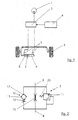
- the hydraulically operated Rear axle steering system a hydraulic pump 1 on the energy for a hydraulic cylinder 2 supplies. It is in the illustrated embodiment just a double-acting hydraulic cylinder 2 provided for the steering angle of the wheels 3 to change in a known manner.
- two hydraulic cylinders 2 can also be provided.
- the target steering angle of the wheels 3, which is at the set the steerable rear axle shown, is specified by an electronic control unit 4. This is done in a known, not shown Way by means of a sensor of the steering angle on the front axle determined and the appropriate information passed on to the control unit 4. Based on the determined Data is controlled by the control unit 4, a control valve 5, the fluid flow to the hydraulic cylinder 2nd controls. Thus, working spaces 6 of the hydraulic cylinder 2 enlarged or reduced accordingly.
- the control valve 5 can be used as a 3-way valve with an open Be trained in the middle.
- the control valve is the control valve as a proportional valve 5 trained.
- the rear axle becomes proportional controlled to the front axle. It can be provided be that the steerable rear axle only up to one certain speed of the commercial vehicle, for example 40 km / h, is steered. At higher driving speeds it can increase driving stability be sensible, the steered wheels 3 in a straight-ahead position bring to.
- damper valves 7 Between the hydraulic cylinder 2 and the control valve 5 are two damper valves 7, the structure of which is shown in FIG. 2 and FIG. 3 is shown in more detail.
- the damper valves 7 it is possible that even small Wheel movements, e.g. due to road bumps, Ruts etc. can be dampened.
- the damper valves 7 are therefore sensitive Reaction that responds even with the smallest amounts of fluid, possible.
- the damper valve 7 shown in Fig. 2 can with a port 8 connected to the hydraulic cylinder 2 become.
- a connection 9 can be connected to a to the control valve 5 leading line or directly on the Control valve 5 can be connected.
- the damper valve 7 has a check valve 10 connected in parallel, a pressure relief valve 11 and an orifice 12.
- the check valve 10 leaves a fluid flow only in the direction of the corresponding work area 6 of the hydraulic cylinder 2 too.
- the pressure in the working space 6 through the pressure relief valve 11 to a certain maximum value limited. An excessive load on the steering parts is thus prevented.
- Through the aperture 12 Return from the work area 6 throttled. Through the Selection of the flow cross section of the orifice 12 can the required damping effect can be set.
- the fluid volume in the hydraulic cylinder 2 or in the work room 6 not completely included so that the steering angle of the Wheels 3 can still change damped
- the check valve 10 provided with a tumbler 13.
- the tumbler as Compression spring 13 formed.
- the check piston 15 is thereby spring-loaded in the closing direction.
- the spring 13 is so arranged that the check valve 10 is closed in the unloaded state.
- Unencumbered State means a state in which no pressure drops at the check valve 10. Thereby, that the check valve 10 by the spring 13th is closed in the unloaded state, one occurs Damping immediately, even with the smallest wheel movements, on. That is, to close the check valve 10 is not a corresponding friction Fluid flow necessary.
- the system is thus preloaded and an optimal disturbance variable compensation is possible.
- Such a closing of the check valve 10 is possible in a simple manner if the pressure spring 13 on the side facing the hydraulic cylinder 2 the check valve 10 is arranged, if so a force in the closing direction on the check piston 15 is exercised.
- This arrangement and the design of the tumbler as spring 13 is a particularly cost-effective, reliable and constructive achieved easy-to-use solution that the check valve 10 closes in the unloaded state.
- the spring 13 can be designed such that the Check valve 10 in the direction of fluid flows Working space 6 of the hydraulic cylinder 2 per se unloaded Condition even with vibrations (preferably in Frequency range from 20 to 50 Hz) of the axis and the Weight forces remain closed. So is also at such vibrations a fluid flow from the work area 6 of the hydraulic cylinder 2 through the check valve 10 excluded. It can be provided that the spring 13 only at a fluid pressure of 1 to 5, preferably 2 bar, opens and a fluid flow in Direction of the working space 6 of the hydraulic cylinder 2 allows. As has been shown in experiments, is a such closing pressure is particularly suitable. Considered can also be from your own weight the spring 13 or the check piston 15 resulting Weight force, depending on the installation of the Check valve 10 or the current vehicle position acts accordingly.
- the damper valve 7 in a particularly advantageous embodiment be designed that the check valve 10, the Pressure relief valve 11 and the orifice 12 as one Unit are formed in a housing 14.
- the Check valve 10 is activated by a check piston 15 formed, the at least approximately an H-shaped Has cross section.
- the check piston 15 is surrounded on the outside by the spring 13.
- By the spring 13 becomes a rounded head 16 of the check piston 15 to one with a corresponding counter contour provided counter member, in the embodiment a mother trained as a hexagon nut 17, struck.
- the check valve 10 is thus closed.
- the aperture 12 is, as can also be seen from FIG. 3, formed as a bore and in the crossbar of the Cross section shown H-shaped check piston 15 arranged.
- the pressure relief valve 11 connects to the Aperture 12 and is inside the check piston 15 arranged.
- the pressure relief valve 11 is as Pressure relief piston 18 with an O-ring 19 and one Pressure limiting spring 20 is formed.
- the hydraulic steering system according to the invention for It is possible for commercial vehicles, for example a rear axle steering system completely from the front axle steering system to decouple. This is a feedback of bumps in the road, Cross wind and the like on the The driver of the vehicle is not necessary, on the one hand disturbing others and is inventively by the Damper valves 7 prevented. In the event of a system failure or a total failure are also caused by the damper valves 7 no rapid steering movements approved, otherwise the vehicle can no longer be controlled would.
- the rear axle steered in this way or the leading or trailing axis in particular advantageously side forces both in the active Accept state as well as in the straight-ahead driving position. A sudden release in the event of a system failure, that would result in no side forces more can be taken over and thus the vehicle breaks out is prevented.
Landscapes
- Engineering & Computer Science (AREA)
- General Engineering & Computer Science (AREA)
- Mechanical Engineering (AREA)
- Physics & Mathematics (AREA)
- Fluid Mechanics (AREA)
- Chemical & Material Sciences (AREA)
- Combustion & Propulsion (AREA)
- Transportation (AREA)
- Power Steering Mechanism (AREA)
- Vehicle Body Suspensions (AREA)
- Steering-Linkage Mechanisms And Four-Wheel Steering (AREA)
Abstract
Dabei enthält jedes Dämpferventil (7) ein Rückschlagventil (10), wobei das Rückschlagventil (10) so mit einem Zuhalteglied (13) versehen ist, dass das Rückschlagventil (10) im unbelasteten Zustand geschlossen ist.
Description
- Fig. 1
- eine schematische Darstellung einer elektronisch gesteuerten hydraulischen Hinterachslenkanlage;
- Fig. 2
- eine schematische Darstellung eines Dämpferventils; und
- Fig. 3
- einen Schnitt durch eine Ausführungsform eines Dämpferventils.
- 1
- Hydraulikpumpe
- 2
- Hydraulikzylinder
- 3
- Räder
- 4
- Steuergerät
- 5
- Steuerventil
- 6
- Arbeitsraum
- 7
- Dämpferventil
- 8
- Anschluß an den Hydraulikzylinder
- 9
- Anschluß an das Steuerventil
- 10
- Rückschlagventil
- 11
- Druckbegrenzungsventil
- 12
- Blende
- 13
- Zuhalteglied
- 14
- Gehäuse
- 15
- Rückschlagkolben
- 16
- abgerundeter Kopf des Rückschlagkolbens
- 17
- Mutter
- 18
- Druckbegrenzungskolben
- 19
- O-Ring
- 20
- Druckbegrenzungsfeder
Claims (19)
- Hydraulische Lenkanlage für Nutzfahrzeuge, insbesondere Fremdkraftlenkanlage und/oder Hilflenkanlage für Nachlauf- und/oder Vorlaufachsen, wobei die Lenkanlage frei von mechanischen Steuer-Verbindungen zwischen einer Lenkhandhabe und einem Steuerventil (5) ist und elektronisch steuerbar ist, und wobei zum Verändern eines Einschlagwinkels von Rädern (3) wenigstens ein Hydraulikzylinder (2) und das Steuerventil (5) vorgesehen ist, zwischen denen für jede Lenkrichtung ein Dämpferventil (7) vorgesehen ist.
- Lenkanlage nach Anspruch 1, dadurch gekennzeichnet, dass jedes Dämpferventil (7) ein Rückschlagventil (10) aufweist und dass das Rückschlagventil (10) mit einem Zuhalteglied (13) derart versehen ist, daß das Rückschlagventil (10) im unbelasteten Zustand geschlossen ist.
- Lenkanlage nach Anspruch 1 oder 2,
dadurch gekennzeichnet, daß an jedem Arbeitsraum (6) des Hydraulikzylinders (2) ein Dämpferventil (7) angeschlossen ist. - Lenkanlage nach Anspruch 1 oder 2,
dadurch gekennzeichnet, daß zwei Hydraulikzylinder (2) und zwei Dämpferventile (7) vorgesehen sind, wobei jeweils ein Arbeitsraum (6) eines Hydraulikzylinders (2) mit einem Arbeitsraum (6) des anderen Hydraulikzylinders (2) gemeinsam an einem Dämpferventil (7) anschließbar ist. - Lenkanlage nach einem der Ansprüche 1 bis 4,
dadurch gekennzeichnet, daß die Dämpferventile (7) jeweils parallelgeschaltet ein Rückschlagventil (10) und/oder ein Druckbegrenzungsventil (11) und/oder eine Blende (12) aufweisen. - Lenkanlage nach Anspruch 5,
dadurch gekennzeichnet, daß das Rückschlagventil (10) derart ausgebildet ist, daß ein Fluidstrom durch das Rückschlagventil (10) nur in Richtung des Arbeitsraumes (6) des Hydraulikzylinders (2) möglich ist. - Lenkanlage nach Anspruch 2,
dadurch gekennzeichnet, daß der Rückschlagkolben (15) des Rückschlagventils (10) von dem Zuhalteglied (13) in Schließrichtung belastet ist. - Lenkanlage nach Anspruch 2 oder 7,
dadurch gekennzeichnet, dass das Zuhaltglied (13) derart ausgebildet ist, daß das Rückschlagventil (10) im an sich durch Fluidströme in Richtung des Arbeitsraums (6) des Hydraulikzylinders (2) unbelasteten Zustand selbst bei Schwingungen derart geschlossen ist, daß ein Fluidstrom aus dem Arbeitsraum (6) des Hydraulikzylinders (2) durch das Rückschlagventil (10) ausgeschlossen ist. - Lenkanlage nach Anspruch 8,
dadurch gekennzeichnet, daß das Zuhalteglied (13) derart ausgebildet ist, daß es erst bei einem Fluiddruck von 1 bis 5, vorzugsweise 2 bis 3 bar, öffnet und einen Fluidstrom in Richtung des Arbeitsraumes (6) des Hydraulikzylinders (2) ermöglicht. - Lenkanlage nach einem der Ansprüche 2 bis 9,
dadurch gekennzeichnet, daß das Zuhalteglied (13) als Feder ausgebildet ist. - Lenkanlage nach einem der Ansprüche 5 bis 10,
dadurch gekennzeichnet, daß das Rückschlagventil (10), das Druckbegrenzungsventil (11) und die Blende (12) als eine Baueinheit in einem gemeinsamen Gehäuse (14) ausgebildet sind. - Lenkanlage nach Anspruch 11,
dadurch gekennzeichnet, daß das Rückschlagventil (10) einen im Querschnitt H-förmigen Rückschlagkolben (15) aufweist, wobei ein Kopf (16) des Rückschlagkolbens (15) mittels der Feder (13) auf eine Mutter (17) schlägt und das Rückschlagventil (10) schließt. - Lenkanlage nach Anspruch 12,
dadurch gekennzeichnet, daß ein Querbalken des H-förmigen Rückschlagkolbens (15) mit der Blende (12) versehen ist. - Lenkanlage nach Anspruch 11 oder 12,
dadurch gekennzeichnet, daß das Druckbegrenzungsventil (11) einen innerhalb seines Rückschlagkolbens (15) angeordneten Druckbegrenzungskolben (18) und eine Druckbegrenzungsfeder (20) aufweist. - Lenkanlage nach Anspruch 2,
dadurch gekennzeichnet, dass das Zuhalteglied (13) an der dem Hydraulikzylinder (2) zugewandten Seite des Rückschlagventils (10) angeordnet ist. - Lenkanlage nach Anspruch 2 oder 15,
dadurch gekennzeichnet, dass das Zuhaltglied (13) derart ausgebildet ist, daß das Rückschlagventil (10) im darüber hinaus auch durch Fluidströme in Richtung des Arbeitsraum (6) des Hydraulikzylinders (2) unbelastetem Zustand gegen Schwingungen und Gewichtskräfte derart geschlossen ist, daß ein Fluidstrom aus dem Arbeitsraum (6) des Hydraulikzylinders (2) durch das Rückschlagventil (10) ausgeschlossen ist. - Lenkanlage nach einem der Ansprüche 1 bis 16,
dadurch gekennzeichnet ; daß ein Soll-Einschlagwinkel der Räder (3) durch ein elektronisches Steuergerät (4) vorgebbar ist. - Lenkanlage nach einem der Ansprüche 1 bis 17,
dadurch gekennzeichnet, daß das Steuerventil (5) als 3-Wege-Ventil mit offener Mitte ausgebildet ist. - Lenkanlage, nach einem der Ansprüche 1 bis 17
dadurch gekennzeichnet, daß das Steuerventil als Proportionalventil (5) ausgebildet ist.
Applications Claiming Priority (2)
| Application Number | Priority Date | Filing Date | Title |
|---|---|---|---|
| DE2000133531 DE10033531A1 (de) | 2000-07-11 | 2000-07-11 | Hydraulische Lenkanlage für Nutzfahrzeuge |
| DE10033531 | 2000-07-11 |
Publications (3)
| Publication Number | Publication Date |
|---|---|
| EP1172279A2 true EP1172279A2 (de) | 2002-01-16 |
| EP1172279A3 EP1172279A3 (de) | 2004-05-12 |
| EP1172279B1 EP1172279B1 (de) | 2006-11-02 |
Family
ID=7648455
Family Applications (1)
| Application Number | Title | Priority Date | Filing Date |
|---|---|---|---|
| EP20010115597 Expired - Lifetime EP1172279B1 (de) | 2000-07-11 | 2001-06-28 | Hydraulische Lenkanlage für Nutzfahrzeuge |
Country Status (2)
| Country | Link |
|---|---|
| EP (1) | EP1172279B1 (de) |
| DE (2) | DE10033531A1 (de) |
Cited By (2)
| Publication number | Priority date | Publication date | Assignee | Title |
|---|---|---|---|---|
| FR2845340A1 (fr) * | 2002-09-17 | 2004-04-09 | Koyo Seiko Co | Soupape d'amortissement et direction assistee hydraulique utilisant cette soupape |
| EP2072374A2 (de) | 2007-12-18 | 2009-06-24 | ZF-Lenksysteme GmbH | Vorrichtung und Verfahren zur Dämpfung einer Hinterachslenkung |
Families Citing this family (1)
| Publication number | Priority date | Publication date | Assignee | Title |
|---|---|---|---|---|
| DE10352689A1 (de) * | 2003-11-12 | 2005-06-23 | Bayerische Motoren Werke Ag | Hydraulisches Druckstoß-Sperrventil für ein Hilfskraft-Lenksystem eines Kraftfahrzeugs |
Citations (2)
| Publication number | Priority date | Publication date | Assignee | Title |
|---|---|---|---|---|
| DE4106310A1 (de) | 1990-02-28 | 1991-08-29 | Zahnradfabrik Friedrichshafen | Hilfskraftlenkung, insbesondere fuer kraftfahrzeuge |
| DE19754011C1 (de) | 1997-12-05 | 1999-04-22 | Daimler Chrysler Ag | Hydraulische Servolenkung |
Family Cites Families (8)
| Publication number | Priority date | Publication date | Assignee | Title |
|---|---|---|---|---|
| DE2214796A1 (de) * | 1972-03-25 | 1973-09-27 | Zahnradfabrik Friedrichshafen | Lenkeinrichtung mit hydraulischer hilfskraft |
| DE4029156A1 (de) * | 1989-10-09 | 1991-04-11 | Volkswagen Ag | Hydraulisch unterstuetztes lenkungssystem |
| DE4204123A1 (de) * | 1992-02-12 | 1993-08-19 | Rexroth Mannesmann Gmbh | Hinterradlenkvorrichtung |
| DE19729777C2 (de) * | 1997-07-11 | 2003-06-12 | Audi Ag | Dämpfungsventil |
| DE19801590A1 (de) * | 1998-01-17 | 1999-07-22 | Man Nutzfahrzeuge Ag | Schwerlastkraftwagen mit wenigstens zwei Vorderachsen mit lenkbaren Rädern |
| DE19819404C2 (de) * | 1998-04-30 | 2000-03-02 | Daimler Chrysler Ag | Lenkvorrichtung |
| DE19855404A1 (de) * | 1998-12-01 | 2000-06-15 | Daimler Chrysler Ag | Hydraulische Servolenkung für Kraftfahrzeuge |
| JP3963600B2 (ja) * | 1998-12-02 | 2007-08-22 | 株式会社ショーワ | 油圧式パワーステアリング装置のダンパーバルブ |
-
2000
- 2000-07-11 DE DE2000133531 patent/DE10033531A1/de not_active Withdrawn
-
2001
- 2001-06-28 EP EP20010115597 patent/EP1172279B1/de not_active Expired - Lifetime
- 2001-06-28 DE DE50111347T patent/DE50111347D1/de not_active Expired - Lifetime
Patent Citations (2)
| Publication number | Priority date | Publication date | Assignee | Title |
|---|---|---|---|---|
| DE4106310A1 (de) | 1990-02-28 | 1991-08-29 | Zahnradfabrik Friedrichshafen | Hilfskraftlenkung, insbesondere fuer kraftfahrzeuge |
| DE19754011C1 (de) | 1997-12-05 | 1999-04-22 | Daimler Chrysler Ag | Hydraulische Servolenkung |
Cited By (3)
| Publication number | Priority date | Publication date | Assignee | Title |
|---|---|---|---|---|
| FR2845340A1 (fr) * | 2002-09-17 | 2004-04-09 | Koyo Seiko Co | Soupape d'amortissement et direction assistee hydraulique utilisant cette soupape |
| EP2072374A2 (de) | 2007-12-18 | 2009-06-24 | ZF-Lenksysteme GmbH | Vorrichtung und Verfahren zur Dämpfung einer Hinterachslenkung |
| DE102007055849A1 (de) | 2007-12-18 | 2009-06-25 | Zf Lenksysteme Gmbh | Vorrichtung und Verfahren zur Dämpfung einer Hinterachslenkung |
Also Published As
| Publication number | Publication date |
|---|---|
| DE10033531A1 (de) | 2002-01-24 |
| DE50111347D1 (de) | 2006-12-14 |
| EP1172279A3 (de) | 2004-05-12 |
| EP1172279B1 (de) | 2006-11-02 |
Similar Documents
| Publication | Publication Date | Title |
|---|---|---|
| DE3705520C2 (de) | Regelungseinrichtung zur Beeinflussung der Radaufstandskräfte eines Fahrzeugs | |
| DE102017215526B3 (de) | Schaltbare Stabilisatoranordnung eines Fahrzeuges | |
| EP0367949A2 (de) | Federungssystem für Fahrzeuge | |
| EP0551619B1 (de) | Servolenkvorrichtung | |
| DE4438929C1 (de) | Hydraulische Lenkaktuatoranordnung | |
| DE69013517T2 (de) | Vierradlenkungssystem. | |
| DE19819404C2 (de) | Lenkvorrichtung | |
| EP0895923A1 (de) | Hinterradlenkvorrichtung | |
| DE19649187A1 (de) | Hydraulische Stabilisierungseinrichtung | |
| DE102009042576A1 (de) | Vorrichtung zur aktiven Spureinstellung | |
| EP1172279B1 (de) | Hydraulische Lenkanlage für Nutzfahrzeuge | |
| EP3348430B1 (de) | Hydraulisches dämpfungssystem und gelenkfahrzeug mit einem derartigen dämpfungssystem | |
| DE112004000076B4 (de) | Anti-Wank-System | |
| EP0424784A2 (de) | Hydraulische Stelleinrichtung zur Erzeugung einer nach Richtung und Grösse steuerbaren Stellkraft | |
| DE69809847T2 (de) | Steuerungseinrichtung und hydraulischer Zylinder für eine schwenkbare Nutzfahrzeugachse | |
| DE102004051601A1 (de) | Wankstabilisierungssystem für ein zweispuriges Fahrzeug | |
| EP0626306B1 (de) | Servolenkvorrichtung | |
| DE102006006141A1 (de) | Fahrzeuganhänger mit lenkbarer Achse | |
| DE102011016591A1 (de) | Elektrohydraulische Lenkung | |
| DE19963343B4 (de) | Vorrichtung zum Steuern eines Drucks für eine hydraulische Lenkeinheit | |
| DE19851678C2 (de) | Hydraulische Servolenkung | |
| DE3729899C2 (de) | ||
| DE202004013834U1 (de) | Servolenkventil für eine Fahrzeug-Servolenkung | |
| EP4227188B1 (de) | Schienenfahrzeugfahrwerk mit einer vorrichtung zum steuern einer radachse | |
| WO2001044038A1 (de) | Vorrichtung zum steuern von druckmedium, insbesondere für lenkungen von kraftfahrzeugen |
Legal Events
| Date | Code | Title | Description |
|---|---|---|---|
| PUAI | Public reference made under article 153(3) epc to a published international application that has entered the european phase |
Free format text: ORIGINAL CODE: 0009012 |
|
| AK | Designated contracting states |
Kind code of ref document: A2 Designated state(s): AT BE CH CY DE DK ES FI FR GB GR IE IT LI LU MC NL PT SE TR |
|
| AX | Request for extension of the european patent |
Free format text: AL;LT;LV;MK;RO;SI |
|
| PUAL | Search report despatched |
Free format text: ORIGINAL CODE: 0009013 |
|
| AK | Designated contracting states |
Kind code of ref document: A3 Designated state(s): AT BE CH CY DE DK ES FI FR GB GR IE IT LI LU MC NL PT SE TR |
|
| AX | Request for extension of the european patent |
Extension state: AL LT LV MK RO SI |
|
| 17P | Request for examination filed |
Effective date: 20041001 |
|
| 17Q | First examination report despatched |
Effective date: 20041123 |
|
| AKX | Designation fees paid |
Designated state(s): DE FR GB IT NL SE |
|
| GRAP | Despatch of communication of intention to grant a patent |
Free format text: ORIGINAL CODE: EPIDOSNIGR1 |
|
| GRAS | Grant fee paid |
Free format text: ORIGINAL CODE: EPIDOSNIGR3 |
|
| GRAA | (expected) grant |
Free format text: ORIGINAL CODE: 0009210 |
|
| AK | Designated contracting states |
Kind code of ref document: B1 Designated state(s): DE FR GB IT NL SE |
|
| REG | Reference to a national code |
Ref country code: GB Ref legal event code: FG4D Free format text: NOT ENGLISH |
|
| REF | Corresponds to: |
Ref document number: 50111347 Country of ref document: DE Date of ref document: 20061214 Kind code of ref document: P |
|
| REG | Reference to a national code |
Ref country code: SE Ref legal event code: TRGR |
|
| GBT | Gb: translation of ep patent filed (gb section 77(6)(a)/1977) |
Effective date: 20070205 |
|
| ET | Fr: translation filed | ||
| PLBE | No opposition filed within time limit |
Free format text: ORIGINAL CODE: 0009261 |
|
| STAA | Information on the status of an ep patent application or granted ep patent |
Free format text: STATUS: NO OPPOSITION FILED WITHIN TIME LIMIT |
|
| 26N | No opposition filed |
Effective date: 20070803 |
|
| PGFP | Annual fee paid to national office [announced via postgrant information from national office to epo] |
Ref country code: NL Payment date: 20120614 Year of fee payment: 12 |
|
| PGFP | Annual fee paid to national office [announced via postgrant information from national office to epo] |
Ref country code: SE Payment date: 20120612 Year of fee payment: 12 Ref country code: FR Payment date: 20120619 Year of fee payment: 12 Ref country code: GB Payment date: 20120627 Year of fee payment: 12 |
|
| PGFP | Annual fee paid to national office [announced via postgrant information from national office to epo] |
Ref country code: IT Payment date: 20120621 Year of fee payment: 12 |
|
| REG | Reference to a national code |
Ref country code: NL Ref legal event code: V1 Effective date: 20140101 |
|
| PG25 | Lapsed in a contracting state [announced via postgrant information from national office to epo] |
Ref country code: SE Free format text: LAPSE BECAUSE OF NON-PAYMENT OF DUE FEES Effective date: 20130629 |
|
| REG | Reference to a national code |
Ref country code: SE Ref legal event code: EUG |
|
| GBPC | Gb: european patent ceased through non-payment of renewal fee |
Effective date: 20130628 |
|
| REG | Reference to a national code |
Ref country code: FR Ref legal event code: ST Effective date: 20140228 |
|
| PG25 | Lapsed in a contracting state [announced via postgrant information from national office to epo] |
Ref country code: GB Free format text: LAPSE BECAUSE OF NON-PAYMENT OF DUE FEES Effective date: 20130628 Ref country code: NL Free format text: LAPSE BECAUSE OF NON-PAYMENT OF DUE FEES Effective date: 20140101 |
|
| PG25 | Lapsed in a contracting state [announced via postgrant information from national office to epo] |
Ref country code: IT Free format text: LAPSE BECAUSE OF NON-PAYMENT OF DUE FEES Effective date: 20130628 Ref country code: FR Free format text: LAPSE BECAUSE OF NON-PAYMENT OF DUE FEES Effective date: 20130701 |
|
| REG | Reference to a national code |
Ref country code: DE Ref legal event code: R081 Ref document number: 50111347 Country of ref document: DE Owner name: ROBERT BOSCH AUTOMOTIVE STEERING GMBH, DE Free format text: FORMER OWNER: ZF LENKSYSTEME GMBH, 73527 SCHWAEBISCH GMUEND, DE Effective date: 20150423 |
|
| REG | Reference to a national code |
Ref country code: DE Ref legal event code: R081 Ref document number: 50111347 Country of ref document: DE Owner name: ROBERT BOSCH GMBH, DE Free format text: FORMER OWNER: ROBERT BOSCH AUTOMOTIVE STEERING GMBH, 73527 SCHWAEBISCH GMUEND, DE |
|
| PGFP | Annual fee paid to national office [announced via postgrant information from national office to epo] |
Ref country code: DE Payment date: 20200824 Year of fee payment: 20 |
|
| REG | Reference to a national code |
Ref country code: DE Ref legal event code: R071 Ref document number: 50111347 Country of ref document: DE |