EP1173860B1 - Selbsterholende strombegrenzungseinrichtung mit flüssigmetall - Google Patents
Selbsterholende strombegrenzungseinrichtung mit flüssigmetall Download PDFInfo
- Publication number
- EP1173860B1 EP1173860B1 EP00926998A EP00926998A EP1173860B1 EP 1173860 B1 EP1173860 B1 EP 1173860B1 EP 00926998 A EP00926998 A EP 00926998A EP 00926998 A EP00926998 A EP 00926998A EP 1173860 B1 EP1173860 B1 EP 1173860B1
- Authority
- EP
- European Patent Office
- Prior art keywords
- self
- limiting device
- current
- liquid metal
- recovering current
- Prior art date
- Legal status (The legal status is an assumption and is not a legal conclusion. Google has not performed a legal analysis and makes no representation as to the accuracy of the status listed.)
- Expired - Lifetime
Links
- 229910001338 liquidmetal Inorganic materials 0.000 title claims description 35
- 238000007789 sealing Methods 0.000 claims description 10
- 230000006835 compression Effects 0.000 claims description 8
- 238000007906 compression Methods 0.000 claims description 8
- 229910045601 alloy Inorganic materials 0.000 claims description 5
- 239000000956 alloy Substances 0.000 claims description 5
- 229910052751 metal Inorganic materials 0.000 claims description 4
- 239000002184 metal Substances 0.000 claims description 4
- 239000007788 liquid Substances 0.000 description 12
- 238000005192 partition Methods 0.000 description 12
- RYGMFSIKBFXOCR-UHFFFAOYSA-N Copper Chemical compound [Cu] RYGMFSIKBFXOCR-UHFFFAOYSA-N 0.000 description 6
- 229910052802 copper Inorganic materials 0.000 description 6
- 239000010949 copper Substances 0.000 description 6
- 239000004020 conductor Substances 0.000 description 4
- 230000004044 response Effects 0.000 description 4
- 239000007787 solid Substances 0.000 description 4
- 238000011161 development Methods 0.000 description 3
- 230000018109 developmental process Effects 0.000 description 3
- 238000001704 evaporation Methods 0.000 description 3
- 239000007789 gas Substances 0.000 description 3
- XEEYBQQBJWHFJM-UHFFFAOYSA-N Iron Chemical compound [Fe] XEEYBQQBJWHFJM-UHFFFAOYSA-N 0.000 description 2
- 230000008859 change Effects 0.000 description 2
- 238000006073 displacement reaction Methods 0.000 description 2
- 230000008020 evaporation Effects 0.000 description 2
- 230000005405 multipole Effects 0.000 description 2
- 230000001681 protective effect Effects 0.000 description 2
- 229910000807 Ga alloy Inorganic materials 0.000 description 1
- GYHNNYVSQQEPJS-UHFFFAOYSA-N Gallium Chemical compound [Ga] GYHNNYVSQQEPJS-UHFFFAOYSA-N 0.000 description 1
- ATJFFYVFTNAWJD-UHFFFAOYSA-N Tin Chemical compound [Sn] ATJFFYVFTNAWJD-UHFFFAOYSA-N 0.000 description 1
- 230000009471 action Effects 0.000 description 1
- 230000001419 dependent effect Effects 0.000 description 1
- 230000005611 electricity Effects 0.000 description 1
- 230000008030 elimination Effects 0.000 description 1
- 238000003379 elimination reaction Methods 0.000 description 1
- 229910052733 gallium Inorganic materials 0.000 description 1
- 229910052738 indium Inorganic materials 0.000 description 1
- APFVFJFRJDLVQX-UHFFFAOYSA-N indium atom Chemical compound [In] APFVFJFRJDLVQX-UHFFFAOYSA-N 0.000 description 1
- 239000011261 inert gas Substances 0.000 description 1
- 239000011810 insulating material Substances 0.000 description 1
- 229910052742 iron Inorganic materials 0.000 description 1
- 238000000034 method Methods 0.000 description 1
- 230000008569 process Effects 0.000 description 1
- 238000000926 separation method Methods 0.000 description 1
Images

Classifications
-
- H—ELECTRICITY
- H01—ELECTRIC ELEMENTS
- H01H—ELECTRIC SWITCHES; RELAYS; SELECTORS; EMERGENCY PROTECTIVE DEVICES
- H01H87/00—Protective devices in which a current flowing through a liquid or solid is interrupted by the evaporation of the liquid or by the melting and evaporation of the solid when the current becomes excessive, the circuit continuity being reestablished on cooling
Definitions
- the invention relates to a self-recovering current limiting device Liquid metal according to the preamble of claim 1.
- SU 922 911 A is a self-recovering current limiting device known according to the preamble of claim 1, which contains two electrodes made of solid metal, the separated by first insulating bodies designed as pressure-resistant insulating housings are. Inside the insulating housing are through insulating partitions and second insulating bodies arranged in between, which act as annular sealing washers are executed, partially filled with liquid metal, one after the other horizontal compressor rooms formed, one above the other with liquid metal filled, eccentrically arranged connecting channels of the partition walls are connected. So there is normal operation over the liquid metal a continuous inner conductive connection between the electrodes. In the case of current limitation, the liquid metal becomes due to the high current density displaced from the connecting channels.
- U.S. Patent 4,429,295 there is a self-recovering current limiting device described the hollow cylindrical electrodes made of solid metal, two completely compressor rooms filled with liquid metal and a room separating them Contains partition with connecting channels.
- the electrodes form with a pistons made of insulating material each have a cylinder-piston device for recording the evaporation pressure in the event of a current limitation against a restoring means in the form of an inert gas or a spring means.
- GB-PS 1 209 020 there is a self-recovering current limiting device described in which a fixed and a movable electrode via a storage room completely filled with liquid metal and a Connection channel are conductively connected.
- the movable electrode by the pressure evaporating liquid metal moved a gaseous return means, one with the movable Electrode connected and outwardly reaching plunger with a Actuators for a display center or a circuit breaker can be connected can.
- the liquid metal condenses the movable electrode with the plunger into the Starting position back.
- the current limiting devices described above are not to be set to a desired nominal current factor suitable.
- the publication SU 1 529 303 A describes an electrical Switching device with liquid metal, the two electrodes of solid metal with form an insulating intermediate piece a vessel, the inner surface is equipped with sections of different cross-sections. By the Operating the piston of a bellows filled with liquid metal rises or the liquid level in the vessel drops, creating an electrical connection or separation between the electrodes takes place.
- the above Switching device described is not for limiting an overcurrent suitable.
- the invention is therefore based on the object of a current limiting device specify that in easy to use and in safe to reproduce In a desired current limiting behavior, i.e. in particular in terms of the response current, at least approximately optimal is to be adjusted.
- the level is increased
- Change in volume of the liquid metal above the connecting channels is carried out within the compressor rooms. It was found, that the size of the response current remains the same under the same conditions with increasing liquid metal level above the connecting channels elevated. This ensures that a single device on the user side to a required nominal current factor from a variety of possible nominal current factors can be set. The one with the Nominal current factor multiplied nominal current for which the system to be protected is designed, the current limiting device should respond.
- a first development of the invention consists in the fact that at least one of the compressor rooms at least partially as a cylinder-piston device is formed, the piston and thus the level by an adjustable and lockable adjustment device is to be set. It is advantageous here the conductive connection of the piston to the neighboring electrode, for example via welded-on flexible conductors, so that the piston is art an inner electrode.
- a second development of the invention is that at least one the compressor rooms are connected to a reservoir filled with liquid metal is, the reservoir with an externally adjustable and lockable adjustment device is operatively connected.
- the reservoir is there advantageously from a cylinder-piston device or from a bellows.
- the adjusting device is expediently connected to a plunger and / or to be determined via locking or clamping means and / or with an adjustment scale, in this case, advantageously in conjunction with a pointer.
- connection of the adjustment devices is recommended of all poles for the common setting of the same nominal current factor the Pole, for example over a bridge.
- GaInSn alloys as the liquid metal to be used are simply too handle due to their physiological safety.
- An alloy of 660 parts by weight of gallium, 205 parts by weight of indium and 135 parts by weight Tin is liquid at normal pressure from 10 ° C to 2000 ° C and has adequate electrical conductivity.
- the current limiting device 1 from a pressure-resistant first insulating body surrounded in the form of a molded housing 10.
- the molded housing 10 is made from a left-hand half-shell 101 and a right-hand half-shell 102.
- a left-sided electrode is located within the molded housing 10 121 and a right-hand electrode 122.
- the electrodes 121 and 122 are made made of solid copper and each with an outer connecting conductor 123 through the molded housing 10.
- Starting from the left-hand electrode 121 are alternately pressure-resistant in the molded housing 10 second insulating body in the form of annular sealing washers 3 and insulating Partitions 41 to 44, which are provided with connecting channels 5, are arranged.
- the cylinder-piston device 13 consists essentially of a pressure-resistant insulating cylinder 131 and one in this perpendicular to the Partitions 41 to 44 guided piston 132.
- the cylinder 131 is in same way as the sealing washers 3 and the partition walls 41 to 44 in the molded housing 10 held, means not shown for non-positive Connect these elements, for example through clamping screws along the two lines 8, and preferably sealing rings between these elements are present.
- the one designed as an open hollow cylinder Piston 132 is guided tightly in the cylinder 131, for which purpose a sealing ring 133 is attached the outer surface of the piston 132 is provided.
- the piston tappet 134 132 extends through the right-hand electrode 122 and half-shell 102
- the piston 132 moves against the force of a return spring 135, which is supported between the piston 132 and the right-hand electrode 122.
- the return spring 135 acts on the piston 132 in the direction toward Partition 44.
- the piston 132 which is also made of copper, is over flexible copper strands 136 welded on both sides with the right-hand electrode 122 conductively connected, so that the piston 132 in the sense of an electrode acts.
- the left-hand electrode 121 and the partition walls 41 to 44 become first compressor rooms 61 with the same Volume trained.
- the cylinder 131 and the piston becomes a second compressor chamber 62 formed with a variable volume.
- All compressor rooms 61 and 62 are partially with liquid metal 7, for example a GalnSn alloy, refilled.
- Their liquid level 71 is in any case above of the connecting channels 5, so that normally over the liquid metal 7, the piston 132 and the copper strands 136 a continuous conductive connection exists between the electrodes 121 and 122, which only when exceeded of the response current is limited or interrupted.
- Above the liquid metal 7 is vacuum or a protective gas, the pressure has been set by the manufacturer.
- the liquid level 71 of the distributing Liquid metal 71 changed in all compressor rooms 61, 62.
- the liquid level takes the extreme left or right position of the piston 132 71 the maximum height Hmax (Fig. 1 a) or the minimum height Hmin (Fig. 1b) over the connecting channels 5, the horizontal shown Condition of use of the current limiting device 1 provided becomes.
- the height of the liquid level 71 above the connecting channels 5 influences the level of the response current of the current limiting device 1.
- the plunger 134 is towards its free end with locking notches 141st provided with a guided in the right-hand half-shell 102 and with a pointer 143 under the action of a detent spring 142 interact with each other.
- the notches 141 are values of an adjustment scale 144 assigned. These values correspond to those using the setting device 14, which is formed from the setting means 141 to 144, adjustable values the nominal current factors. In the example, the nominal current factors are "6" (FIG. 1b), "12" and "14" (Fig. 1a) adjustable.
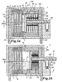
- Fig. 2a and Fig. 2b are only the essential differences compared to Embodiment according to Fig. 1a and Fig. 1b highlighted, reference numerals for the same elements.
- the current limiting device 2 is insulated and non-positively surrounded by a molded housing 20 a left-hand and a right-hand half-shell 201 and 202, respectively.
- the compressor rooms 61 are connected to a reservoir via a connection opening 25 26 in connection, which is preferably completely with liquid metal 7 is filled out.
- the storage container 26 is a (for example metallic) bellows executed in the area of an access opening 203 in the right-hand side Half-shell 202 tight with the outside of the right-hand electrode 222 is tightly connected.
- the free end face of the reservoir 26 is with a Tappet 264 connected, which slidably guided in a fixed bearing 245 is.
- the Storage container 26 At the extreme displacement of the plunger 264 to the right, the Storage container 26 its largest volume, which with a recording of Liquid metal 7 is connected from the compressor rooms 61, whereby the Liquid level 71 the smallest adjustable height Hmin above the connecting channels 5 occupies (Fig. 2a).
- the storage container 26 takes up its smallest volume, which is associated with a discharge of liquid metal 7 into the compressor rooms 61 is, whereby the liquid level 71 the largest adjustable height Hmax occupies over the connecting channels 5 (Fig. 2b).
- the plunger 264 is equipped with an adjustment scale 244. Between Hmin and Hmax can be any height of the liquid level 71 and thus continuously the nominal current factor of the current limiting device 2 by means of the adjusting device composed of the adjusting means 244 to 246 24 can be set.
- the present invention is not limited to the above-described embodiments limited, but also includes all within the meaning of the invention equivalent embodiments.
- This is how the current limiting device can be Modify 2, for example, so that for the reservoir 26 a cylinder-piston device is provided instead of a bellows becomes.
- Another possible training is that when using several current limiting devices 1 or 2 arranged in parallel a plunger device, the plunger 134 of the cylinder-piston devices 13 or the plungers 264 of the storage containers 26 are rigidly connected to one another are, here only a single setting device 14 or 24 for all Pole of the multi-pole current limiting device is required.
- the Current limiting device 1 can also be modified in such a way that with the elimination of the right-hand electrode 122, the copper strands 136 directly are connected to the right-hand connecting conductor 123.
Landscapes
- Compressor (AREA)
- Fuses (AREA)
- Emergency Protection Circuit Devices (AREA)
Description
- Figur 1a, b:
- im Längsschnitt eine erste Ausführungsform der erfindungsgemäßen Strombegrenzungseinrichtung;
- Figur 2a, b:
- im Längsschnitt eine zweite Ausführungsform der erfindungsgemäßen Strombegrenzungseinrichtung.
- 1
- Strombegrenzungseinrichtung
- 10
- Formgehäuse
- 101; 102
- Halbschalen
- 121; 122
- Elektroden
- 123
- Anschlussleiter
- 13
- Zylinder-Kolben-Einrichtung
- 131
- Zylinder
- 132
- Kolben
- 133
- Dichtring
- 134
- Stößel
- 135
- Rückstellfeder
- 136
- Kupfertitzen
- 14
- Einstellvorrichtung
- 141
- Rastkerben
- 142
- Rastfeder
- 143
- Zeiger
- 144
- Einstellskala
- 2
- Strombegrenzungseinrichtung
- 20
- Formgehäuse
- 201; 202
- Halbschalen
- 221; 222
- Elektroden
- 24
- Einstelivorrichtung
- 244
- Einstellskala
- 245
- Lager
- 246
- Klemmschraube
- 25
- Verbindungsöffnung
- 26
- Vorratsbehälter
- 264
- Stößel
- 3
- Dichtscheiben
- 41 ... 44
- Zwischenwände
- 5
- Verbindungskanäle
- 61; 62
- Verdichterräume
- 7
- Flüssigmetall
- 71
- Flüssigkeitsspiegel
- 8
- Linien
Claims (13)
- Selbsterholende Strombegrenzungseinrichtung mit Flüssigmetall, enthaltend Elektroden (121, 122; 221, 222) aus Festmetall zum Anschließen an einen zu schützenden Stromkreis und mehrere mit Flüssigmetall (7) teilweise aufgefüllte, zwischen den Elektroden (121, 122; 221, 222) hintereinander liegende Verdichterräume (61; 62), die durch druckfeste Isolierkörper (3, 10) und durch diese gehaltene isolierende Zwischenwände (41 ... 44) mit Verbindungskanälen (5) gebildet werden, dadurch gekennzeichnet, dass das das Flüssigmetall (7) beinhaltende Volumen der Verdichterräume (61; 62) in Verbindung mit einer Einstellvorrichtung (14; 24) veränderbar ist.
- Selbsterholende Strombegrenzungseinrichtung nach Anspruch 1, dadurch gekennzeichnet, dass wenigstens einer der Verdichterräume (61, 62) durch eine diesen Verdichterraum (62) abdichtende Zylinder-Kolben-Einrichtung (13) mitgebildet wird, wobei der wenigstens teilweise vom Flüssigmetall (7) bedeckte Kolben (132) mit einer von außen verstellbaren und feststellbaren Einstellvorrichtung (14) wirkverbunden ist.
- Selbsterholende Strombegrenzungseinrichtung nach Anspruch 2, dadurch gekennzeichnet, dass der Kolben (132) benachbart zu einer der Elektroden (122) angeordnet, mit dieser elektrisch leitend verbunden und senkrecht zur Erstreckung der Zwischenwände (41 ... 44) verschiebbar ist.
- Selbsterholende Strombegrenzungseinrichtung nach Anspruch 1, dadurch gekennzeichnet, dass wenigstens einer der Verdichterräume (61) mit einem mit Flüssigmetall (7) gefüllten Vorratsbehälter (26) veränderbaren Volumens verbunden ist, wobei der Vorratsbehälter (26) mit einer von außen verstellbaren und feststellbaren Einstellvorrichtung (24) wirkverbunden ist.
- Selbsterholende Strombegrenzungseinrichtung nach Anspruch 4, dadurch gekennzeichnet, dass der Vorratsbehälter (26) über eine Verbindungsöffnung (25) durch eine der Elektroden (222) in Verbindung mit dem an diese Elektrode (222) grenzenden Verdichterraum (61) steht.
- Selbsterholende Strombegrenzungseinrichtung nach Anspruch 4 oder 5, dadurch gekennzeichnet, dass der Vorratsbehälter eine den Verdichterraum abdichtende Zylinder-Kolben-Einrichtung ist.
- Selbsterholende Strombegrenzungseinrichtung nach Anspruch 4 oder 5, dadurch gekennzeichnet, dass der Vorratsbehälter (26) ein Faltenbalg ist.
- Selbsterholende Strombegrenzungseinrichtung nach einem der vorstehenden Ansprüche, dadurch gekennzeichnet, dass die Einstellvorrichtung (14; 24) mit einem Stößel (134; 264) verbunden ist.
- Selbsterholende Strombegrenzungseinrichtung nach einem der vorstehenden Ansprüche, dadurch gekennzeichnet, dass die Einstellvorrichtung (14; 24) über Rastmittel (141, 142, 143) oder Klemmmittel (245, 246) in mehreren Stellungen feststellbar ist.
- Selbsterholende Strombegrenzungseinrichtung nach einem der vorstehenden Ansprüche, dadurch gekennzeichnet, dass die Einstellvorrichtung (14; 24) mit einer Einstellskala (144; 244) für einzustellende Strombegrenzungscharakteristiken versehen ist.
- Selbsterholende Strombegrenzungseinrichtung nach Anspruch 10, dadurch gekennzeichnet, dass der Einstellskala (14) ein Zeiger (143) zugeordnet ist.
- Selbsterholende Strombegrenzungseinrichtung nach einem der vorstehenden Ansprüche, dadurch gekennzeichnet, dass die Einstellvorrichtung (14; 24) mit Einstellvorrichtungen benachbarter oder integrierter baugleicher Strombegrenzungseinrichtungen zusätzlicher Pole verbunden ist.
- Strombegrenzungseinrichtung nach einem der vorstehenden Ansprüche, dadurch gekennzeichnet, dass das Flüssigmetall (7) eine GaInSn-Legierung ist.
Applications Claiming Priority (3)
| Application Number | Priority Date | Filing Date | Title |
|---|---|---|---|
| DE19918451A DE19918451A1 (de) | 1999-04-23 | 1999-04-23 | Selbstholende Strombegrenzungseinrichtung mit Flüssigmetall |
| DE19918451 | 1999-04-23 | ||
| PCT/EP2000/003553 WO2000065618A2 (de) | 1999-04-23 | 2000-04-19 | Selbsterholende strombegrenzungseinrichtung mit flüssigmetall |
Publications (2)
| Publication Number | Publication Date |
|---|---|
| EP1173860A2 EP1173860A2 (de) | 2002-01-23 |
| EP1173860B1 true EP1173860B1 (de) | 2003-08-20 |
Family
ID=7905609
Family Applications (1)
| Application Number | Title | Priority Date | Filing Date |
|---|---|---|---|
| EP00926998A Expired - Lifetime EP1173860B1 (de) | 1999-04-23 | 2000-04-19 | Selbsterholende strombegrenzungseinrichtung mit flüssigmetall |
Country Status (4)
| Country | Link |
|---|---|
| US (1) | US6714115B1 (de) |
| EP (1) | EP1173860B1 (de) |
| DE (2) | DE19918451A1 (de) |
| WO (1) | WO2000065618A2 (de) |
Families Citing this family (4)
| Publication number | Priority date | Publication date | Assignee | Title |
|---|---|---|---|---|
| ATE373870T1 (de) * | 2003-07-10 | 2007-10-15 | Abb Research Ltd | Verfahren und vorrichtung zur strombegrenzung mit einem flüssigmetall-strombegrenzer |
| DE102006029693A1 (de) * | 2005-08-25 | 2007-03-01 | Siemens Ag | Selbstrückstellendes Strombegrenzungselement |
| WO2009055763A2 (en) * | 2007-10-26 | 2009-04-30 | Kowalik Daniel P | Micro-fluidic bubble fuse |
| CN112803356B (zh) * | 2021-03-02 | 2024-10-22 | 国网陕西省电力有限公司电力科学研究院 | 具有电流自转移功能的混合式直流断路器及其控制方法 |
Family Cites Families (19)
| Publication number | Priority date | Publication date | Assignee | Title |
|---|---|---|---|---|
| US1595061A (en) * | 1922-10-17 | 1926-08-03 | Valerius Johann | Electric cut-out |
| DE395284C (de) * | 1923-09-30 | 1924-05-19 | Johann Valerius | Elektrische Sicherung mit einem eigenen, die kapillare Bohrung enthaltenden Isoliereinsatz |
| CH106325A (de) * | 1923-10-15 | 1924-08-16 | Valerius Johann | Elektrische Sicherung. |
| US3369094A (en) * | 1966-07-15 | 1968-02-13 | Metcom Inc | Gallium metal contact switch |
| US3599137A (en) * | 1968-07-05 | 1971-08-10 | Mitsubishi Electric Corp | Current limiting device |
| US3644860A (en) * | 1969-04-24 | 1972-02-22 | Mitsubishi Electric Corp | Self-restoring current limiter |
| US3699489A (en) | 1970-03-28 | 1972-10-17 | Tokyo Shibaura Electric Co | Current limiting device |
| CH560462A5 (de) * | 1973-01-25 | 1975-03-27 | Mitsubishi Electric Corp | |
| US3806855A (en) * | 1973-04-30 | 1974-04-23 | Gen Electric | Vapor state current limiting device |
| US3991396A (en) * | 1975-05-07 | 1976-11-09 | General Electric Company | Electric circuit protector comprising parallel-connected liquid-metal current-limiting devices |
| DE2652506A1 (de) | 1976-11-18 | 1978-05-24 | Gec Elliott Automation Ltd | Elektrische hochstromvorrichtungen |
| SU922911A1 (ru) * | 1980-05-05 | 1982-04-23 | Kb Polt Inst Kujbysheva | Токоограничитель 1 |
| US4429295A (en) * | 1981-11-13 | 1984-01-31 | Electric Power Research Institute, Inc. | Variable impedance current limiting device |
| US4598332A (en) * | 1984-07-20 | 1986-07-01 | Westinghouse Electric Corp. | Current limiting apparatus utilizing multiple resistive parallel rails |
| SU1529303A1 (ru) | 1988-02-10 | 1989-12-15 | Институт Электродинамики Ан Усср | Жидкометаллический коммутационный аппарат |
| DD282778A5 (de) | 1989-04-26 | 1990-09-19 | Karl Marx Stadt Tech Hochschul | Stromgesteuerte abschaltvorrichtung |
| JP2854719B2 (ja) | 1991-04-10 | 1999-02-03 | 株式会社東芝 | 限流装置 |
| DE19914147A1 (de) * | 1999-03-29 | 2000-10-05 | Moeller Gmbh | Selbsterholende Strombegrenzungseinrichtung mit Flüssigmetall |
| DE10061715A1 (de) * | 2000-12-12 | 2002-06-13 | Basf Ag | Verfahren zur Herstellung von Homo- und Copolymeren des Isobutens |
-
1999
- 1999-04-23 DE DE19918451A patent/DE19918451A1/de not_active Withdrawn
-
2000
- 2000-04-19 WO PCT/EP2000/003553 patent/WO2000065618A2/de not_active Ceased
- 2000-04-19 US US10/031,255 patent/US6714115B1/en not_active Expired - Fee Related
- 2000-04-19 DE DE50003372T patent/DE50003372D1/de not_active Expired - Fee Related
- 2000-04-19 EP EP00926998A patent/EP1173860B1/de not_active Expired - Lifetime
Also Published As
| Publication number | Publication date |
|---|---|
| US6714115B1 (en) | 2004-03-30 |
| DE19918451A1 (de) | 2000-10-26 |
| EP1173860A2 (de) | 2002-01-23 |
| WO2000065618A2 (de) | 2000-11-02 |
| DE50003372D1 (de) | 2003-09-25 |
| WO2000065618A3 (de) | 2001-05-31 |
Similar Documents
| Publication | Publication Date | Title |
|---|---|---|
| WO2021007604A1 (de) | Stromtrenner | |
| DE69115635T2 (de) | SF6-Lastschalter mit eingebautem Kondensator | |
| EP0291762A2 (de) | Metallgekapselte, mit Druckgas gefüllte, mehrphasige Hochspannungsschaltanlage | |
| DE69619568T2 (de) | Lastschalter mit zwei Löschkammern je Pol | |
| DE69117399T2 (de) | Gaslastschalter | |
| EP0309386B1 (de) | Mehrpoliger Niederspannungs-Leistungsschalter mit einem Isolierstoffgehäuse und Lichtbogenlöschkammern | |
| DE69221675T2 (de) | Elektrische Schaltvorrichtung | |
| DE69323160T2 (de) | Öffnungs- und Schliessmechanismus für einen elektrischen Mittel- oder Hochspannungsschalter | |
| DE3105133C2 (de) | Gasisolierter Trennschalter | |
| DE19536673A1 (de) | Leistungsschalter | |
| DE69113349T2 (de) | Gasisolierter Schalter mit Selbstbeblasung. | |
| EP1173860B1 (de) | Selbsterholende strombegrenzungseinrichtung mit flüssigmetall | |
| DE3318226A1 (de) | Vakuumschalter mit doppelunterbrechung | |
| EP1173873B1 (de) | Selbsterholende strombegrenzungseinrichtung mit flüssigmetall | |
| EP1166308B1 (de) | Selbsterholende strombegrenzungseinrichtung mit flüssigmetall | |
| EP1047093B1 (de) | Selbsterholende Strombegrenzungseinrichtung mit Flüssigmetall | |
| EP1190429B1 (de) | Selbsterholende strombegrenzungseinrichtung mit flüssigmetall | |
| DE69207265T2 (de) | Varistor Einführvorrichtung, eingebaut in einem Hochspannungslastschalter | |
| EP1045419B1 (de) | Elektrodenanordnung für elektrische Einrichtungen mit Flüssigmetall | |
| EP1157401B1 (de) | Selbsterholende strombegrenzungseinrichtung mit flüssigmetall | |
| DE69522282T2 (de) | Lasttrennschalter | |
| DE3540474C2 (de) | ||
| EP1153406B1 (de) | Selbsterholende strombegrenzungseinrichtung mit flüssigmetall | |
| CH631029A5 (de) | Elektrische strombegrenzungsvorrichtung. | |
| DE10243993B3 (de) | Selbsterholende Strombegrenzungseinrichtung mit Flüssigmetall |
Legal Events
| Date | Code | Title | Description |
|---|---|---|---|
| PUAI | Public reference made under article 153(3) epc to a published international application that has entered the european phase |
Free format text: ORIGINAL CODE: 0009012 |
|
| 17P | Request for examination filed |
Effective date: 20011107 |
|
| AK | Designated contracting states |
Kind code of ref document: A2 Designated state(s): AT BE CH CY DE DK ES FI FR GB GR IE IT LI LU MC NL PT SE |
|
| GRAH | Despatch of communication of intention to grant a patent |
Free format text: ORIGINAL CODE: EPIDOS IGRA |
|
| GRAH | Despatch of communication of intention to grant a patent |
Free format text: ORIGINAL CODE: EPIDOS IGRA |
|
| GRAA | (expected) grant |
Free format text: ORIGINAL CODE: 0009210 |
|
| AK | Designated contracting states |
Designated state(s): CH DE FR IT LI |
|
| REG | Reference to a national code |
Ref country code: CH Ref legal event code: EP |
|
| REG | Reference to a national code |
Ref country code: IE Ref legal event code: FG4D Free format text: GERMAN |
|
| REF | Corresponds to: |
Ref document number: 50003372 Country of ref document: DE Date of ref document: 20030925 Kind code of ref document: P |
|
| REG | Reference to a national code |
Ref country code: CH Ref legal event code: NV Representative=s name: E. BLUM & CO. PATENTANWAELTE |
|
| REG | Reference to a national code |
Ref country code: IE Ref legal event code: FD4D |
|
| ET | Fr: translation filed | ||
| PLBE | No opposition filed within time limit |
Free format text: ORIGINAL CODE: 0009261 |
|
| STAA | Information on the status of an ep patent application or granted ep patent |
Free format text: STATUS: NO OPPOSITION FILED WITHIN TIME LIMIT |
|
| 26N | No opposition filed |
Effective date: 20040524 |
|
| REG | Reference to a national code |
Ref country code: CH Ref legal event code: PFA Owner name: MOELLER GMBH Free format text: MOELLER GMBH#HEIN-MOELLER-STRASSE 7-11#53115 BONN (DE) -TRANSFER TO- MOELLER GMBH#HEIN-MOELLER-STRASSE 7-11#53115 BONN (DE) |
|
| PGFP | Annual fee paid to national office [announced via postgrant information from national office to epo] |
Ref country code: DE Payment date: 20090422 Year of fee payment: 10 Ref country code: FR Payment date: 20090414 Year of fee payment: 10 Ref country code: IT Payment date: 20090427 Year of fee payment: 10 |
|
| PGFP | Annual fee paid to national office [announced via postgrant information from national office to epo] |
Ref country code: CH Payment date: 20090417 Year of fee payment: 10 |
|
| REG | Reference to a national code |
Ref country code: CH Ref legal event code: PL |
|
| REG | Reference to a national code |
Ref country code: FR Ref legal event code: ST Effective date: 20101230 |
|
| PG25 | Lapsed in a contracting state [announced via postgrant information from national office to epo] |
Ref country code: DE Free format text: LAPSE BECAUSE OF NON-PAYMENT OF DUE FEES Effective date: 20101103 Ref country code: CH Free format text: LAPSE BECAUSE OF NON-PAYMENT OF DUE FEES Effective date: 20100430 Ref country code: LI Free format text: LAPSE BECAUSE OF NON-PAYMENT OF DUE FEES Effective date: 20100430 |
|
| PG25 | Lapsed in a contracting state [announced via postgrant information from national office to epo] |
Ref country code: IT Free format text: LAPSE BECAUSE OF NON-PAYMENT OF DUE FEES Effective date: 20100419 |
|
| PG25 | Lapsed in a contracting state [announced via postgrant information from national office to epo] |
Ref country code: FR Free format text: LAPSE BECAUSE OF NON-PAYMENT OF DUE FEES Effective date: 20100430 |