EP1175356B1 - Verfahren und vorrichtung zur verwendung beim lagern und befördern von flüssigem und granulatartigem material - Google Patents
Verfahren und vorrichtung zur verwendung beim lagern und befördern von flüssigem und granulatartigem material Download PDFInfo
- Publication number
- EP1175356B1 EP1175356B1 EP00927499A EP00927499A EP1175356B1 EP 1175356 B1 EP1175356 B1 EP 1175356B1 EP 00927499 A EP00927499 A EP 00927499A EP 00927499 A EP00927499 A EP 00927499A EP 1175356 B1 EP1175356 B1 EP 1175356B1
- Authority
- EP
- European Patent Office
- Prior art keywords
- outer body
- liner
- container
- particulate matter
- expandable
- Prior art date
- Legal status (The legal status is an assumption and is not a legal conclusion. Google has not performed a legal analysis and makes no representation as to the accuracy of the status listed.)
- Expired - Lifetime
Links
- 239000013618 particulate matter Substances 0.000 title claims abstract description 31
- 239000012530 fluid Substances 0.000 title claims abstract description 13
- 238000000034 method Methods 0.000 title claims description 9
- 239000011800 void material Substances 0.000 claims abstract description 12
- 239000004800 polyvinyl chloride Substances 0.000 claims description 6
- 229920000915 polyvinyl chloride Polymers 0.000 claims description 5
- 239000000203 mixture Substances 0.000 claims description 4
- -1 polyethylene Polymers 0.000 claims description 4
- 239000004698 Polyethylene Substances 0.000 claims description 3
- QVGXLLKOCUKJST-UHFFFAOYSA-N atomic oxygen Chemical compound [O] QVGXLLKOCUKJST-UHFFFAOYSA-N 0.000 claims description 3
- 230000004888 barrier function Effects 0.000 claims description 3
- 229910052760 oxygen Inorganic materials 0.000 claims description 3
- 239000001301 oxygen Substances 0.000 claims description 3
- 229920000573 polyethylene Polymers 0.000 claims description 3
- 239000004814 polyurethane Substances 0.000 claims description 3
- 229920002635 polyurethane Polymers 0.000 claims description 3
- 239000007788 liquid Substances 0.000 description 26
- 239000000463 material Substances 0.000 description 10
- 230000003014 reinforcing effect Effects 0.000 description 2
- OKTJSMMVPCPJKN-UHFFFAOYSA-N Carbon Chemical compound [C] OKTJSMMVPCPJKN-UHFFFAOYSA-N 0.000 description 1
- 239000004677 Nylon Substances 0.000 description 1
- 239000004743 Polypropylene Substances 0.000 description 1
- 229910000831 Steel Inorganic materials 0.000 description 1
- XAGFODPZIPBFFR-UHFFFAOYSA-N aluminium Chemical compound [Al] XAGFODPZIPBFFR-UHFFFAOYSA-N 0.000 description 1
- 229910052782 aluminium Inorganic materials 0.000 description 1
- 239000004411 aluminium Substances 0.000 description 1
- 230000015572 biosynthetic process Effects 0.000 description 1
- 229910052799 carbon Inorganic materials 0.000 description 1
- 238000011109 contamination Methods 0.000 description 1
- 238000013016 damping Methods 0.000 description 1
- 239000000835 fiber Substances 0.000 description 1
- 238000005755 formation reaction Methods 0.000 description 1
- 239000007789 gas Substances 0.000 description 1
- 238000011065 in-situ storage Methods 0.000 description 1
- 238000009434 installation Methods 0.000 description 1
- 229920001778 nylon Polymers 0.000 description 1
- 229920003023 plastic Polymers 0.000 description 1
- 239000004033 plastic Substances 0.000 description 1
- 229920001155 polypropylene Polymers 0.000 description 1
- 239000010959 steel Substances 0.000 description 1
Images


Classifications
-
- B—PERFORMING OPERATIONS; TRANSPORTING
- B65—CONVEYING; PACKING; STORING; HANDLING THIN OR FILAMENTARY MATERIAL
- B65D—CONTAINERS FOR STORAGE OR TRANSPORT OF ARTICLES OR MATERIALS, e.g. BAGS, BARRELS, BOTTLES, BOXES, CANS, CARTONS, CRATES, DRUMS, JARS, TANKS, HOPPERS, FORWARDING CONTAINERS; ACCESSORIES, CLOSURES, OR FITTINGS THEREFOR; PACKAGING ELEMENTS; PACKAGES
- B65D90/00—Component parts, details or accessories for large containers
- B65D90/02—Wall construction
- B65D90/04—Linings
- B65D90/046—Flexible liners, e.g. loosely positioned in the container
- B65D90/048—Flexible liners, e.g. loosely positioned in the container comprising bracing straps
-
- B—PERFORMING OPERATIONS; TRANSPORTING
- B65—CONVEYING; PACKING; STORING; HANDLING THIN OR FILAMENTARY MATERIAL
- B65D—CONTAINERS FOR STORAGE OR TRANSPORT OF ARTICLES OR MATERIALS, e.g. BAGS, BARRELS, BOTTLES, BOXES, CANS, CARTONS, CRATES, DRUMS, JARS, TANKS, HOPPERS, FORWARDING CONTAINERS; ACCESSORIES, CLOSURES, OR FITTINGS THEREFOR; PACKAGING ELEMENTS; PACKAGES
- B65D2590/00—Component parts, details or accessories for large containers
- B65D2590/02—Wall construction
- B65D2590/04—Linings
- B65D2590/043—Flexible liners
- B65D2590/046—Bladders
Definitions
- This invention relates to an apparatus and method for use in the transportation of liquids or particulate matter in containers such as mobile containers, tankers, trailers, rigid van bodies or the like.
- the apparatus and method may be used for the transportation of liquids or particulate matter in ISO containers.
- U.S. 5,824,995 on which the preamble of claim 1 is based, discloses one attempted solution to this problem by providing apparatus for use in the transportation of fluid materials or particulate matter in a container for use with container handling equipment.
- the apparatus comprises a liner removably fittable in such a container to define a volume for containing a fluid material or particulate matter.
- the liner comprises a base portion and opposed end walls and opposed side walls extending upwardly from the base portion.
- Adjustable straps are provided to allow the volume of the liner to be varied to a limited extent to accommodate the relative differences in the densities of liquids to be transported. In order to avoid unacceptable dynamic forces being set up within the container, it is necessary to fully fill the liner to prevent the liquid moving around dynamically.
- the adjustable straps only allow adjustment of the volume within the liner to a limited extent. As a result, it is necessary for the liner to be substantially fully filled by liquid or particulate matter to prevent dynamic forces being set up during transportation. The liner is thus unsuitable for use in transporting smaller volumes of liquid in a relatively large container, such as a half-full load, whilst preventing unacceptable dynamic forces.
- Another problem is that operation of the adjustable straps is awkward and involves considerable manual effort to achieve. Consequently, the use of the apparatus is rendered inefficient and labour intensive.
- apparatus for transporting fluids or particulate matter in a container comprising an outer body defining an inner volume installable in use within the container and a liner fittable within the outer body, the liner being provided with a valve for loading and unloading the fluid or particulate matter, and the outer body being provided with one or more expandable chambers besides the inner volume, for reducing the volume of an internal void space between the outer body and the liner.
- the outer body comprises opposed basal and upper walls, opposed side walls and opposed end walls, the upper wall being provided with an opening through which the liner is insertable, the opening being closable in use by an attachable cover.
- the one or more expandable chambers are located in an upper portion of the outer body above the location of the liner when fitted within the outer body.
- the outer body comprises an expandable chamber extending along an upper edge of each opposed side wall.
- the outer body comprises an expandable chamber extending along an upper edge of at least one of the opposed end walls.
- the attachable cover comprises an expandable chamber.
- the at least one expandable chamber is/are an air bag provided with a valve for inflation by pump means.
- the at least one air chamber comprises a pressure release valve.
- the outer body is polyvinyl chloride or a blend of polyvinyl chloride and polyurethane.
- the liner is polyethylene or similar material.
- Preferably the liner is provided with a moisture and/or oxygen barrier layer.
- the apparatus further comprises one or more expandable chambers locatable in use between the outer body and the container.
- the present invention also provides a method of transporting fluids or particulate matter in a container, comprising the steps of installing an outer body defining an inner volume in the container, fitting a liner within the outer body, filling the liner with the fluid or particulate matter through a valve in the liner, and expanding one or more expandable chambers, besides the inner volume, to reduce the volume of an internal void space between the outer body and the liner.
- the void space is substantially reduced to zero.
- the expandable chambers are inflated by compressed air.
- the method further comprises the steps of locating one or more expandable chambers between the outer body and the container
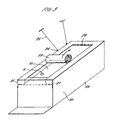
- the apparatus 1 of the present invention as shown in Figure 1 comprises a liner 10 for containing the liquid or particulate matter to be transported, and an outer body 20, surrounding the liner 10.
- the apparatus 1 is installed in a container 40, such as an ISO container, as shown in Figure 40.
- the liner 10 is of generally parallelepiped form comprising a base 12, top wall 15, opposed end walls 13 and opposed side walls 14.
- the liner 10 is made of polyethylene or a similar material which is flexible and impermeable to the liquid to be transported.
- the liner 10 may comprise an oxygen and/or moisture barrier on either its inner or outer surface.
- Different liners 10 may be utilised depending on the maximum volume of liquid or particulate matter that is likely to be required to be transported and the volume of the container in which the apparatus 1 is to be transported.
- the maximum volume of the liner 10 typically ranges from 1000 litres to 27000 litres. (According to the present invention it is not necessary to match exactly the maximum volume of the liner 10 with the volume of liquid or particulate matter to be transported, as will be explained below).
- a valve 11 is provided in the liner 10 to allow filling and emptying of liquid or particulate matter into or out of the liner 10.
- the valve 11 is situated in the top wall 15 of the liner 10 as shown in Figure 1.
- the valve 11 is situated at an upper, centre, or lower end of one of the end walls 13, as shown in Figure 4, so as to be easily accessible when the container end door 41 is opened.
- the liner 10 may be provided with a pressure relief valve (not shown) coupled to a manual drain tap by means of piping.
- the pressure relief valve acts to prevent a dangerous pressure build up within the liner 10, depending on the nature of the liquid transported.
- the outer body 20 is also of a generally parallelepiped form having a base wall 31, opposed end walls 32 and opposed side walls 33.
- the outer body 20 is made from a material such as polyvinyl chloride (PVC) or a blend of PVC and polyurethane or similar material.
- PVC polyvinyl chloride
- the outer body 20 is made from a material such as polyvinyl chloride (PVC) or a blend of PVC and polyurethane or similar material.
- An upper horizontal wall 35 of the outer body 20 opposed to the base 31 comprises a plurality of expandable air chambers 21.
- the air chambers are formed integrally with the material of the side walls 33.
- the air chambers 21 may comprise one or more replaceable or removable bladders in a lining.
- the use of bladders allows for easy and quick repair of any puncture in the air chambers 21.
- An opening 34 is defined between the air chambers 21 which is closed in use by a cover 23, as shown in Figure 4.
- One edge of the cover 23 is attached to one of the air chambers by means of a sewn seam 29.
- the other edges of the cover 23 are attachable to the remaining air chambers 21 by closure means 22.
- the closure means 22 is a zip closure.
- the closure means 22 comprises hoops attached to the material of the air chambers 21 and eyelets formed in the material of the cover 23. One or more cords, threaded through the hook and eyelet formations, are utilised to close the opening 34.
- the upper horizontal wall comprises two air chambers 21 which extend substantially along the entire length of the side walls 33 and one air chamber 21 which extends along one of the end walls 32.
- the cover 23 comprises a further air chamber 35 which extends along its length. When the cover 23 is closed the air chambers 21 integral with the side walls 33 and the air chamber 35 in the cover 23 cover substantially the entire upper horizontal wall of the outer body 20. The presence of the cover 23 gives greater structural integrity to the apparatus 1 when closed and protects the top wall 15 of the liner 10.
- the cover 23 may be designed to cover valve 11 when closed or alternatively be provided with an opening through which the valve 11 projects so as to be accessible when the cover 23 is closed.
- the outer body 20 may be provided with a series of hooks mounted on its outer face along each side wall 33.
- Each of the air chambers 21, 35 comprises an inflation valve 28.
- the air chambers 21, 35 and/or outer body 20 may be provided with reinforcing straps 27, 30 made from polypropylene and/or nylon if the nature of the load carried requires extra reinforcing of the apparatus 1.
- an outer surface of the cuter body 20 is provided with a series of support nooks 24 integrally mounted along each side wall 33.
- the outer body 20 is installed in the container 40 as shown in Figure 4, such as an ISO container.
- the outer body 20 is supported and held in position by means of elastic support cords 25, one end of which is attached to the support hooks 24 of the outer body 20 and the other end of which is attached to suitable anchor points in container 40.
- the closure means 22 is opened and the cover 23 of the outer body 20 is rolled back, as shown in Figure 3 to allow access to the inside of the outer body 20.
- the liner 10 is then placed into the outer body 20.
- Liquid or particulate matter is then loaded through valve 11 by known means. Once filling has been completed, the cover 23 of the outer body 20 is rolled back into position and the closure means 22 closed. Dependant on the quantity of liquid or particulate matter loaded into liner 10 and the size of the outer body 20, there may exist a void space inside the apparatus 1 between the liner 10 and the outer body 20.
- the air chambers 21, 35 are inflated using the inflation valves 28 to reduce the void space.
- the air chambers 21, 35 are inflated to a pressure in the range 1 to 50 psi gauge. Inflation causes the air chambers 21, 35 to expand to take up any excess volume between the liner 10 and the outer body 20.
- the void space is substantially reduced to zero.
- the air chambers 21 may be inflated with any suitable gas, vapour-liquid mixture or liquid.
- An over-pressure may be applied to the liner 10 by the air chambers 21, 35 to apply an additional damping force to the liquid or particulate matter stored therein and to increase the general rigidity of the apparatus 1.
- the apparatus 1 is then transported to its destination.
- the absence of a void space between the liner 10 and the outer body 20 together with the pressure applied to the liner 10 by the air chambers 21, 35 prevents excessive dynamic forces being set up within the container 40.
- the closure means 22 is opened and the cover 23 rolled back to reveal the valve 11 of the liner 10.
- the liquid or particulate matter may then be pumped out by known means.
- the cover 23 comprises an opening for the valve 11
- the liner 10 may be unloaded without first opening the closure means 22.
- the apparatus 1 may now be used to transport another load on the next journey of the container. If the same liquid or particulate matter is to be transported, then the same liner 10 may be used without any further action or a new liner 10 fitted. If a different liquid or particulate matter is to be transported, then either a new liner 10 may be used or the present liner 10 may be cleaned, either in situ within the outer body 20 or after removal from the outer body 20. In either case it is not necessary to remove the outer body 20 from the container. Consequently, less time is required before the next load may be transported.
- the apparatus 1 further comprises additional air chambers 50, in the form of inflatable bags, which are externally mounted on top of the cover 23 of the outer body 20 and optionally on the outer surface of the side walls 33.
- the air bags 50 may be permanently attached to the outer body 20 or removably attached by means of straps, hooks or similar means.
- the air bags 50 may be made from the same material as the outer body 20.
- This embodiment of the present invention may be used for the transportation of liquids or particulate matter in over-sized or unusually shaped containers such as rail freight containers.
- Rail freight containers are typically higher than road-going ISO containers.
- the additional air bags 50 are used to take up the additional space between the cover 23 of the outer body 20 and the roof of the freight container.
- the air bags 50 may be positioned only at each end of the freight container as shown in Figure 5 or may be positioned equi-spaced along the length of the freight container.
- the air bags 50 are inflated to a safe initial pressure in the range 2 to 50 psi gauge.
- Air bags may also be used mounted on the side walls 33 of the outer body 20 where the apparatus 1 is transported in a container of significantly greater width than the outer body 20.
- the outer body 20 may be provided with a support frame made of steel, plastic, carbon fibre or aluminium.
- the support frame may be utilised for aiding the installation of the outer body 20 in the container 40.
- the support frame may be collapsible when the apparatus 1 is not in use.
Landscapes
- Engineering & Computer Science (AREA)
- Mechanical Engineering (AREA)
- Packages (AREA)
- Filling Or Discharging Of Gas Storage Vessels (AREA)
- Air Transport Of Granular Materials (AREA)
- Details Of Rigid Or Semi-Rigid Containers (AREA)
- Compositions Of Macromolecular Compounds (AREA)
- Filling Or Emptying Of Bunkers, Hoppers, And Tanks (AREA)
Claims (16)
- Vorrichtung (1) zum Transportieren von Fluiden oder Partikelmaterial in einem Behälter (40), umfassend einen ein Innenvolumen definierenden Außenkörper (20), der im Gebrauch in dem Behälter (40) installierbar ist, sowie eine Auskleidung (10), die in den Außenkörper (20) einsetzbar ist, wobei die Auskleidung (10) mit einem Ventil (11) zum Beladen und Entladen des Fluids oder Partikelmaterials versehen ist, dadurch gekennzeichnet, dass der Außenkörper (20), neben dem Innenvolumen, mit einer oder mehreren aufweitbaren Kammern (21, 35) versehen ist, um das Volumen des inneren Leerraums zwischen dem Außenkörper (20) und der Auskleidung (10) zu reduzieren.
- Vorrichtung (1) nach Anspruch 1, worin der Außenkörper (20) gegenüberliegende Boden- (31) und Oberwände, gegenüberliegende Seitenwände (33) und gegenüberliegende Endwände (32) aufweist, wobei die Oberwand mit einer Öffnung (34) versehen ist, durch die die Auskleidung (10) einsetzbar ist, wobei im Gebrauch die Öffnung (34) durch eine anbringbare Abdeckung (23) verschließbar ist.
- Vorrichtung (1) nach Anspruch 1 oder Anspruch 2, worin die eine oder mehreren aufweitbaren Kammern (21, 35) an einem oberen Abschnitt des Außenkörpers (20) über dem Ort der Auskleidung (10) angeordnet sind, wenn diese in den Außenkörper (20) eingesetzt ist.
- Vorrichtung (1) nach Anspruch 3, worin der Außenkörper (20) eine aufweitbare Kammer (21) aufweist, die sich entlang einem Oberrand jeder gegenüberliegenden Seitenwand (33) erstreckt.
- Vorrichtung (1) nach Anspruch 3 oder Anspruch 4, worin der Außenkörper (20) eine aufweitbare Kammer (21) aufweist, die sich entlang einem Oberrand zumindest einer der gegenüberliegenden Endwände (32) erstreckt.
- Vorrichtung (1) nach einem der Ansprüche 3 bis 5, worin die anbringbare Abdeckung (23) eine aufweitbare Kammer aufweist.
- Vorrichtung (1) nach einem der vorhergehenden Ansprüche, worin die zumindest eine aufweitbare Kammer (21, 35) ein Luftsack ist, der mit einem Ventil (28) zum Aufpumpen durch Pumpenmittel versehen ist.
- Vorrichtung (1) nach Anspruch 7, worin die zumindest eine Luftkammer (21, 35) ein Druckablassventil aufweist.
- Vorrichtung (1) nach einem der vorhergehenden Ansprüche, worin der Außenkörper (20) Polyvinylchlorid oder ein Gemisch von Polyvinylchlorid und Polyurethan ist.
- Vorrichtung (1) nach einem der vorhergehenden Ansprüche, worin die Auskleidung (10) Polyethylen ist.
- Vorrichtung (1) nach einem der vorhergehenden Ansprüche, worin die Auskleidung (10) mit einer Feuchtigkeits- und/oder Sauerstoffbarriereschicht versehen ist.
- Vorrichtung (1) nach einem der vorhergehenden Ansprüche, die ferner eine oder mehrere aufweitbare Kammern (50) aufweist, die im Gebrauch zwischen dem Außenkörper (20) und dem Behälter (40) anordenbar sind.
- Verfahren des Transportierens von Fluiden oder Partikelmaterial in einem Behälter (40), das die Schritte umfasst: Installieren eines ein Innenvolumen definierenden Außenkörpers (20) in dem Behälter (40), Einsetzen einer Auskleidung (10) in den Außenkörper (20), Befüllen der Auskleidung (10) mit Fluid oder Partikelmaterial durch ein Ventil (11) in der Auskleidung (10) und Aufweiten einer oder mehrerer aufweitbarer Kammern neben dem innenvolumen (21, 35), um das Volumen des inneren Leerraums zwischen dem Außenkörper (20) und der Auskleidung (10) zu reduzieren.
- Verfahren nach Anspruch 13, worin der Leerraum im Wesentlichen auf null reduziert wird.
- Verfahren nach Anspruch 13 oder Anspruch 14, worin die aufweitbaren Kammern (21, 35) durch Druckluft aufgepumpt werden.
- Verfahren nach einem der Ansprüche 13 bis 15, das ferner die Schritte umfasst, eine oder mehrere aufweitbare Kammern (50) zwischen dem Außenkörper (20) und dem Behälter (10) anzuordnen.
Applications Claiming Priority (3)
| Application Number | Priority Date | Filing Date | Title |
|---|---|---|---|
| GB9910296A GB2349633B (en) | 1999-05-04 | 1999-05-04 | Apparatus and method for use in the transportation of fluids and particulate matter |
| GB9910296 | 1999-05-04 | ||
| PCT/GB2000/001710 WO2000066461A1 (en) | 1999-05-04 | 2000-05-04 | Apparatus and method for use in the transportation of fluids and particulate matter |
Publications (2)
| Publication Number | Publication Date |
|---|---|
| EP1175356A1 EP1175356A1 (de) | 2002-01-30 |
| EP1175356B1 true EP1175356B1 (de) | 2003-03-05 |
Family
ID=10852778
Family Applications (1)
| Application Number | Title | Priority Date | Filing Date |
|---|---|---|---|
| EP00927499A Expired - Lifetime EP1175356B1 (de) | 1999-05-04 | 2000-05-04 | Verfahren und vorrichtung zur verwendung beim lagern und befördern von flüssigem und granulatartigem material |
Country Status (11)
| Country | Link |
|---|---|
| EP (1) | EP1175356B1 (de) |
| JP (1) | JP2002543010A (de) |
| CN (1) | CN1352615A (de) |
| AT (1) | ATE233706T1 (de) |
| AU (1) | AU752987B2 (de) |
| CA (1) | CA2372615A1 (de) |
| DE (1) | DE60001552T2 (de) |
| ES (1) | ES2193073T3 (de) |
| GB (1) | GB2349633B (de) |
| WO (1) | WO2000066461A1 (de) |
| ZA (1) | ZA200109068B (de) |
Families Citing this family (9)
| Publication number | Priority date | Publication date | Assignee | Title |
|---|---|---|---|---|
| US6626312B2 (en) | 2000-06-28 | 2003-09-30 | Javier Urzua Maturana | Storage bag |
| JP4381175B2 (ja) * | 2004-02-27 | 2009-12-09 | 富士フイルム株式会社 | 輸送タンク及び輸送方法 |
| JP2008056243A (ja) * | 2004-12-06 | 2008-03-13 | Nippon Riku-Un Sangyo Co Ltd | 液体もしくは粉体を入れた車載用タンクの輸送方法 |
| DE102007032017B4 (de) * | 2007-05-16 | 2011-01-27 | Bayer Materialscience Ag | Verfahren zum Befüllen und Entleeren von Transport-Containern mit Kunststoffgranulaten |
| CN105800194B (zh) * | 2016-01-22 | 2019-04-30 | 上海鸿研物流技术有限公司 | 中型散装容器及其自带的液体防晃系统 |
| DE102017115010B3 (de) * | 2017-07-05 | 2018-08-23 | Deutsche Institute Für Textil- Und Faserforschung Denkendorf | Vorrichtung zum Abdecken einer Beladungsöffnung eines Behälters und Behälter mit einer solchen Vorrichtung |
| CN110329669B (zh) * | 2017-07-25 | 2021-07-30 | 乐清市然景电气有限公司 | 可快速装卸的安全集装箱 |
| NL2021873B9 (en) | 2018-10-25 | 2020-07-21 | Mega Inliner Int Group Bv | Liquid stabilizing inliner for a tank container |
| CN116142059B (zh) * | 2023-04-20 | 2023-06-27 | 东营胜蓝石油科技开发有限公司 | 一种油田拉砂作业车 |
Family Cites Families (7)
| Publication number | Priority date | Publication date | Assignee | Title |
|---|---|---|---|---|
| EP0299056A4 (de) * | 1987-01-07 | 1989-05-11 | Susan Beaupre Covey | Verpackungssystem mittels druck. |
| WO1988009755A1 (en) * | 1987-06-02 | 1988-12-15 | Warren Neil Chick | Bulk material handling unit |
| GB2237559A (en) * | 1989-11-02 | 1991-05-08 | Joseph Patrick Dempsey | Lined containers |
| JPH0826388A (ja) * | 1994-07-14 | 1996-01-30 | Mitsubishi Heavy Ind Ltd | 容器内の液体のスロッシング防止装置 |
| GB2302862B (en) | 1995-07-04 | 1999-01-13 | Crestbury Limited | Apparatus for use in the transportation of fluid materials or particulate matter |
| JPH10157795A (ja) * | 1996-10-04 | 1998-06-16 | Mitsubishi Heavy Ind Ltd | 内部液体動揺抑制型タンク |
| DE19744359A1 (de) * | 1997-10-08 | 1998-06-25 | Daniel Grenzendorf | Transportsicherung |
-
1999
- 1999-05-04 GB GB9910296A patent/GB2349633B/en not_active Expired - Lifetime
-
2000
- 2000-05-04 CA CA002372615A patent/CA2372615A1/en not_active Abandoned
- 2000-05-04 EP EP00927499A patent/EP1175356B1/de not_active Expired - Lifetime
- 2000-05-04 CN CN00807206.XA patent/CN1352615A/zh active Pending
- 2000-05-04 WO PCT/GB2000/001710 patent/WO2000066461A1/en not_active Ceased
- 2000-05-04 AU AU45899/00A patent/AU752987B2/en not_active Ceased
- 2000-05-04 ES ES00927499T patent/ES2193073T3/es not_active Expired - Lifetime
- 2000-05-04 JP JP2000615306A patent/JP2002543010A/ja active Pending
- 2000-05-04 AT AT00927499T patent/ATE233706T1/de not_active IP Right Cessation
- 2000-05-04 DE DE60001552T patent/DE60001552T2/de not_active Expired - Lifetime
-
2001
- 2001-11-02 ZA ZA200109068A patent/ZA200109068B/xx unknown
Also Published As
| Publication number | Publication date |
|---|---|
| GB2349633A (en) | 2000-11-08 |
| WO2000066461A1 (en) | 2000-11-09 |
| JP2002543010A (ja) | 2002-12-17 |
| DE60001552D1 (de) | 2003-04-10 |
| GB2349633B (en) | 2002-07-10 |
| ATE233706T1 (de) | 2003-03-15 |
| GB9910296D0 (en) | 1999-06-30 |
| AU4589900A (en) | 2000-11-17 |
| ES2193073T3 (es) | 2003-11-01 |
| ZA200109068B (en) | 2002-08-28 |
| CN1352615A (zh) | 2002-06-05 |
| DE60001552T2 (de) | 2004-01-15 |
| CA2372615A1 (en) | 2000-11-09 |
| AU752987B2 (en) | 2002-10-03 |
| EP1175356A1 (de) | 2002-01-30 |
Similar Documents
| Publication | Publication Date | Title |
|---|---|---|
| US4966310A (en) | Collapsible storage container and method for storing matter | |
| US3980196A (en) | Lining of containers for bulk cargo | |
| US5595315A (en) | Bracing system for a liner for a cargo container | |
| US5152735A (en) | Bracing system for a liner for a cargo container | |
| US4124136A (en) | Container liner frame support kit | |
| US5222621A (en) | Modified flexible insert for a generally rectangular container | |
| US5040693A (en) | Liner for a cargo container and a method of installing a liner inside a cargo container | |
| US5181625A (en) | Liner for a cargo container | |
| US5824995A (en) | Apparatus for use in the transportation of fluid materials or particulate matter | |
| US5137170A (en) | Flexible insert and method of installation within a generally rectangular container | |
| US7506776B2 (en) | Braceless liner | |
| US4441627A (en) | Bag system for transportation of bulk liquids | |
| US4132310A (en) | Shipping system for liquids and powders | |
| US20060078412A1 (en) | Apparatus for storing material | |
| EP0116821B1 (de) | Faltbares Transportbehältersystem | |
| EP1175356B1 (de) | Verfahren und vorrichtung zur verwendung beim lagern und befördern von flüssigem und granulatartigem material | |
| NO339579B1 (no) | Transportanordning og fremgangsmåte for transport av fluid | |
| US20030197009A1 (en) | Reinforced bulk container liner | |
| US3514157A (en) | Apparatus for packing and handling shipments | |
| US20190255982A1 (en) | Lightweight transport, storage and delivery system | |
| US4909156A (en) | Bladder-tarp | |
| US3658205A (en) | Cargo containers | |
| AU693161B2 (en) | Collapsible container for hauling bulk materials | |
| WO1985004637A1 (en) | A device for final emptying of a container | |
| WO2007087079A2 (en) | Apparatus and method for filling void in an outer container having a liquid-containing flexible package held therein |
Legal Events
| Date | Code | Title | Description |
|---|---|---|---|
| PUAI | Public reference made under article 153(3) epc to a published international application that has entered the european phase |
Free format text: ORIGINAL CODE: 0009012 |
|
| 17P | Request for examination filed |
Effective date: 20011102 |
|
| AK | Designated contracting states |
Kind code of ref document: A1 Designated state(s): AT BE CH CY DE DK ES FI FR GB GR IE IT LI LU MC NL PT SE |
|
| AX | Request for extension of the european patent |
Free format text: AL;LT;LV;MK;RO;SI |
|
| GRAG | Despatch of communication of intention to grant |
Free format text: ORIGINAL CODE: EPIDOS AGRA |
|
| 17Q | First examination report despatched |
Effective date: 20020425 |
|
| GRAG | Despatch of communication of intention to grant |
Free format text: ORIGINAL CODE: EPIDOS AGRA |
|
| GRAH | Despatch of communication of intention to grant a patent |
Free format text: ORIGINAL CODE: EPIDOS IGRA |
|
| GRAH | Despatch of communication of intention to grant a patent |
Free format text: ORIGINAL CODE: EPIDOS IGRA |
|
| GRAA | (expected) grant |
Free format text: ORIGINAL CODE: 0009210 |
|
| AK | Designated contracting states |
Designated state(s): AT BE CH CY DE DK ES FI FR GR IE IT LI LU MC NL PT SE |
|
| PG25 | Lapsed in a contracting state [announced via postgrant information from national office to epo] |
Ref country code: BE Free format text: LAPSE BECAUSE OF FAILURE TO SUBMIT A TRANSLATION OF THE DESCRIPTION OR TO PAY THE FEE WITHIN THE PRESCRIBED TIME-LIMIT Effective date: 20030305 Ref country code: GR Free format text: LAPSE BECAUSE OF FAILURE TO SUBMIT A TRANSLATION OF THE DESCRIPTION OR TO PAY THE FEE WITHIN THE PRESCRIBED TIME-LIMIT Effective date: 20030305 Ref country code: FR Free format text: LAPSE BECAUSE OF FAILURE TO SUBMIT A TRANSLATION OF THE DESCRIPTION OR TO PAY THE FEE WITHIN THE PRESCRIBED TIME-LIMIT Effective date: 20030305 Ref country code: CH Free format text: LAPSE BECAUSE OF FAILURE TO SUBMIT A TRANSLATION OF THE DESCRIPTION OR TO PAY THE FEE WITHIN THE PRESCRIBED TIME-LIMIT Effective date: 20030305 Ref country code: AT Free format text: LAPSE BECAUSE OF FAILURE TO SUBMIT A TRANSLATION OF THE DESCRIPTION OR TO PAY THE FEE WITHIN THE PRESCRIBED TIME-LIMIT Effective date: 20030305 Ref country code: LI Free format text: LAPSE BECAUSE OF FAILURE TO SUBMIT A TRANSLATION OF THE DESCRIPTION OR TO PAY THE FEE WITHIN THE PRESCRIBED TIME-LIMIT Effective date: 20030305 Ref country code: FI Free format text: LAPSE BECAUSE OF FAILURE TO SUBMIT A TRANSLATION OF THE DESCRIPTION OR TO PAY THE FEE WITHIN THE PRESCRIBED TIME-LIMIT Effective date: 20030305 Ref country code: NL Free format text: LAPSE BECAUSE OF FAILURE TO SUBMIT A TRANSLATION OF THE DESCRIPTION OR TO PAY THE FEE WITHIN THE PRESCRIBED TIME-LIMIT Effective date: 20030305 |
|
| REG | Reference to a national code |
Ref country code: CH Ref legal event code: EP |
|
| REG | Reference to a national code |
Ref country code: IE Ref legal event code: FG4D |
|
| REF | Corresponds to: |
Ref document number: 60001552 Country of ref document: DE Date of ref document: 20030410 Kind code of ref document: P |
|
| PG25 | Lapsed in a contracting state [announced via postgrant information from national office to epo] |
Ref country code: CY Free format text: LAPSE BECAUSE OF FAILURE TO SUBMIT A TRANSLATION OF THE DESCRIPTION OR TO PAY THE FEE WITHIN THE PRESCRIBED TIME-LIMIT Effective date: 20030504 Ref country code: LU Free format text: LAPSE BECAUSE OF NON-PAYMENT OF DUE FEES Effective date: 20030504 |
|
| PG25 | Lapsed in a contracting state [announced via postgrant information from national office to epo] |
Ref country code: IE Free format text: LAPSE BECAUSE OF NON-PAYMENT OF DUE FEES Effective date: 20030505 |
|
| PG25 | Lapsed in a contracting state [announced via postgrant information from national office to epo] |
Ref country code: MC Free format text: LAPSE BECAUSE OF NON-PAYMENT OF DUE FEES Effective date: 20030531 |
|
| PG25 | Lapsed in a contracting state [announced via postgrant information from national office to epo] |
Ref country code: DK Free format text: LAPSE BECAUSE OF FAILURE TO SUBMIT A TRANSLATION OF THE DESCRIPTION OR TO PAY THE FEE WITHIN THE PRESCRIBED TIME-LIMIT Effective date: 20030605 Ref country code: SE Free format text: LAPSE BECAUSE OF FAILURE TO SUBMIT A TRANSLATION OF THE DESCRIPTION OR TO PAY THE FEE WITHIN THE PRESCRIBED TIME-LIMIT Effective date: 20030605 |
|
| PG25 | Lapsed in a contracting state [announced via postgrant information from national office to epo] |
Ref country code: PT Free format text: LAPSE BECAUSE OF FAILURE TO SUBMIT A TRANSLATION OF THE DESCRIPTION OR TO PAY THE FEE WITHIN THE PRESCRIBED TIME-LIMIT Effective date: 20030606 |
|
| NLV1 | Nl: lapsed or annulled due to failure to fulfill the requirements of art. 29p and 29m of the patents act | ||
| LTIE | Lt: invalidation of european patent or patent extension |
Effective date: 20030305 |
|
| REG | Reference to a national code |
Ref country code: CH Ref legal event code: PL |
|
| REG | Reference to a national code |
Ref country code: ES Ref legal event code: FG2A Ref document number: 2193073 Country of ref document: ES Kind code of ref document: T3 |
|
| PLBE | No opposition filed within time limit |
Free format text: ORIGINAL CODE: 0009261 |
|
| STAA | Information on the status of an ep patent application or granted ep patent |
Free format text: STATUS: NO OPPOSITION FILED WITHIN TIME LIMIT |
|
| EN | Fr: translation not filed | ||
| 26N | No opposition filed |
Effective date: 20031208 |
|
| REG | Reference to a national code |
Ref country code: IE Ref legal event code: MM4A |
|
| PGFP | Annual fee paid to national office [announced via postgrant information from national office to epo] |
Ref country code: DE Payment date: 20190726 Year of fee payment: 20 Ref country code: ES Payment date: 20190724 Year of fee payment: 20 Ref country code: IT Payment date: 20190730 Year of fee payment: 20 |
|
| REG | Reference to a national code |
Ref country code: DE Ref legal event code: R071 Ref document number: 60001552 Country of ref document: DE |
|
| REG | Reference to a national code |
Ref country code: ES Ref legal event code: FD2A Effective date: 20200826 |
|
| PG25 | Lapsed in a contracting state [announced via postgrant information from national office to epo] |
Ref country code: ES Free format text: LAPSE BECAUSE OF EXPIRATION OF PROTECTION Effective date: 20200505 |