EP1175817A1 - Vorrichtung zur hydraulischen Steuerung der Unterlenker eines Schleppers - Google Patents
Vorrichtung zur hydraulischen Steuerung der Unterlenker eines Schleppers Download PDFInfo
- Publication number
- EP1175817A1 EP1175817A1 EP01111724A EP01111724A EP1175817A1 EP 1175817 A1 EP1175817 A1 EP 1175817A1 EP 01111724 A EP01111724 A EP 01111724A EP 01111724 A EP01111724 A EP 01111724A EP 1175817 A1 EP1175817 A1 EP 1175817A1
- Authority
- EP
- European Patent Office
- Prior art keywords
- hydraulic cylinder
- hydraulic
- stage
- hydraulic cylinders
- tractor
- Prior art date
- Legal status (The legal status is an assumption and is not a legal conclusion. Google has not performed a legal analysis and makes no representation as to the accuracy of the status listed.)
- Granted
Links
- 239000012530 fluid Substances 0.000 description 14
- 230000006641 stabilisation Effects 0.000 description 13
- 238000011105 stabilization Methods 0.000 description 13
- 230000008878 coupling Effects 0.000 description 7
- 238000010168 coupling process Methods 0.000 description 7
- 238000005859 coupling reaction Methods 0.000 description 7
- 230000008901 benefit Effects 0.000 description 4
- 230000000087 stabilizing effect Effects 0.000 description 4
- 238000004519 manufacturing process Methods 0.000 description 3
- 230000000903 blocking effect Effects 0.000 description 2
- 230000008859 change Effects 0.000 description 2
- 238000010276 construction Methods 0.000 description 2
- 244000003416 Asparagus officinalis Species 0.000 description 1
- 235000005340 Asparagus officinalis Nutrition 0.000 description 1
- 238000010521 absorption reaction Methods 0.000 description 1
- 230000006978 adaptation Effects 0.000 description 1
- 230000004888 barrier function Effects 0.000 description 1
- 230000002349 favourable effect Effects 0.000 description 1
- 238000002955 isolation Methods 0.000 description 1
- 239000007788 liquid Substances 0.000 description 1
- 230000002265 prevention Effects 0.000 description 1
- 230000007480 spreading Effects 0.000 description 1
Images




Classifications
-
- A—HUMAN NECESSITIES
- A01—AGRICULTURE; FORESTRY; ANIMAL HUSBANDRY; HUNTING; TRAPPING; FISHING
- A01B—SOIL WORKING IN AGRICULTURE OR FORESTRY; PARTS, DETAILS, OR ACCESSORIES OF AGRICULTURAL MACHINES OR IMPLEMENTS, IN GENERAL
- A01B59/00—Devices specially adapted for connection between animals or tractors and agricultural machines or implements
- A01B59/04—Devices specially adapted for connection between animals or tractors and agricultural machines or implements for machines pulled or pushed by a tractor
- A01B59/041—Devices specially adapted for connection between animals or tractors and agricultural machines or implements for machines pulled or pushed by a tractor preventing or limiting side-play of implements
- A01B59/0415—Devices specially adapted for connection between animals or tractors and agricultural machines or implements for machines pulled or pushed by a tractor preventing or limiting side-play of implements by hydraulic or pneumatic means acting on the lower draft links
-
- Y—GENERAL TAGGING OF NEW TECHNOLOGICAL DEVELOPMENTS; GENERAL TAGGING OF CROSS-SECTIONAL TECHNOLOGIES SPANNING OVER SEVERAL SECTIONS OF THE IPC; TECHNICAL SUBJECTS COVERED BY FORMER USPC CROSS-REFERENCE ART COLLECTIONS [XRACs] AND DIGESTS
- Y02—TECHNOLOGIES OR APPLICATIONS FOR MITIGATION OR ADAPTATION AGAINST CLIMATE CHANGE
- Y02A—TECHNOLOGIES FOR ADAPTATION TO CLIMATE CHANGE
- Y02A40/00—Adaptation technologies in agriculture, forestry, livestock or agroalimentary production
- Y02A40/10—Adaptation technologies in agriculture, forestry, livestock or agroalimentary production in agriculture
- Y02A40/28—Adaptation technologies in agriculture, forestry, livestock or agroalimentary production in agriculture specially adapted for farming
Definitions
- the invention relates to a device for hydraulic control of the two Lower link of a device attachment device of a vehicle, in particular of a tractor, comprising two each associated with a lower link Side struts, each one by a first stop limited minimum length up to a limit limited by a second stop Maximum length can be changed over a difference length, each side strut has a hydraulic cylinder and an elastic one Has reset element.
- Such devices are on agricultural or forestry Vehicles, especially on tractors, generally known.
- devices for stabilizing the lower links of a three-point coupling used on a tractor that is purely mechanical without hydraulics work.
- These known devices usually consist of one or two mechanical struts in a previously manually set one Length a lateral pivoting of the lower links and a attached device can block. By manually loosening the Freedom can strive; H. the free pivoting of the lower links with the device connected, if necessary.
- the cylinders of the two Side struts are connected to each other by a connecting line connect.
- the connecting line is via a lockable feed line connected to an oil pump serving as a pressure source.
- an oil pump serving as a pressure source.
- the hydraulic fluid can also be used when the feed line is shut off still flow freely from one to the other cylinder, so that a lateral Possibility of pivoting the lower links and a coupled device preserved.
- the stabilization of an attached one is in a position centered on the longitudinal axis of the tractor at least possible.
- it requires a manual change operation of the hydraulic valves and a corresponding sense of proportion of the driver.
- This means that the central locking of the attached device takes a relatively long time long and can not be an absolutely center-centered even with a larger amount of time Ensure what the position in certain driving situations Stability of the tractor and thus endanger the safety of the driver can.
- an extension of the Thread adjustment of the side struts to the category width of a narrower one Device when connecting another device a larger category width without having to adjust the Thread adjustment when the cylinder is depressurized is undesirable strong lateral limitation of the free range of the lower links, what for example in flight operations to a lateral overload and thus to Breakage of the device attachment.
- a hydraulic stabilization device which comprises a second pressure source, the pressurization of the hydraulic cylinders via an additional control valve the side struts regardless of pressurization of the hydraulic power lift made possible by the first pressure source.
- the device attachment device can also be used when the device is lowered Position of the implement attachment device and especially in the case of a side slope of the tractor are stabilized in the middle, but the aforementioned Disadvantages of the device known from DE 195 37 555 also occur here on.
- DE 197 37 318 and the associated Additional application DE 197 43 855 are devices for hydraulic Centering and stabilizing the device attachment device for devices of different types Broad categories known.
- DE 197 37 318 suggests this a device in which a side strut a two-stage hydraulic cylinder and the other side strut is a single stage hydraulic cylinder includes.
- DE 197 43 855 proposes a device in which both side struts each have a two-stage hydraulic cylinder include.
- each side strut also include a telescopic device that can be freely adjusted without pressure must have sufficient access to an attached device can be.
- the Lateral struts are not controlled to their maximum length by hydraulic control be extended.
- the maximum length of the side struts can only can be achieved in that on the freely movable end of the telescopic adjustment an external tensile force is applied.
- the respective lower link is not up to the maximum length of the associated side strut limited, most inward to Tractor longitudinal axis lying position can be pivoted what again to difficulties or an increased maneuvering effort with the Coupling different devices leads.
- the object of the present invention is a structurally simple, inexpensive device to be manufactured and easily handled at the beginning mentioned type to create the automatic without manual adjustment Centering of an attached device to the tractor's longitudinal axis with a simple stabilization option this centered Position guaranteed, and a high level of comfort when coupling different Devices through a completely hydraulically controllable swiveling the lower link over the entire length due to the difference in length of the side struts allowed predetermined angular range.
- each hydraulic cylinder with an outer Stage and at least one inner or middle stage carried out in several stages is that the total stroke of the hydraulic cylinder is equal to the differential length the respective side strut and that the stages of the hydraulic cylinder are designed such that when fully extended outer stage and with the inner stage fully retracted and at fully retracted middle steps, if any, the distance between the free ends of the two lower links of a first standard width devices to be installed.
- the main advantage is that when the two are pressurized Hydraulic cylinder attached by a common pressure source Device automatically in a centered absolutely to the longitudinal axis of the tractor Center position can be brought and when the pressure source is shut off stabilization of this central position in a particularly simple manner is achieved.
- the hydraulic fluid can despite the line Connection of the two hydraulic cylinders not freely from one to the other Cylinders flow because the one pushed out of a hydraulic cylinder Volume of liquid is greater than the volume of what other hydraulic cylinders could be added.
- additional Shut-off valves for each cylinder or for the connecting line are included not required for these functions.
- the device according to the invention is thus distinguished by a simple construction, inexpensive to manufacture and great security in particular through a high level of operating comfort for the driver of the tractor.
- Hydraulic cylinders are designed in two or three stages.
- the hydraulic cylinders can preferably be used as plunger cylinders or as single-acting pressure cylinders are designed. But it can also other cylinder designs, especially double-acting cylinders be used.
- a tension spring is formed within the multi-stage hydraulic cylinder is arranged.
- the spring in particular is not external Exposed to influences such as dirt or damage and a space-saving design is achieved.
- the Tension spring between the innermost cylinder step and the bottom of the Hydraulic cylinder to be effective.
- the hydraulic cylinders with an inner step and a middle step and an outer stage carried out in three stages are designed such that when fully extended outer stage and with the middle stage fully retracted and fully retracted inner step the distance between the free Ends of the two lower links of a first standard width different to be fitted Devices corresponds, and that with each fully extended outer stage and fully extended middle stage and at each fully retracted inner step the distance between the free Ends of the two lower links of a second standard width different equipments to be installed, which is less than the first standard width.
- a particularly simple stabilization of the center position can then be achieved if a circuit arrangement is provided with which both Hydraulic cylinders with each other via a connecting line are connectable, the hydraulic cylinder and the connecting line from Pressure sources and pressure sinks can be shut off.
- the hydraulic fluid despite the line connection of the both hydraulic cylinders do not flow freely from one cylinder to the other, so that the attached device is locked in the centered position or remains stabilized.
- those from AT 272721 or from Devices known from DE 195 37 555 are no additional devices Shut-off valves required.
- each hydraulic cylinder individually with line a pressure source, in particular with a common pressure source is connectable.
- each individual lower link is possible independently of the second lower link, so that in particular the coupling of a device from a single one Person can be carried out from the tractor seat.
- a circuit arrangement is preferably to be provided with which both Hydraulic cylinder individually or together with a pressure sink or with the hydraulic fluid tank of the tractor can be connected by line.
- valves of the circuit arrangement can be actuated electromagnetically.
- a remote control device can be provided with which the Valves of the circuit arrangement are controllable.
- sensors for detecting the vertical and / or horizontal position of the implement attachment device of the Tractor are provided, the signals to a control unit Control of the circuit arrangement or to a display device to transfer.
- the pressure source or sources with a Pressure limiting device may be provided.
- the hydraulic cylinders can advantageously have a common one or each with a separate flow restriction device, in particular be provided with a flow control valve. This allows the Retraction and extension speed of the cylinders and thus the swiveling speed the lower link is variably adjusted, especially limited become.
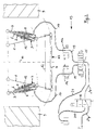
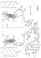
- the device shown in all figures is used for electro-hydraulic Control of the two lower links 1 of a three-point device mounting device, the directly or indirectly via a mounting device at the rear a tractor, not shown, is arranged. It comprises two Side struts 2, each associated with a lower link 1, the a pivoting range S is pivotable. Both side struts 2 are in essentially each from a single-acting hydraulic cylinder 3, the is designed as a three-stage telescopic cylinder. Both hydraulic cylinders 3 are constructed identically as a plunger cylinder and each have one Tension spring 4, which acts as an elastic return element within the Hydraulic cylinder 3 is arranged. The tension spring 4 extends between the inner step 5 and the bottom of the hydraulic cylinder 3.
- the hydraulic cylinders 3 each include an inner step 5, which in a middle stage 6 is stored.
- the middle level 6 is again in one outer stage 7 stored.
- the outer stage 7 is finally in the housing 8 of the hydraulic cylinder 3 mounted.
- the length the side struts 2 can be varied over a relatively large difference in length, whereby a large pivoting range S of the lower link 1 is reached.
- the Swivel range S extends from a relatively short distance from the rear wheels 9 of the tractor to almost the longitudinal axis 10 of the Tractor.
- Both side struts 2 can each have a length of one through the inner stops 11 of the individual cylinder stages 5, 6, 7 limited minimum length L1 to one through the outer stops 12 of the cylinder stages 5, 6, 7 limited maximum length L2 changed over a difference length become.
- this difference length L2-L1 is identical to that Total stroke of a hydraulic cylinder 3.
- stages 5, 6, 7 of hydraulic cylinders 3 are designed that with each fully extended outer stage 7 and each fully retracted middle level 6 and fully retracted inner level 5 the distance A3 between the free ends of the two lower links 1 of a larger standard width K3 different devices G to be fitted.
- the standardized width K3 show various attachments in Category 3.
- the adaptation the distance A3 to the standard width K3 allows automatic and backlash-free centering of an attached device G and the simple one Blocking the lower link 1 or the associated simple Stabilization of the attached device G without manual Adjustments are necessary.
- stages 5, 6, 7 of hydraulic cylinders 3 are also designed in such a way that with each fully extended outer stage 7 and completely extended middle level 6 and in each case fully retracted inner level 5 the distance A2 between the free ends of the two lower links 1 a smaller standard width K2 of other devices to be attached equivalent.
- the hydraulic circuit arrangement shown in Figures 1, 2, 4, 5 and 6 13 comprises a total of four electromagnetically actuated valves 14a, 14b, 15 and 16. While the valves 14a and 14b in the in the Arrangements shown in the drawings are arranged in lines 17, they can advantageously also directly in alternative embodiments be arranged on the pressure medium connections 18 of the hydraulic cylinders 3. In this way, on the one hand, the production of a relatively complex one Control blocks can be avoided and on the other hand can also with one Breakage of the lines 17 a stabilization or locking of the lower link 1 can be reached in their respective positions when the valves 14a and / or 14b are blocked.
- the two hydraulic cylinders 3 are line-wise via lines 17, respectively connected to a shut-off valve 14a or 14b.
- Each valve 14a or 14b enables the connection to the in a first switching position pressure source formed by a pump P of the tractor for extending of the respective hydraulic cylinder 3 ( Figure 1 and Figure 2) or to the tank T of the hydraulic fluid pressure sink to retract of the respective hydraulic cylinder 3 ( Figure 4).
- In the second switch position enables each valve 14a or 14b to shut off the respective one Hydraulic cylinder 3 for locking the respective side strut 2 or Stabilization of an attached device G (valve 14a in Figure 6).
- the Valves 14a and 14b are designed as seat valves, which makes them special high tightness and thus a particularly secure stabilization or locking is achievable.
- the valves 14a and 14b are switched so that they are closed when de-energized, as this operating state is mostly used.
- the two valves 14a and 14b are each connected to one via the lines 19 Connection of a valve 15 connected, which is designed as a 4/3-way valve.
- the valve 15 serves as a control valve for controlling the device and is so switched that the two hydraulic cylinders 3 both in the de-energized state with each other as well as with the pump P ( Figure 1 and Figure 2) or with the Tank T ( Figure 4) are connected. Under the influence of current, a Hydraulic cylinder 3 connected to the pump P while the other Hydraulic cylinder 3 is connected to the tank T ( Figure 5). So it can Device attachment device with simultaneous opening of the valves 14a and 14b be pivoted sideways.
- a third connection of the valve 15 is via a line 20 to the valve 16 connected, which is designed as a 3/2-way valve.
- the valve 16 serves as Selector valve to the pressure medium supply through the pump P if necessary to separate and connect the valve 15 to the tank T ( Figure 4).
- the valve 16 is switched so that the valve 15 in the de-energized state via a line 20p with the pump P and under the influence of current via a Line 20t is connected to the tank T.
- Isolation valve 16 is also designed as a seat valve.
- the fourth connection of the valve 15 is connected via a line 21 to the Tank T connected. Hydraulic fluid can flow out via this line 21 a hydraulic cylinder 3 are discharged when the associated Lower link 1 is pivoted outwards.
- both lower links can 1 can be pivoted or locked individually.
- Valves 15 and 16 are in the de-energized state, with both valves 14a and 14b are connected to the pump P via the valve 15.
- the valve 14a is also in the de-energized state, so that the left lower link 1 is blocked.
- the valve 14b is open under the influence of current, so that the the right hydraulic cylinder 3 extends and the right lower link 1 inwards is pivoted.
- valve 22 In the circuit arrangement 13 'shown in FIG. 3, one functions as a 3/2-way valve executed valve 22 as a control valve. In the illustrated de-energized switching position, both hydraulic cylinders 3 are in line connected with each other. This line connection over the Lines 17 and 19 and via the valve 22 is both from the Pump P and shut off from the tank T. This allows one to do so set position of an attached device G, in particular a centered center position, without further pressure supply by pump P be stabilized because the hydraulic fluid despite the line Connection 17, 19 due to the different widths of the cylinder stages 5, 6, 7 cannot flow freely from one to the other hydraulic cylinder 3.
- valve 22 would also have the Control positions of the valve 15 from the previously described FIGS. 1, 2 and can run 4 to 6.
- valves 23 are in the shown Embodiment designed as a 3/3-way valves, with a first valve connection each with the lines 17 and above with the hydraulic cylinders 3 is connected.
- the second and third valve connections are over Lines 24 and 25 are each connected in terms of lines. additionally is a connection line 24 also with the pump P and the other Connection line 25 also connected to the tank T.
- the valves 23 are designed such that all in a first switching position Valve connections are shut off, thereby stabilizing or Blocking the respectively set positions of an attached device G or the lower link 1 is reached.
- a second switching position of the Valve 23 is the first valve connection via the second valve connection the connecting line 24 and thus connected to the pump P, the third valve connection remains blocked.
- the third switch position of the Valve 23 is the first valve connection via the third valve connection with the Connection line 25 and thus connected to the tank T, the second valve connection remains blocked.
- a shut-off valve can be arranged to the simple way to switch the stabilization according to Figure 3.
- All valves 14a, 14b, 15, 16, 22 and 23 can be electromagnetic Valves can be controlled by a single control unit.
- the Control unit also via sensors information about the vertical Height position and / or over the horizontal side position of one or both Lower link 1 and / or that not shown in the drawings Main link of the three-point implement attachment device received.
Landscapes
- Life Sciences & Earth Sciences (AREA)
- Zoology (AREA)
- Engineering & Computer Science (AREA)
- Mechanical Engineering (AREA)
- Soil Sciences (AREA)
- Environmental Sciences (AREA)
- Lifting Devices For Agricultural Implements (AREA)
- Fluid-Pressure Circuits (AREA)
Abstract
Description
- Figur 1:
- Schematische Darstellung einer erfindungsgemäßen Vorrichtung mit einem angebauten Gerät einer größeren Kategoriebreite, mit einer hydraulischen Schaltungsanordnung, die sich in einer Stellung befindet, bei der eine Mittenzentrierung des Gerätes herbeigeführt wird,
- Figur 2:
- Schematische Darstellung der Vorrichtung und der Schaltungsanordnung aus Figur 1 mit einem angebauten Gerät einer kleineren Kategoriebreite, wobei ebenfalls eine Mittenzentrierung des Gerätes herbeigeführt wird,
- Figur 3:
- Schematische Darstellung der Vorrichtung aus Figur 1 mit einem angebauten Gerät und mit einer zweiten hydraulischen Schaltungsanordnung, die sich in einer Stellung befindet, bei der die mittenzentrierte Position des Gerätes stabilisiert ist,
- Figur 4:
- Schematische Darstellung der Vorrichtung und der Schaltungsanordnung aus Figur 1 mit einem angebauten Gerät, wobei sich die Schaltungsanordnung in einer Stellung befindet, bei der das Gerät im Freigang frei hin und her schwenken kann,
- Figur 5:
- Schematische Darstellung der Vorrichtung und der Schaltungsanordnung aus Figur 1 mit einem angebauten Gerät, wobei sich die Schaltungsanordnung in einer Stellung befindet, bei der das Gerät auf eine Seite verschwenkt wird,
- Figur 6:
- Schematische Darstellung der Vorrichtung und der Schaltungsanordnung aus Figur 1 ohne angebautes Gerät, wobei sich die Schaltungsanordnung in einer Stellung befindet, bei der beide Unterlenker einzeln verschwenkbar oder verriegelbar sind, und
- Figur 7:
- Schematische Darstellung der Vorrichtung aus Figur 1 mit einem angebauten Gerät und mit einer dritten hydraulischen Schaltungsanordnung, die sich in einer Stellung befindet, bei der eine Mittenzentrierung des Gerätes herbeigeführt wird.
- 1
- Unterlenker
- 2
- Seitenstrebe
- 3
- Hydraulikzylinder
- 4
- Zugfeder
- 5
- innere Stufe
- 6
- mittlere Stufe
- 7
- äußere Stufe
- 8
- Gehäuse
- 9
- Hinterrad
- 10
- Längsachse
- 11
- innere Anschläge
- 12
- äußere Anschläge
- 13
- Schaltungsanordnung
- 14
- Ventil (Absperrventile 14a und 14b)
- 15
- Ventil (4/3-Wege-Steuerventil)
- 16
- Ventil (3/2-Wege-Vorwahlventil)
- 17
- Leitung
- 18
- Druckmittelanschluß
- 19
- Leitung
- 20
- Leitung
- 20p
- Leitung
- 20t
- Leitung
- 21
- Leitung
- 22
- Ventil (3/2-Wege-Steuerventil)
- 23
- Ventil (3/3-Wege-Stuerventil)
- 24
- Leitung
- 25
- Leitung
- G
- Gerät
- L1
- Minimallänge
- L2
- Maximallänge
- A2
- kleinerer Abstand
- A3
- größerer Abstand
- K2
- kleinere Standardbreite
- K3
- größere Standardbreite
- P
- Pumpe
- T
- Tank
Claims (17)
- Vorrichtung zur hydraulischen Steuerung der beiden Unterlenker einer Geräteanbaueinrichtung eines Fahrzeugs, insbesondere eines Schleppers, umfassend zwei jeweils einem Unterlenker zugeordnete Seitenstreben, die jeweils von einer durch einen ersten Anschlag begrenzten Minimallänge bis zu einer durch einen zweiten Anschlag begrenzten Maximallänge über eine Differenzlänge längenveränderbar sind, wobei jede Seitenstrebe einen Hydraulikzylinder und ein elastisches Rückstellelement aufweist,
dadurch gekennzeichnet,daß jeder Hydraulikzylinder (3) mit einer äußeren Stufe (7) und mindestens einer inneren bzw. mittleren Stufe (5, 6) mehrstufig ausgeführt ist,daß der Gesamthub des Hydraulikzylinders (3) gleich der Differenzlänge der jeweiligen Seitenstrebe (2) ist,und daß die Stufen (5, 6, 7) der Hydraulikzylinder (3) derart ausgebildet sind, daß bei jeweils vollständig ausgefahrener äußerer Stufe (7) und bei jeweils vollständig eingefahrener innerer Stufe (5) und bei vollständig eingefahrenen gegebenenfalls vorhandener mittlerer Stufen (6) der Abstand (A3) zwischen den freien Enden der beiden Unterlenker (1) einer ersten Standardbreite (K3) verschiedener anzubauender Geräte (G) entspricht. - Vorrichtung nach Anspruch 1, dadurch gekennzeichnet, daß die Hydraulikzylinder (3) zweistufig oder dreistufig ausgeführt sind.
- Vorrichtung nach Anspruch 1 oder 2, dadurch gekennzeichnet, daß die Hydraulikzylinder (3) als Plungerzylinder oder als einfach wirkende Druckzylinder ausgeführt sind.
- Vorrichtung nach einem der vorherigen Ansprüche, dadurch gekennzeichnet, daß das elastische Rückstellelement (4) durch eine Zugfeder gebildet ist, die innerhalb des mehrstufigen Hydraulikzylinders (3) angeordnet ist.
- Vorrichtung nach Anspruch 4, dadurch gekennzeichnet, daß die Zugfeder (4) zwischen der innersten Stufe (5) und dem Boden des Hydraulikzylinders (3) wirksam ist.
- Vorrichtung nach einem der vorherigen Ansprüche, dadurch gekennzeichnet, daß die Hydraulikzylinder (3) mit einer inneren Stufe (5) und einer mittleren Stufe (6) und einer äußeren Stufe (7) dreistufig ausgeführt sind und die Stufen (5, 6, 7) der Hydraulikzylinder (3) derart ausgebildet sind, daß bei jeweils vollständig ausgefahrener äußerer Stufe (7) und bei jeweils vollständig eingefahrener mittlerer Stufe (6) und vollständig eingefahrener innerer Stufe (5) der Abstand (A3) zwischen den freien Enden der beiden Unterlenker (1) einer ersten Standardbreite (K3) verschiedener anzubauender Geräte (G) entspricht, und daß bei jeweils vollständig ausgefahrener äußerer Stufe (7) und vollständig ausgefahrener mittlerer Stufe (6) und bei jeweils vollständig eingefahrener innerer Stufe (5) der Abstand (A2) zwischen den freien Enden der beiden Unterlenker (1) einer zweiten Standardbreite (K2) verschiedener anzubauender Geräte (G) entspricht, die geringer ist, als die erste Standardbreite (K3).
- Vorrichtung nach einem der vorherigen Ansprüche, dadurch gekennzeichnet, daß eine hydraulische Schaltungsanordnung (13, 13', 13") vorgesehen ist, mit der beide Hydraulikzylinder (3) gleichzeitig mit einer gemeinsamen Druckquelle (P) leitungsmäßig verbindbar sind.
- Vorrichtung nach Anspruch 7, dadurch gekennzeichnet, daß eine Schaltungsanordnung (13') vorgesehen ist, mit der beide Hydraulikzylinder (3) über eine Verbindungsleitung (17, 19) leitungsmäßig miteinander verbindbar sind, wobei die Hydraulikzylinder (3) und die Verbindungsleitung (17, 19) von Druckquellen (P) und Drucksenken (T) absperrbar sind.
- Vorrichtung nach einem der vorherigen Ansprüche, dadurch gekennzeichnet, daß eine Schaltungsanordnung (13, 13', 13") vorgesehen ist, mit der jeder Hydraulikzylinder (3) einzeln leitungsmäßig mit einer Druckquelle (P), insbesondere mit einer gemeinsamen Druckquelle (P), verbindbar ist.
- Vorrichtung nach Anspruch 9, dadurch gekennzeichnet, daß eine Schaltungsanordnung (13, 13', 13") vorgesehen ist, mit der jeder Hydraulikzylinder (3) einzeln, vorzugsweise mittels eines Sitzventils (14a, 14b), absperrbar ist.
- Vorrichtung nach einem der Ansprüche 7 bis 10, dadurch gekennzeichnet, daß eine Schaltungsanordnung (13, 13', 13") vorgesehen ist, mit der beide Hydraulikzylinder (3) einzeln oder gemeinsam mit einer Drucksenke (T) leitungsmäßig verbindbar sind.
- Vorrichtung nach einem der Ansprüche 7 bis 11, dadurch gekennzeichnet, daß Sensoren zur Erfassung der vertikalen und/oder horizontalen Position der Geräteanbaueinrichtung des Schleppers oder der Unterlenker (1) angeordnet sind, die Signale an eine Steuereinheit zur Steuerung der Schaltungsanordnung (13, 13', 13") liefern.
- Vorrichtung nach einem der vorherigen Ansprüche, dadurch gekennzeichnet, daß die Hydraulikzylinder (3) mit einer gemeinsamen oder jeweils mit einer separaten Durchflußbegrenzungseinrichtung, insbesondere mit einem Stromregelventil versehen sind.
- Vorrichtung nach einem der vorherigen Ansprüche, dadurch gekennzeichnet, daß sie zwei Unterlenker (1) einer Geräteanbaueinrichtung eines Schleppers umfaßt.
- Vorrichtung nach einem der vorherigen Ansprüche, dadurch gekennzeichnet, daß sie eine Montagevorrichtung zur Befestigung der beiden Unterlenker (1) und der beiden Seitenstreben (2) der Geräteanbaueinrichtung an einem Fahrzeug, insbesondere am Heck eines Schleppers umfaßt.
- Fahrzeug, insbesondere forstwirtschaftlicher- oder landwirtschaftlicher Schlepper, mit einer Geräteanbaueinrichtung zum Anbau von verschiedenen Geräten, dadurch gekennzeichnet, daß es eine Vorrichtung nach einem der vorherigen Ansprüche aufweist.
- Mehrstufiger Hydraulikzylinder, gekennzeichnet durch die Merkmale nach einem der vorherigen Ansprüche.
Applications Claiming Priority (2)
| Application Number | Priority Date | Filing Date | Title |
|---|---|---|---|
| DE10036188A DE10036188C1 (de) | 2000-07-24 | 2000-07-24 | Vorrichtung zur hydraulischen Steuerung der Unterlenker eines Schleppers |
| DE10036188 | 2000-07-24 |
Publications (2)
| Publication Number | Publication Date |
|---|---|
| EP1175817A1 true EP1175817A1 (de) | 2002-01-30 |
| EP1175817B1 EP1175817B1 (de) | 2014-01-01 |
Family
ID=7650141
Family Applications (1)
| Application Number | Title | Priority Date | Filing Date |
|---|---|---|---|
| EP01111724.9A Expired - Lifetime EP1175817B1 (de) | 2000-07-24 | 2001-05-15 | Vorrichtung zur hydraulischen Steuerung der Unterlenker eines Schleppers |
Country Status (2)
| Country | Link |
|---|---|
| EP (1) | EP1175817B1 (de) |
| DE (1) | DE10036188C1 (de) |
Cited By (1)
| Publication number | Priority date | Publication date | Assignee | Title |
|---|---|---|---|---|
| EP4275465A1 (de) * | 2022-05-09 | 2023-11-15 | Weber-Hydraulik GmbH | Hydraulische verstellvorrichtung |
Families Citing this family (2)
| Publication number | Priority date | Publication date | Assignee | Title |
|---|---|---|---|---|
| DE102006046329B4 (de) | 2006-09-28 | 2021-03-25 | Claas Saulgau Gmbh | Arbeitsfahrzeug mit einer Kupplungsvorrichtung zum Anhängen eines Arbeitsgerätes |
| DE102014113448A1 (de) * | 2014-09-17 | 2016-03-17 | Jürgen Wagner | Zugfahrzeug und Anhängevorrichtung für ein Anbaugerät |
Citations (8)
| Publication number | Priority date | Publication date | Assignee | Title |
|---|---|---|---|---|
| FR1364703A (fr) * | 1963-05-13 | 1964-06-26 | Vérin hydraulique perfectionné, notamment pour carrossiers | |
| AT272721B (de) | 1966-04-14 | 1969-07-25 | Troester A J Fa | Vorrichtung zum Ankuppeln eines oder beider Unterlenker einer Dreipunktkupplung eines landwirtschaftlichen Arbeitsgerätes an einen Schlepper und/oder zum Stabilisieren oder Dämpfen dieser Lenker |
| DE1557849A1 (de) * | 1966-08-09 | 1971-09-30 | Troester A J Fa | Vorrichtung zum Stabilisieren,vorzugsweise auch zum Ankuppeln der Unterlenker einer Schlepper-Dreipunktkupplung an ein landwirtschaftliches Arbeitsgeraet |
| DE19537555A1 (de) | 1995-10-09 | 1997-04-10 | Anton Mayer | Vorrichtung zur Seitenstabilisierung der Unterlenker einer Geräteanbauvorrichtung an einem landwirtschaftlichen Schlepper |
| DE19744328C1 (de) | 1997-10-08 | 1998-10-22 | Walterscheid Gmbh Gkn | Seitenstrebe für den Unterlenker eines Traktors |
| DE19744327C1 (de) | 1997-10-08 | 1998-10-22 | Walterscheid Gmbh Gkn | Vorrichtung zur Stabilisierung der Unterlenker eines Traktors |
| DE19737318A1 (de) | 1997-08-28 | 1999-03-11 | Rau Serta Hydraulik Gmbh | Vorrichtung zur automatischen Stabilisierung beider Unterlenker einer Geräteanbauvorrichtung an einem landwirtschaftlichen oder forstwirtschaftlichen Schlepper |
| DE19743855A1 (de) | 1997-08-28 | 1999-05-20 | Rau Serta Hydraulik Gmbh | Vorrichtung zur automatischen Stabilisierung bei der Unterlenker einer Geräteanbauvorrichtung an einem landwirtschaftlichen oder forstwirtschaftlichen Schlepper. Diese Stabilisierung erfolgt vollhydraulisch und garantiert die spielfreie Positionierung der Unterlenker in zentrierter Lage zur Schlepperlängsachse. Im drucklosen Zustand ermöglicht diese Vorrichtung den maximal möglichen Freigang der Unterlenker, d.h. bis kurz vor dem jeweiligen Hinterrad des Schleppers |
-
2000
- 2000-07-24 DE DE10036188A patent/DE10036188C1/de not_active Expired - Fee Related
-
2001
- 2001-05-15 EP EP01111724.9A patent/EP1175817B1/de not_active Expired - Lifetime
Patent Citations (8)
| Publication number | Priority date | Publication date | Assignee | Title |
|---|---|---|---|---|
| FR1364703A (fr) * | 1963-05-13 | 1964-06-26 | Vérin hydraulique perfectionné, notamment pour carrossiers | |
| AT272721B (de) | 1966-04-14 | 1969-07-25 | Troester A J Fa | Vorrichtung zum Ankuppeln eines oder beider Unterlenker einer Dreipunktkupplung eines landwirtschaftlichen Arbeitsgerätes an einen Schlepper und/oder zum Stabilisieren oder Dämpfen dieser Lenker |
| DE1557849A1 (de) * | 1966-08-09 | 1971-09-30 | Troester A J Fa | Vorrichtung zum Stabilisieren,vorzugsweise auch zum Ankuppeln der Unterlenker einer Schlepper-Dreipunktkupplung an ein landwirtschaftliches Arbeitsgeraet |
| DE19537555A1 (de) | 1995-10-09 | 1997-04-10 | Anton Mayer | Vorrichtung zur Seitenstabilisierung der Unterlenker einer Geräteanbauvorrichtung an einem landwirtschaftlichen Schlepper |
| DE19737318A1 (de) | 1997-08-28 | 1999-03-11 | Rau Serta Hydraulik Gmbh | Vorrichtung zur automatischen Stabilisierung beider Unterlenker einer Geräteanbauvorrichtung an einem landwirtschaftlichen oder forstwirtschaftlichen Schlepper |
| DE19743855A1 (de) | 1997-08-28 | 1999-05-20 | Rau Serta Hydraulik Gmbh | Vorrichtung zur automatischen Stabilisierung bei der Unterlenker einer Geräteanbauvorrichtung an einem landwirtschaftlichen oder forstwirtschaftlichen Schlepper. Diese Stabilisierung erfolgt vollhydraulisch und garantiert die spielfreie Positionierung der Unterlenker in zentrierter Lage zur Schlepperlängsachse. Im drucklosen Zustand ermöglicht diese Vorrichtung den maximal möglichen Freigang der Unterlenker, d.h. bis kurz vor dem jeweiligen Hinterrad des Schleppers |
| DE19744328C1 (de) | 1997-10-08 | 1998-10-22 | Walterscheid Gmbh Gkn | Seitenstrebe für den Unterlenker eines Traktors |
| DE19744327C1 (de) | 1997-10-08 | 1998-10-22 | Walterscheid Gmbh Gkn | Vorrichtung zur Stabilisierung der Unterlenker eines Traktors |
Cited By (1)
| Publication number | Priority date | Publication date | Assignee | Title |
|---|---|---|---|---|
| EP4275465A1 (de) * | 2022-05-09 | 2023-11-15 | Weber-Hydraulik GmbH | Hydraulische verstellvorrichtung |
Also Published As
| Publication number | Publication date |
|---|---|
| EP1175817B1 (de) | 2014-01-01 |
| DE10036188C1 (de) | 2001-09-27 |
Similar Documents
| Publication | Publication Date | Title |
|---|---|---|
| EP0507232B1 (de) | Steuersystem für Schlepper mit angehängtem Arbeitsgerät | |
| EP0617881A1 (de) | Vorrichtung zum Verbinden eines Gerätes mit einem ziehenden Fahrzeug | |
| DE60130307T2 (de) | Ventileinheit mit Scheibenpaket für einen Hydraulikkreis | |
| EP1407650A1 (de) | Geräteschnittstelle zur Kopplung von Arbeitsgeräten an ein Arbeitsfahrzeug und Ventilanordnung | |
| EP0201046B1 (de) | Arbeitsgerät, insbesondere Bodenbearbeitungsgerät | |
| DE202004017743U1 (de) | Fahrsteuerschaltung für eine Arbeitsmaschine | |
| EP0387529A2 (de) | Flüssigkeitskreislauf mit einem Steuerventil | |
| DE3438353C2 (de) | ||
| DE69614776T2 (de) | Steuerventil für ein hydraulisches Lenksystem | |
| EP2016818B1 (de) | Hubwerk und Verfahren zum Ansteuern eines derartigen Hubwerks | |
| DE4028887C2 (de) | Hydraulische Steuereinrichtung | |
| AT409060B (de) | Vorrichtung zur stabilisierung der unterlenker eines traktors | |
| DE10036188C1 (de) | Vorrichtung zur hydraulischen Steuerung der Unterlenker eines Schleppers | |
| EP0182100B1 (de) | Hydraulische Steuereinrichtung | |
| DE19537555C2 (de) | Vorrichtung zur Seitenstabilisierung der Unterlenker einer Geräteanbaueinrichtung an einem landwirtschaftlichen Schlepper | |
| DE2718190C2 (de) | Hydraulische Kolben-Zylinder-Anordnung zum Kippen des Fahrerhauses eines Lastkraftwagens | |
| EP4275465B1 (de) | Hydraulische verstellvorrichtung | |
| DE2729766C2 (de) | Hydrostatische Fahrzeug-Lenkhilfe | |
| EP3348430B1 (de) | Hydraulisches dämpfungssystem und gelenkfahrzeug mit einem derartigen dämpfungssystem | |
| EP3756435B1 (de) | Vorrichtung zur einstellung eines hydraulischen oberlenkers | |
| DE19737318C2 (de) | Vorrichtung zur automatischen Stabilisierung von zwei Unterlenkern einer Geräteanbaueinrichtung an einem landwirtschaftlichen oder forstwirtschaftlichen Schlepper | |
| DE19820377C1 (de) | Arbeitsfahrzeug mit kippbarer Fahrerplattform und Kippvorrichtung | |
| DE2751449B1 (de) | Vorrichtung zur Lage- und/oder Arbeitstiefenregelung an landwirtschaftlichen Maschinen,insbesondere fuer mit Ackerschleppern gekuppelte Anbaugeraete | |
| EP0164741B1 (de) | Prioritätsventil | |
| EP3942909A1 (de) | Anbaudrehpflug |
Legal Events
| Date | Code | Title | Description |
|---|---|---|---|
| PUAI | Public reference made under article 153(3) epc to a published international application that has entered the european phase |
Free format text: ORIGINAL CODE: 0009012 |
|
| AK | Designated contracting states |
Kind code of ref document: A1 Designated state(s): AT BE CH CY DE DK ES FI FR GB GR IE IT LI LU MC NL PT SE TR |
|
| AX | Request for extension of the european patent |
Free format text: AL;LT;LV;MK;RO;SI |
|
| 17P | Request for examination filed |
Effective date: 20020725 |
|
| AKX | Designation fees paid |
Free format text: AT BE CH CY DE DK ES FI FR GB GR IE IT LI LU MC NL PT SE TR |
|
| 17Q | First examination report despatched |
Effective date: 20040109 |
|
| GRAP | Despatch of communication of intention to grant a patent |
Free format text: ORIGINAL CODE: EPIDOSNIGR1 |
|
| STAA | Information on the status of an ep patent application or granted ep patent |
Free format text: STATUS: THE APPLICATION IS DEEMED TO BE WITHDRAWN |
|
| 18D | Application deemed to be withdrawn |
Effective date: 20050908 |
|
| GRAA | (expected) grant |
Free format text: ORIGINAL CODE: 0009210 |
|
| PUAC | Information related to the publication of a b1 document modified or deleted |
Free format text: ORIGINAL CODE: 0009299EPPU |
|
| AK | Designated contracting states |
Kind code of ref document: B1 Designated state(s): AT BE CH CY DE DK ES FI FR GB GR IE IT LI LU MC NL PT SE TR |
|
| B1DE | Publication of patent cancelled |
Effective date: 20131206 |
|
| DB1 | Publication of patent cancelled | ||
| REG | Reference to a national code |
Ref country code: CH Ref legal event code: EP Ref country code: NL Ref legal event code: GRER Effective date: 20140108 Ref country code: CH Ref legal event code: PK Free format text: DIE ERTEILUNG WURDE VOM EPA WIDERRUFEN. |
|
| REG | Reference to a national code |
Ref country code: IE Ref legal event code: FG4D Free format text: LANGUAGE OF EP DOCUMENT: GERMAN |
|
| REG | Reference to a national code |
Ref country code: AT Ref legal event code: REF Ref document number: 647183 Country of ref document: AT Kind code of ref document: T Effective date: 20140215 |
|
| REG | Reference to a national code |
Ref country code: CH Ref legal event code: PK Free format text: DIE ANMELDUNG GILT ALS VOR DER ERTEILUNG ALS ZURUECKGENOMMEN |