EP1176047A1 - Vorrichtung zum Führen und Verankern herausnehmbarer Fahrzeugsitze - Google Patents
Vorrichtung zum Führen und Verankern herausnehmbarer Fahrzeugsitze Download PDFInfo
- Publication number
- EP1176047A1 EP1176047A1 EP01420158A EP01420158A EP1176047A1 EP 1176047 A1 EP1176047 A1 EP 1176047A1 EP 01420158 A EP01420158 A EP 01420158A EP 01420158 A EP01420158 A EP 01420158A EP 1176047 A1 EP1176047 A1 EP 1176047A1
- Authority
- EP
- European Patent Office
- Prior art keywords
- slide
- flange
- axis
- hook
- transverse
- Prior art date
- Legal status (The legal status is an assumption and is not a legal conclusion. Google has not performed a legal analysis and makes no representation as to the accuracy of the status listed.)
- Granted
Links
- 238000004873 anchoring Methods 0.000 title claims description 8
- 238000000605 extraction Methods 0.000 claims description 9
- 238000004519 manufacturing process Methods 0.000 claims description 4
- 230000000149 penetrating effect Effects 0.000 claims description 3
- 238000005096 rolling process Methods 0.000 claims description 3
- 230000000903 blocking effect Effects 0.000 claims description 2
- 230000000694 effects Effects 0.000 claims 1
- 230000014759 maintenance of location Effects 0.000 claims 1
- 230000000717 retained effect Effects 0.000 claims 1
- 238000011084 recovery Methods 0.000 abstract 1
- 238000006073 displacement reaction Methods 0.000 description 7
- 240000000528 Ricinus communis Species 0.000 description 3
- 235000004443 Ricinus communis Nutrition 0.000 description 3
- 230000007547 defect Effects 0.000 description 2
- 238000009434 installation Methods 0.000 description 2
- 239000000523 sample Substances 0.000 description 2
- 240000008042 Zea mays Species 0.000 description 1
- 230000000295 complement effect Effects 0.000 description 1
- 230000001186 cumulative effect Effects 0.000 description 1
- 239000000463 material Substances 0.000 description 1
- 230000001681 protective effect Effects 0.000 description 1
Images


Classifications
-
- B—PERFORMING OPERATIONS; TRANSPORTING
- B60—VEHICLES IN GENERAL
- B60N—SEATS SPECIALLY ADAPTED FOR VEHICLES; VEHICLE PASSENGER ACCOMMODATION NOT OTHERWISE PROVIDED FOR
- B60N2/00—Seats specially adapted for vehicles; Arrangement or mounting of seats in vehicles
- B60N2/02—Seats specially adapted for vehicles; Arrangement or mounting of seats in vehicles the seat or part thereof being movable, e.g. adjustable
- B60N2/04—Seats specially adapted for vehicles; Arrangement or mounting of seats in vehicles the seat or part thereof being movable, e.g. adjustable the whole seat being movable
- B60N2/06—Seats specially adapted for vehicles; Arrangement or mounting of seats in vehicles the seat or part thereof being movable, e.g. adjustable the whole seat being movable slidable
- B60N2/08—Seats specially adapted for vehicles; Arrangement or mounting of seats in vehicles the seat or part thereof being movable, e.g. adjustable the whole seat being movable slidable characterised by the locking device
- B60N2/0831—Movement of the latch
- B60N2/0837—Movement of the latch pivoting
- B60N2/0843—Movement of the latch pivoting about a longitudinal axis
-
- B—PERFORMING OPERATIONS; TRANSPORTING
- B60—VEHICLES IN GENERAL
- B60N—SEATS SPECIALLY ADAPTED FOR VEHICLES; VEHICLE PASSENGER ACCOMMODATION NOT OTHERWISE PROVIDED FOR
- B60N2/00—Seats specially adapted for vehicles; Arrangement or mounting of seats in vehicles
- B60N2/005—Arrangement or mounting of seats in vehicles, e.g. dismountable auxiliary seats
- B60N2/015—Attaching seats directly to vehicle chassis
- B60N2/01508—Attaching seats directly to vehicle chassis using quick release attachments
- B60N2/01516—Attaching seats directly to vehicle chassis using quick release attachments with locking mechanisms
- B60N2/01525—Attaching seats directly to vehicle chassis using quick release attachments with locking mechanisms with locking elements expanding inside or under the vehicle floor or rail
- B60N2/01541—Attaching seats directly to vehicle chassis using quick release attachments with locking mechanisms with locking elements expanding inside or under the vehicle floor or rail using moving hooks
-
- B—PERFORMING OPERATIONS; TRANSPORTING
- B60—VEHICLES IN GENERAL
- B60N—SEATS SPECIALLY ADAPTED FOR VEHICLES; VEHICLE PASSENGER ACCOMMODATION NOT OTHERWISE PROVIDED FOR
- B60N2/00—Seats specially adapted for vehicles; Arrangement or mounting of seats in vehicles
- B60N2/005—Arrangement or mounting of seats in vehicles, e.g. dismountable auxiliary seats
- B60N2/015—Attaching seats directly to vehicle chassis
- B60N2/01508—Attaching seats directly to vehicle chassis using quick release attachments
- B60N2/01591—Attaching seats directly to vehicle chassis using quick release attachments with wheels coupled to the seat
-
- B—PERFORMING OPERATIONS; TRANSPORTING
- B60—VEHICLES IN GENERAL
- B60N—SEATS SPECIALLY ADAPTED FOR VEHICLES; VEHICLE PASSENGER ACCOMMODATION NOT OTHERWISE PROVIDED FOR
- B60N2/00—Seats specially adapted for vehicles; Arrangement or mounting of seats in vehicles
- B60N2/02—Seats specially adapted for vehicles; Arrangement or mounting of seats in vehicles the seat or part thereof being movable, e.g. adjustable
- B60N2/04—Seats specially adapted for vehicles; Arrangement or mounting of seats in vehicles the seat or part thereof being movable, e.g. adjustable the whole seat being movable
- B60N2/06—Seats specially adapted for vehicles; Arrangement or mounting of seats in vehicles the seat or part thereof being movable, e.g. adjustable the whole seat being movable slidable
- B60N2/07—Slide construction
- B60N2/0702—Slide construction characterised by its cross-section
- B60N2/0705—Slide construction characterised by its cross-section omega-shaped
-
- B—PERFORMING OPERATIONS; TRANSPORTING
- B60—VEHICLES IN GENERAL
- B60N—SEATS SPECIALLY ADAPTED FOR VEHICLES; VEHICLE PASSENGER ACCOMMODATION NOT OTHERWISE PROVIDED FOR
- B60N2/00—Seats specially adapted for vehicles; Arrangement or mounting of seats in vehicles
- B60N2/02—Seats specially adapted for vehicles; Arrangement or mounting of seats in vehicles the seat or part thereof being movable, e.g. adjustable
- B60N2/04—Seats specially adapted for vehicles; Arrangement or mounting of seats in vehicles the seat or part thereof being movable, e.g. adjustable the whole seat being movable
- B60N2/06—Seats specially adapted for vehicles; Arrangement or mounting of seats in vehicles the seat or part thereof being movable, e.g. adjustable the whole seat being movable slidable
- B60N2/07—Slide construction
- B60N2/0702—Slide construction characterised by its cross-section
- B60N2/0707—J-shaped
-
- B—PERFORMING OPERATIONS; TRANSPORTING
- B60—VEHICLES IN GENERAL
- B60N—SEATS SPECIALLY ADAPTED FOR VEHICLES; VEHICLE PASSENGER ACCOMMODATION NOT OTHERWISE PROVIDED FOR
- B60N2/00—Seats specially adapted for vehicles; Arrangement or mounting of seats in vehicles
- B60N2/02—Seats specially adapted for vehicles; Arrangement or mounting of seats in vehicles the seat or part thereof being movable, e.g. adjustable
- B60N2/04—Seats specially adapted for vehicles; Arrangement or mounting of seats in vehicles the seat or part thereof being movable, e.g. adjustable the whole seat being movable
- B60N2/06—Seats specially adapted for vehicles; Arrangement or mounting of seats in vehicles the seat or part thereof being movable, e.g. adjustable the whole seat being movable slidable
- B60N2/07—Slide construction
- B60N2/0702—Slide construction characterised by its cross-section
- B60N2/0715—C or U-shaped
-
- B—PERFORMING OPERATIONS; TRANSPORTING
- B60—VEHICLES IN GENERAL
- B60N—SEATS SPECIALLY ADAPTED FOR VEHICLES; VEHICLE PASSENGER ACCOMMODATION NOT OTHERWISE PROVIDED FOR
- B60N2/00—Seats specially adapted for vehicles; Arrangement or mounting of seats in vehicles
- B60N2/02—Seats specially adapted for vehicles; Arrangement or mounting of seats in vehicles the seat or part thereof being movable, e.g. adjustable
- B60N2/04—Seats specially adapted for vehicles; Arrangement or mounting of seats in vehicles the seat or part thereof being movable, e.g. adjustable the whole seat being movable
- B60N2/06—Seats specially adapted for vehicles; Arrangement or mounting of seats in vehicles the seat or part thereof being movable, e.g. adjustable the whole seat being movable slidable
- B60N2/07—Slide construction
- B60N2/0702—Slide construction characterised by its cross-section
- B60N2/072—Complex cross-section, e.g. obtained by extrusion
-
- B—PERFORMING OPERATIONS; TRANSPORTING
- B60—VEHICLES IN GENERAL
- B60N—SEATS SPECIALLY ADAPTED FOR VEHICLES; VEHICLE PASSENGER ACCOMMODATION NOT OTHERWISE PROVIDED FOR
- B60N2/00—Seats specially adapted for vehicles; Arrangement or mounting of seats in vehicles
- B60N2/02—Seats specially adapted for vehicles; Arrangement or mounting of seats in vehicles the seat or part thereof being movable, e.g. adjustable
- B60N2/04—Seats specially adapted for vehicles; Arrangement or mounting of seats in vehicles the seat or part thereof being movable, e.g. adjustable the whole seat being movable
- B60N2/06—Seats specially adapted for vehicles; Arrangement or mounting of seats in vehicles the seat or part thereof being movable, e.g. adjustable the whole seat being movable slidable
- B60N2/08—Seats specially adapted for vehicles; Arrangement or mounting of seats in vehicles the seat or part thereof being movable, e.g. adjustable the whole seat being movable slidable characterised by the locking device
- B60N2/0812—Location of the latch
- B60N2/0818—Location of the latch inside the rail
Definitions
- the invention relates to the seats of motor vehicles and relates more particularly to removable seats comprising, on the one hand, anchoring means on longitudinal runners fixed to the floor of the vehicle and, on the other hand, means for adjusting their position longitudinal with locking in the chosen position.
- the seat structure is integral with a base formed by two subsets, respectively right and left, comprising, each, means of positioning relative to the slide corresponding, guide means in transverse translation and longitudinal with respect to the slide, locking means on the slide, such as articulated bolts or latches cooperating with means complementary to the slide, such as returns, notches or notches.
- deformations of the floor can alter the relative positions of two initially parallel slides, by giving a "V" shape in plan over, and / or an inclination different from the floor plan, i.e. generate new conditions altering the sliding and even the replacement during seat positioning.
- the object of the present invention is to remedy this by providing a guide and anchoring device for a removable seat adapting to possible deformations and positioning faults of the runners fixed to the floor and eliminating any risk of jamming and all locking fault on the slides, for all positions that can be occupied by a seat.
- This device applies to the seat in which the base is composed of two side flanges each carrying means of positioning relative to the corresponding slide, means of guiding in translation, respectively, transverse and longitudinal, by relative to these slides, and locking means on the slide that can be brought into the unlocked position by control means.
- one of the flanges of the base directly carries the positioning means, the means of guide, and the locking means, while, in the other flange, says catch-up flange, these same means are carried by one or two carriages anchor mounted floating in transverse translation relative to the flange and over a stroke greater than the maximum value of manufacturing tolerances and fitting the corresponding slide, the single carriage or one of these trolleys being connected to this flange by a single transverse axis with the possibility of pivot in the vertical plane to follow the vertical level variations of the face of the slide on which it is supported.
- the removable seat is perfectly guided in longitudinal translation by its guide flange, but can, by mounting respectively floating and floating-pivoting carts of its flange catching up, adapting to variations in the positioning of the slides, without this influences its locking means with respect to these slides.
- the locking means carried by the guide flange and those carried by the floating carriages of the take-up flange consist of latches pivoting, each lock being articulated around an axis parallel to the axis longitudinal of the slide and provided with a lower end, in the form of hook, penetrating into the gap between the wings of the slide and cooperating with one of the notches in these wings.
- the general resistance of the slide is much less affected only when these notches are made in its upper returns, and said notches can be distributed with a smaller step by increasing the number of locked longitudinal positions that can be given to the seat.
- each of the swivel locks is provided, in addition to this hook, with a latch retainer capable of coming under the internal return of the slide secured to the wing carrying the notch with which the hook cooperates.
- the locking means In the event of an impact during the longitudinal adjustment of the position of the seat, the locking means, although in the unlocked position, continue to participate in the restraint of the seat in the slides.
- the floating carriage linked in rotation and longitudinal translation at the take-up flange, carries an axis transverse cylindrical with an extreme cylindrical bearing surface on which is free rotationally mounted caster capable of rolling on the slide, while the floating and articulated carriage, carries two transverse axes each provided with a extreme cylindrical seat on which a caster is mounted to rotate freely able to roll on the slide, the cylindrical bearings of the three axes transverse receiving the rollers being offset from the axis geometric of the axis, so that the partial pivoting of each axis, then its locking, allow to adjust the vertical position of the corresponding wheel compared to the flange, therefore to the seat.
- Eccentric spans allow mounting, and if necessary workshop after operation, to modify the vertical position of the axes of rotation of the rollers to adjust the vertical clearance between the latches and hooks and the underside of the internal return of the wings of the slide, and limit the play of travel at the top of the backrest.
- the rollers equipping at least the carriage of the take-up flange are part of a series of rollers having the same bore diameter, but differentiated by their outside diameter ranging increasing by a value at most equal to that of the eccentricity of the span cylindrical receiving them.
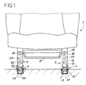
- each slide has, in cross section, the general shape of a "U"
- the two vertical wings 7a, 7b are vertical and are provided with their upper ends, on the one hand, of an internal return respectively 8a, 8b, on the other hand, of an external return 9a, 9b, and moreover, of a flat face upper 10a, 10b, forming a raceway, but can also form sliding path.
- Figures 2 to 4 show that each of the flanges has, in side view, the general shape of a stick, i.e. has a point 3a, 4a facing forwards, and a tip 3b, 4b facing backwards, separated by a concave central part and comprises, in each of its points, a respectively front 12 and rear 13 bore for, respectively, an axis of connection with the seat structure, and the joint 11 of the back structure 14.
- Each flange is in the form of a box open inwards. The opening of that 3 is closed by a closing plate 15 comprising stiffening ribs. This sheet is linked to the flange 3 by means of dismountable connection, such as screws, materialized by dashed lines 16 (FIG. 2).
- lever 26 receives the support of a radial lug 28, wedged on a pin 29 of a control bar 30 extending under the seat 2.
- This pin is freely mounted in rotation in the bore 32 of the flange, visible in FIG. 5.
- the flange 3 carries two bearings, respectively before 33 and rear 34 receiving, as shown in Figure 2, an axis respectively 35 and 36 the end of which forms a guide surface for a roller, respectively 37, 38.
- These two rollers come to bear on the raceways of the slide corresponding, namely on the raceway 10a for the roller 38, and on the raceway 10b of the same slide for the roller 37.
- the positioning means in the take-up flange 4 the positioning means, the means of guide in longitudinal translation and the locking means are worn by two carriages, respectively, front 40 and rear 41.
- the carriage posterior 41 comprises a body 42 having, in cross section, the general shape of a "U" whose core 42a is traversed longitudinally by cylindrical bores, 43 and 44 respectively, transversely by two cylindrical bores 45 and vertically by two through housings 46, 47.
- the two wings 42b are each traversed by a transverse bore 48 and each have an internal longitudinal groove 49 facing towards the groove of the other wing.
- the housing 46 contains a lock 120, identical to the lock 20 of the flange 3. This lock is articulated around an axis 50 (FIG. 11), disposed in the longitudinal bore 44.
- each of these hooks is intended to enter one of the notches 53 provided, as shown Figure 2, in each of the wings 7a, 7b of the corresponding slide.
- These hooks are associated with an upper step 54, forming a retaining bolt. This bolt is suitable, in the event of an impact, to come to bear under the internal return corresponding 8a or 8b of the slide to retain the base and the seat.
- the lock 120 is secured to a finger radial 55, projecting upwards.
- the housing 47 of the carriage body 42 contains a hook retainer 122, identical in shape to the hook 22 of the guide flange 3. As shown in Figure 13, this hook is articulated on an axis 56, arranged in the bore 43 of the body. At its lower part, it has a step 57 forming hook and fit, like the redan 54 of the lock, to come below the return internal 8a, 8b of the corresponding slide. At its upper part, it is provided a radial finger 58, projecting upwards.
- the bores 45 of the body are intended to receive two transverse axes 59 serving as pivots for two castors 60.
- each axis 59 rotates the corresponding wheel 60 by a cylindrical surface 62 which is offset by a value e with respect to its geometric axis.
- the axis 59 is equipped with a flat 63 making it possible to identify the angular position of this axis, therefore of the eccentric bearing, and consequently, to adjust the position of the axis of rotation of the caster in relation to the carriage.
- the slot 59a, formed in the head 59b of the axis, also participates in locating the adjustment position of the caster.
- the axis 59 is locked in position, for example, by a nut 64.
- the bores 48 formed in the wings 42b of the carriage body serve as housings for bearings 66 for a through axis 65.
- the ends of this axis 65 are carried by bores 67 provided, one in the lower part of the flange 4 and the other in a cheek 68 arranged parallel to the flange and connected to it by a wall 69.
- the flange, the cheek and the wall form an inverted “U” cap containing the carriages.
- FIG. 12 clearly shows that the interval I between the flange 4 and its wall 68 is greater than the width L of the carriage 41, so that provided, on each side of the carriage, Ja, Jb games, allowing it to move transversely, giving it its floating character.
- a blade spring folded into a “V” 71 is linked by its branch 71a to the cheek 68 and takes support, by its branch 71b, on the carriage 41 to return it to a position substantially median, facilitating its engagement in the slide in the seat installation phase.
- the carriage 41 is equipped with a positioning means which, in the embodiment shown, is constituted by a cap made of material plastic 70, forming a kind of protective casing for the pivoting elements of the carriage which pass through it through suitable openings, but it is evident that these positioning means can have any other shape and, by example, be constituted by a plastic plate having the same cross section as the cap, but attached to the carriage.
- a positioning means which, in the embodiment shown, is constituted by a cap made of material plastic 70, forming a kind of protective casing for the pivoting elements of the carriage which pass through it through suitable openings, but it is evident that these positioning means can have any other shape and, by example, be constituted by a plastic plate having the same cross section as the cap, but attached to the carriage.
- the carriage 40 comprises a body 142 having the same cross section as the body 42 of the carriage 41 and whose core 142a is crossed by two longitudinal bores 143, 144 and by a housing vertical through 147 for a retaining hook 122.
- the core 142a is also crossed by a transverse bore for an axis 59 receiving a caster 60.
- the two wings 142b of the body are crossed by transverse bores aligned two by two and each receiving a bearing 66.
- in these bearings are mounted two axes transverse 73. Each axis is arranged, by its ends, in bores 74 formed in the flange 4 and in his cheek 68. These two axes form slides on which the carriage 40 can slide transversely to adapt to the differences in transverse position of the slide relative to the seat or vice versa.
- a spring leaf 75 ensures the same function as the blade 71 of the other carriage 41.
- This carriage 40 also has longitudinal grooves 149, made in its wings and facing each other.
- the latch 120 and the retaining fingers 122 of the take-up flange 4 have a pivot which is controlled by a slide 123, arranged above of them.
- this slide has, in its core, a light 76 and two lights 77.
- the slide is provided at its ends with rollers 78 circulating in the grooves 49 and 149 formed in the wings of the two carriages 40, 41.
- the lights 76, 77 are crossed, each by one of the fingers 55, 58, respectively of the latch and retaining hooks, as shown in Figures 8, 11 and 13.
- the edges of these lights form ramps which, when moving the slide, can come into contact with the corresponding finger, to move it transversely and cause the bolt or hook to pivot corresponding.
- Figure 7 shows that the light 76 for the latch 120 is inclined transversely over its entire length, relative to the axis longitudinal of the slide 123 and has substantially straight edges, while the lights 77 for the hooks 122 are each composed of a longitudinal section 77a and an inclined section 77b.
- Each section longitudinal 77a has a length at least equal to the displacement stroke longitudinal that the slide 123 must perform to bring the lock of its locking position to its unlocking position.
- the slide is secured to a finger hook 81 projecting upwards and on which one of the ends of a tension spring 79, hooked by its other end to a fixed point of the flange and, for example, to an axis 73, as shown in FIG. 8.
- the slide 123 is equipped with a heel 80, able to cooperate with a wedging bar 82 forming part of a feeler presence of the slide.
- this probe consists of a bent lever 83, pivotally mounted on a transverse axis 84 swirling in the flange 4 and its cheek 68.
- This lever carries the bar 82, at the end of its branch substantially horizontal, while the end of its substantially vertical branch is fitted with a caster 85.
- the slide is returned by the spring 79 until the heel 80 abuts on the bar 82, thus ensuring immobilization in the position of extraction of the lock 120 and hooks 122.
- This facilitates the extraction of the seat relative to the slide and subsequently the replacement of the latches and hooks in the slide, while avoiding forming, on the base of the seat, protrusions that can catch other elements.
- FIG. 5 shows that the slide 23 of the guide flange 3 is sliding mounted on cylindrical slides 86 and 87 extending between transverse wings 3c of the flange, and that the return of the slide is ensured by the spring 24 which is arranged around the slide 87.
- the slide comprises also lights 76, 77 which control the tilting of the lock 20 and retaining hooks 22 cooperating with the fingers of these elements.
- the locking means of the slide 23, in its position holding the latch 20 and the hooks 22 in the extraction position, are produced differently, as shown in more detail in Figure 15.
- the means of probing, coming into contact with the slide when the seat is brought to these consist of a piston 88, slidably mounted in a bore vertical shouldered 89, formed in a protrusion 90 of the flange 3.
- the rod 88a of the piston 88 is linked, for example by a transverse pin 92, to a transverse finger 93 extending above the path of the slide 23.
- a spring 91 interposed between the piston 88 and the bottom of the housing 89, urges permanently this piston down, so that its finger 93 comes in support on the edge of the slide 23.
- This edge is locally equipped with a notch 94, visible in FIG. 5, which receives the finger 93 when the slide is moved to control the setting in position of release and extraction of the lock 20 and retaining hooks 22.
- the contact of the end of the piston 88 with the path of rolling of the slide causes the piston 88 to retract into its housing 89 and the release of his finger 93 from the notch 94, that is to say allows the return spring 24 to cause the displacement of the slide for automatically bring the latch 20 and the retaining hooks 22 in position, respectively of locking and vertical restraint of the base from the headquarters.
- the end of the piston 88 is provided with a roller 95 to prevent the adjustment movements of the base on the slide are braked by the contact of this piston with the slide and the slide is scratched by this piston.
- the guide flange 3 cooperates with its slide to provide translational guidance for this movement, while that the floating carriages 40 and 41 of the take-up flange 4 absorb, by their transverse displacement, the variation in distance between the two slides and that, simultaneously, the pivoting carriage 41 absorbs, by its pivoting, the level variations of the upper face of the slide on which it rolls.
- rollers 37, 38 and 60 are chosen from a series of rollers having the same bore diameter, but having outside diameters increasing in increments of value at most equal to that of the eccentricity e of the eccentric bearing.
- the rollers 37, 38 and 60 having a nominal diameter of 26 millimeters , are chosen from rollers with diameters of 23, 26 and 29 millimeters.
- the flange of retrofit carries a single carriage, similar to carriage 40, but longer, and linked to the flange by a single axis of articulation.
- the front and rear ends of the flange rest on those of the carriage with interposition of means dampers of the pivoting movement, these means being associated with stops limiting the pivoting stroke.
Landscapes
- Engineering & Computer Science (AREA)
- Aviation & Aerospace Engineering (AREA)
- Transportation (AREA)
- Mechanical Engineering (AREA)
- Seats For Vehicles (AREA)
- Chairs For Special Purposes, Such As Reclining Chairs (AREA)
Applications Claiming Priority (2)
| Application Number | Priority Date | Filing Date | Title |
|---|---|---|---|
| FR0010228A FR2812251B1 (fr) | 2000-07-27 | 2000-07-27 | Dispositif de guidage et d'ancrage pour siege amovible de vehicule |
| FR0010228 | 2000-07-27 |
Publications (2)
| Publication Number | Publication Date |
|---|---|
| EP1176047A1 true EP1176047A1 (de) | 2002-01-30 |
| EP1176047B1 EP1176047B1 (de) | 2002-11-27 |
Family
ID=8853251
Family Applications (1)
| Application Number | Title | Priority Date | Filing Date |
|---|---|---|---|
| EP20010420158 Expired - Lifetime EP1176047B1 (de) | 2000-07-27 | 2001-07-12 | Vorrichtung zum Führen und Verankern herausnehmbarer Fahrzeugsitze |
Country Status (5)
| Country | Link |
|---|---|
| EP (1) | EP1176047B1 (de) |
| DE (1) | DE60100054T2 (de) |
| ES (1) | ES2187493T3 (de) |
| FR (1) | FR2812251B1 (de) |
| PT (1) | PT1176047E (de) |
Cited By (39)
| Publication number | Priority date | Publication date | Assignee | Title |
|---|---|---|---|---|
| FR2835790A1 (fr) * | 2002-02-08 | 2003-08-15 | Antolin Grupo Ing Sa | Dispositif de calage vertical et automatique d'un siege de vehicule |
| EP1407920A3 (de) * | 2002-10-09 | 2005-03-23 | Koller Engineering Limited | Verankerungssystem |
| WO2006017633A1 (en) | 2004-08-05 | 2006-02-16 | Johnson Controls Technology Company | Sliding latch system |
| DE102009039349A1 (de) | 2009-08-29 | 2010-03-25 | Daimler Ag | Sitzverriegelungsvorrichtung |
| EP2298590A1 (de) | 2009-09-21 | 2011-03-23 | Grupo Antolin-Ingenieria, S.A. | Verankerungsvorrichtung für herausnehmbaren Sitz eines Kraftfahrzeugs |
| DE102009042597A1 (de) * | 2009-09-23 | 2011-03-24 | Hydac Accessories Gmbh | Arretierungsssystem |
| WO2012025539A1 (de) * | 2010-08-23 | 2012-03-01 | Johnson Controls Gmbh | Längsverstellvorrichtung für einen fahrzeugsitz mit trennbarer ober- und unterschiene |
| CN103241146A (zh) * | 2012-02-10 | 2013-08-14 | 格鲁坡安托林-英杰尼瑞亚股份有限公司 | 用于可拆除座椅的锚固机构 |
| EP3162614A1 (de) | 2015-10-27 | 2017-05-03 | Grupo Antolin-Ingenieria, S.A. | Sitz für fahrzeug, der einen begrenzungsmechanismus für das verschieben hat |
| WO2019174720A1 (en) * | 2018-03-13 | 2019-09-19 | Pressan Madeni Esya San. Tic. A.S. | Vehicle seat mounting arrangement |
| FR3080804A1 (fr) * | 2018-05-04 | 2019-11-08 | Lear Corporation | Module d'ancrage |
| CN110435492A (zh) * | 2018-05-04 | 2019-11-12 | 李尔公司 | 支撑组件 |
| US10562414B2 (en) | 2018-05-04 | 2020-02-18 | Lear Corporation | Track assembly |
| US20200086997A1 (en) * | 2018-09-18 | 2020-03-19 | Rockwell Collins, Inc. | Dynamic Retention System for an Aircraft Seat |
| WO2020151787A1 (de) * | 2019-01-22 | 2020-07-30 | Grammer Ag | Führungsvorrichtung mit verriegelungsvorrichtung |
| US10855037B2 (en) | 2018-12-17 | 2020-12-01 | Lear Corporation | Support assembly with a support member and a track assembly |
| US10882420B2 (en) | 2019-03-08 | 2021-01-05 | Lear Corporation | Track assembly |
| US10906431B2 (en) | 2018-05-04 | 2021-02-02 | Lear Corporation | Track assembly |
| US10926667B2 (en) | 2018-05-04 | 2021-02-23 | Lear Corporation | Track assembly |
| US10950977B2 (en) | 2018-12-18 | 2021-03-16 | Lear Corporation | Track assembly for a vehicle component |
| US11007905B2 (en) * | 2018-07-04 | 2021-05-18 | Magna Seating (Germany) Gmbh | Blocking and contact system for the electrical connection of an on-board power supply of a motor vehicle to a removable vehicle seat or a seat system |
| US11040653B2 (en) | 2019-02-25 | 2021-06-22 | Lear Corporation | Track assembly |
| US11040639B2 (en) | 2018-05-04 | 2021-06-22 | Lear Corporation | Track assembly |
| US11040638B2 (en) | 2018-05-04 | 2021-06-22 | Lear Corporation | Track assembly |
| US11117538B2 (en) | 2018-12-17 | 2021-09-14 | Lear Corporation | Electrical assembly |
| US11225201B2 (en) | 2018-12-10 | 2022-01-18 | Lear Corporation | Track assembly |
| US11299075B2 (en) | 2019-03-06 | 2022-04-12 | Lear Corporation | Electrical assembly |
| US11323114B2 (en) | 2019-10-04 | 2022-05-03 | Lear Corporation | Electrical system |
| US11358497B2 (en) | 2018-05-04 | 2022-06-14 | Lear Corporation | Track system having a rolling member |
| US11440482B2 (en) | 2018-12-10 | 2022-09-13 | Lear Corporation | Track assembly |
| US11463083B2 (en) | 2019-10-04 | 2022-10-04 | Lear Corporation | Electrical system |
| US11505141B2 (en) | 2020-10-23 | 2022-11-22 | Lear Corporation | Electrical system with track assembly and support assembly |
| US11506272B2 (en) | 2020-02-21 | 2022-11-22 | Lear Corporation | Track system with a support member |
| US11613220B2 (en) | 2018-12-17 | 2023-03-28 | Lear Corporation | Electrical assembly |
| US11634101B2 (en) | 2019-10-04 | 2023-04-25 | Lear Corporation | Removable component system |
| US11708011B2 (en) | 2021-03-05 | 2023-07-25 | Camaco, Llc. | Reinforced track assembly for vehicle seat |
| US11807142B2 (en) | 2019-03-06 | 2023-11-07 | Lear Corporation | Electrical track assembly |
| US11975665B2 (en) | 2019-02-20 | 2024-05-07 | Lear Corporation | Electrical assembly |
| US12253156B2 (en) | 2020-02-21 | 2025-03-18 | Lear Corporation | Track system with a support member |
Families Citing this family (10)
| Publication number | Priority date | Publication date | Assignee | Title |
|---|---|---|---|---|
| FR2837149B1 (fr) | 2002-03-15 | 2004-06-25 | Antolin Grupo Ing Sa | Compensateur de defaut de parallelisme pour siege amovible de vehicule |
| DE102004025506B4 (de) * | 2004-05-21 | 2010-04-08 | Johnson Controls Gmbh | Steuerungsvorrichtung für einen Fahrzeugsitz |
| DE102004035480B4 (de) | 2004-07-14 | 2018-03-01 | Volkswagen Ag | Schienenanordnung |
| DE102005043552A1 (de) * | 2005-09-12 | 2007-03-15 | GM Global Technology Operations, Inc., Detroit | Kraftfahrzeug mit einem Sitz |
| DE102008039621A1 (de) * | 2008-08-25 | 2010-03-04 | GM Global Technology Operations, Inc., Detroit | Sitzbefestigung |
| DE102009038126B4 (de) * | 2009-08-11 | 2018-12-13 | Adient Luxembourg Holding S.À R.L. | Längseinsteller für einen Fahrzeugsitz |
| DE102010021662A1 (de) | 2010-05-26 | 2011-12-01 | Daimler Ag | Verstellvorrichtung, inbesondere für einen Fahrzeugsitz |
| US12233756B2 (en) | 2018-05-04 | 2025-02-25 | Lear Corporation | Track system with a support member |
| DE102019120194A1 (de) | 2019-07-25 | 2021-01-28 | Aguti Produktentwicklung & Design Gmbh | Vorrichtung zur Anbringung einer Sitzanordnung in einem Fahrzeug und Fahrzeug |
| DE102021104010B4 (de) | 2020-02-21 | 2024-01-11 | Lear Corporation | Schienensystem mit einem Stützelement und Anker für ein Stützelement eines Schienensystems |
Citations (4)
| Publication number | Priority date | Publication date | Assignee | Title |
|---|---|---|---|---|
| EP0925996A1 (de) * | 1997-12-22 | 1999-06-30 | Bertrand Faure Equipements S.A. | Fahrzeugsitzeinheit mit auf Gleitschienen montiertem, abnehmbarem Sitz |
| EP0947380A1 (de) * | 1998-03-30 | 1999-10-06 | Renault | Auf dem Schieneboden eingebaute Zahnstangenvorrichtung |
| EP0949111A1 (de) * | 1998-04-06 | 1999-10-13 | Renault | Modulares Befestigungssystem mit Nockensteuerung |
| EP0976605A1 (de) * | 1998-07-31 | 2000-02-02 | Grupo Antolin-Ingenieria S.A. | Kraftfahrzeugsitz, herausnehmbar, umwendbar und längsverstellbar durch Stelleinheiten auf dessen Gleitschienen |
-
2000
- 2000-07-27 FR FR0010228A patent/FR2812251B1/fr not_active Expired - Fee Related
-
2001
- 2001-07-12 ES ES01420158T patent/ES2187493T3/es not_active Expired - Lifetime
- 2001-07-12 DE DE2001600054 patent/DE60100054T2/de not_active Expired - Lifetime
- 2001-07-12 PT PT01420158T patent/PT1176047E/pt unknown
- 2001-07-12 EP EP20010420158 patent/EP1176047B1/de not_active Expired - Lifetime
Patent Citations (4)
| Publication number | Priority date | Publication date | Assignee | Title |
|---|---|---|---|---|
| EP0925996A1 (de) * | 1997-12-22 | 1999-06-30 | Bertrand Faure Equipements S.A. | Fahrzeugsitzeinheit mit auf Gleitschienen montiertem, abnehmbarem Sitz |
| EP0947380A1 (de) * | 1998-03-30 | 1999-10-06 | Renault | Auf dem Schieneboden eingebaute Zahnstangenvorrichtung |
| EP0949111A1 (de) * | 1998-04-06 | 1999-10-13 | Renault | Modulares Befestigungssystem mit Nockensteuerung |
| EP0976605A1 (de) * | 1998-07-31 | 2000-02-02 | Grupo Antolin-Ingenieria S.A. | Kraftfahrzeugsitz, herausnehmbar, umwendbar und längsverstellbar durch Stelleinheiten auf dessen Gleitschienen |
Cited By (70)
| Publication number | Priority date | Publication date | Assignee | Title |
|---|---|---|---|---|
| FR2835790A1 (fr) * | 2002-02-08 | 2003-08-15 | Antolin Grupo Ing Sa | Dispositif de calage vertical et automatique d'un siege de vehicule |
| US6736458B2 (en) | 2002-02-08 | 2004-05-18 | Grupo Antolin-Ingenieria, S.A. | Device for the vertical and automatic wedging of a vehicle seat |
| EP1334865A3 (de) * | 2002-02-08 | 2004-06-09 | Grupo Antolin-Ingenieria, S.A. | Automatisch Vertikalverkeilungseinrichtung eines Fahrzeugsitzes |
| EP1407920A3 (de) * | 2002-10-09 | 2005-03-23 | Koller Engineering Limited | Verankerungssystem |
| WO2006017633A1 (en) | 2004-08-05 | 2006-02-16 | Johnson Controls Technology Company | Sliding latch system |
| CN100528627C (zh) * | 2004-08-05 | 2009-08-19 | 约翰逊控制技术公司 | 滑动锁止系统 |
| US7819475B2 (en) | 2004-08-05 | 2010-10-26 | Johnson Controls Technology Company | Sliding latching system |
| US8109577B2 (en) | 2004-08-05 | 2012-02-07 | Johnson Controls Technology Company | Sliding latch system |
| DE102009039349A1 (de) | 2009-08-29 | 2010-03-25 | Daimler Ag | Sitzverriegelungsvorrichtung |
| EP2298590A1 (de) | 2009-09-21 | 2011-03-23 | Grupo Antolin-Ingenieria, S.A. | Verankerungsvorrichtung für herausnehmbaren Sitz eines Kraftfahrzeugs |
| FR2950292A1 (fr) * | 2009-09-21 | 2011-03-25 | Antolin Grupo Ing Sa | Dispositif d'ancrage de siege amovible de vehicule automobile |
| DE102009042597A1 (de) * | 2009-09-23 | 2011-03-24 | Hydac Accessories Gmbh | Arretierungsssystem |
| WO2012025539A1 (de) * | 2010-08-23 | 2012-03-01 | Johnson Controls Gmbh | Längsverstellvorrichtung für einen fahrzeugsitz mit trennbarer ober- und unterschiene |
| CN103068621A (zh) * | 2010-08-23 | 2013-04-24 | 约翰逊控股公司 | 包括可分离的上和下部轨道用于车辆座椅的纵向调整装置 |
| CN103068621B (zh) * | 2010-08-23 | 2016-05-11 | 约翰逊控股公司 | 包括可分离的上和下部轨道用于车辆座椅的纵向调整装置 |
| US9701217B2 (en) | 2010-08-23 | 2017-07-11 | Johnson Controls Gmbh | Longitudinal adjusting device for a vehicle seat, comprising a separable upper and lower rail |
| CN103241146A (zh) * | 2012-02-10 | 2013-08-14 | 格鲁坡安托林-英杰尼瑞亚股份有限公司 | 用于可拆除座椅的锚固机构 |
| FR2986751A1 (fr) * | 2012-02-10 | 2013-08-16 | Antolin Grupo Ing Sa | Mecanisme d'ancrage d'un siege amovible |
| CN103241146B (zh) * | 2012-02-10 | 2017-09-19 | 格鲁坡安托林-英杰尼瑞亚股份有限公司 | 用于可拆除座椅的锚固机构 |
| EP3162614A1 (de) | 2015-10-27 | 2017-05-03 | Grupo Antolin-Ingenieria, S.A. | Sitz für fahrzeug, der einen begrenzungsmechanismus für das verschieben hat |
| WO2019174720A1 (en) * | 2018-03-13 | 2019-09-19 | Pressan Madeni Esya San. Tic. A.S. | Vehicle seat mounting arrangement |
| CN112135750B (zh) * | 2018-03-13 | 2023-12-12 | 普善金属制品工业与贸易公司 | 车辆座椅安装组件 |
| US20210016685A1 (en) * | 2018-03-13 | 2021-01-21 | Pressan Madeni Esya San. Tic. A.S. | Vehicle seat mounting arrangement |
| CN112135750A (zh) * | 2018-03-13 | 2020-12-25 | 普善金属制品工业与贸易公司 | 车辆座椅安装组件 |
| US10889208B2 (en) | 2018-05-04 | 2021-01-12 | Lear Corporation | Track assembly |
| US10926667B2 (en) | 2018-05-04 | 2021-02-23 | Lear Corporation | Track assembly |
| US11358497B2 (en) | 2018-05-04 | 2022-06-14 | Lear Corporation | Track system having a rolling member |
| US10759308B2 (en) | 2018-05-04 | 2020-09-01 | Lear Corporation | Support assembly |
| FR3080804A1 (fr) * | 2018-05-04 | 2019-11-08 | Lear Corporation | Module d'ancrage |
| US10850645B2 (en) | 2018-05-04 | 2020-12-01 | Lear Corporation | Track assembly |
| US10850644B2 (en) | 2018-05-04 | 2020-12-01 | Lear Corporation | Support assembly with cam assembly |
| US11040638B2 (en) | 2018-05-04 | 2021-06-22 | Lear Corporation | Track assembly |
| US11040639B2 (en) | 2018-05-04 | 2021-06-22 | Lear Corporation | Track assembly |
| US10562414B2 (en) | 2018-05-04 | 2020-02-18 | Lear Corporation | Track assembly |
| CN110435492A (zh) * | 2018-05-04 | 2019-11-12 | 李尔公司 | 支撑组件 |
| US10906431B2 (en) | 2018-05-04 | 2021-02-02 | Lear Corporation | Track assembly |
| US11007905B2 (en) * | 2018-07-04 | 2021-05-18 | Magna Seating (Germany) Gmbh | Blocking and contact system for the electrical connection of an on-board power supply of a motor vehicle to a removable vehicle seat or a seat system |
| US20200086997A1 (en) * | 2018-09-18 | 2020-03-19 | Rockwell Collins, Inc. | Dynamic Retention System for an Aircraft Seat |
| US10906650B2 (en) | 2018-09-18 | 2021-02-02 | Rockwell Collins, Inc. | Dynamic retention system for an aircraft seat |
| EP3626618A1 (de) * | 2018-09-18 | 2020-03-25 | Rockwell Collins, Inc. | Dynamisches rückhaltesystem für einen flugzeugsitz |
| US11440482B2 (en) | 2018-12-10 | 2022-09-13 | Lear Corporation | Track assembly |
| US11225201B2 (en) | 2018-12-10 | 2022-01-18 | Lear Corporation | Track assembly |
| US10855037B2 (en) | 2018-12-17 | 2020-12-01 | Lear Corporation | Support assembly with a support member and a track assembly |
| US11613220B2 (en) | 2018-12-17 | 2023-03-28 | Lear Corporation | Electrical assembly |
| US11117538B2 (en) | 2018-12-17 | 2021-09-14 | Lear Corporation | Electrical assembly |
| US10950977B2 (en) | 2018-12-18 | 2021-03-16 | Lear Corporation | Track assembly for a vehicle component |
| DE102019000381B4 (de) | 2019-01-22 | 2023-04-27 | Volkswagen Aktiengesellschaft | Führungsvorrichtung mit Verriegelungsvorrichtung |
| CN113474212A (zh) * | 2019-01-22 | 2021-10-01 | 大众汽车股份公司 | 具有锁定装置的导引装置 |
| WO2020151787A1 (de) * | 2019-01-22 | 2020-07-30 | Grammer Ag | Führungsvorrichtung mit verriegelungsvorrichtung |
| US12049158B2 (en) | 2019-01-22 | 2024-07-30 | Volkswagen Aktiengesellschaft | Guide device with locking device |
| US11975665B2 (en) | 2019-02-20 | 2024-05-07 | Lear Corporation | Electrical assembly |
| US11040653B2 (en) | 2019-02-25 | 2021-06-22 | Lear Corporation | Track assembly |
| US11299075B2 (en) | 2019-03-06 | 2022-04-12 | Lear Corporation | Electrical assembly |
| US12401174B2 (en) | 2019-03-06 | 2025-08-26 | Lear Corporation | Electrical track assembly |
| US11807142B2 (en) | 2019-03-06 | 2023-11-07 | Lear Corporation | Electrical track assembly |
| US10882420B2 (en) | 2019-03-08 | 2021-01-05 | Lear Corporation | Track assembly |
| US11323114B2 (en) | 2019-10-04 | 2022-05-03 | Lear Corporation | Electrical system |
| US11634101B2 (en) | 2019-10-04 | 2023-04-25 | Lear Corporation | Removable component system |
| US11463083B2 (en) | 2019-10-04 | 2022-10-04 | Lear Corporation | Electrical system |
| US12044301B2 (en) | 2020-02-21 | 2024-07-23 | Lear Corporation | Track system with a support member |
| US11906028B2 (en) | 2020-02-21 | 2024-02-20 | Lear Corporation | Track system with a support member |
| US11506272B2 (en) | 2020-02-21 | 2022-11-22 | Lear Corporation | Track system with a support member |
| US12055205B2 (en) | 2020-02-21 | 2024-08-06 | Lear Corporation | Track system with a support member |
| US12181033B2 (en) | 2020-02-21 | 2024-12-31 | Lear Corporation | Track system with a support member |
| US12253156B2 (en) | 2020-02-21 | 2025-03-18 | Lear Corporation | Track system with a support member |
| US11835119B2 (en) | 2020-02-21 | 2023-12-05 | Lear Corporation | Track system with a support member |
| US12012056B2 (en) | 2020-10-23 | 2024-06-18 | Lear Corporation | Electrical system with track assembly and support assembly |
| US11505141B2 (en) | 2020-10-23 | 2022-11-22 | Lear Corporation | Electrical system with track assembly and support assembly |
| US11708011B2 (en) | 2021-03-05 | 2023-07-25 | Camaco, Llc. | Reinforced track assembly for vehicle seat |
| US12263762B2 (en) | 2021-03-05 | 2025-04-01 | Camaco, LLC | Reinforced track assembly for vehicle seat |
Also Published As
| Publication number | Publication date |
|---|---|
| FR2812251B1 (fr) | 2003-01-03 |
| DE60100054D1 (de) | 2003-01-09 |
| PT1176047E (pt) | 2003-04-30 |
| EP1176047B1 (de) | 2002-11-27 |
| FR2812251A1 (fr) | 2002-02-01 |
| DE60100054T2 (de) | 2003-07-17 |
| ES2187493T3 (es) | 2003-06-16 |
Similar Documents
| Publication | Publication Date | Title |
|---|---|---|
| EP1176047B1 (de) | Vorrichtung zum Führen und Verankern herausnehmbarer Fahrzeugsitze | |
| EP0945301B1 (de) | Gleitschiene für Fahrzeugsitz und mit solcher Schiene ausgerüsteter Sitz | |
| EP0615879B1 (de) | Lageeinstellungsvorrichtung für Kraftfahrzeugsitze | |
| EP0931689B1 (de) | Kraftfahrzeugsitz, herausnehmbar, umwendbar und längsverstellbar | |
| EP0976605B1 (de) | Kraftfahrzeugsitz, herausnehmbar, umwendbar und längsverstellbar durch Stelleinheiten auf dessen Gleitschienen | |
| CA2460630C (fr) | Glissiere pour siege de vehicule automobile | |
| FR2851211A1 (fr) | Siege rabattable et vehicule comportant un tel siege | |
| EP1699661A2 (de) | Halterung zur befestigung eines sitzes an einem kraftfahrzeugboden mittels einziehbarer führungsblöcke | |
| WO2008084156A2 (fr) | Glissiere et siege muni d'un systeme de verrouillage | |
| EP0947380B1 (de) | Auf dem Schienenboden eingebaute Zahnstangenvorrichtung | |
| CA2080145C (fr) | Glissiere pour siege de vehicule a position de retour fixe | |
| FR2853597A1 (fr) | Glissiere pour siege de vehicule automobile | |
| FR3116771A1 (fr) | Siège de véhicule à assise et dossiers inclinables pour faciliter l’accès aux places arrière | |
| EP1016359B1 (de) | Faltbarer Tischtennistisch mit Verriegelungsmitteln | |
| EP0800952A1 (de) | Kraftfahrzeugsitz, nach vorn bewegbar, um zu einem Hinterraum Zugang zu haben | |
| FR2882538A1 (fr) | Glissiere pour siege de vehicule et siege comportant une telle glissiere | |
| EP4269220B1 (de) | Parkvorrichtung für einen fahrrad | |
| WO2017046527A1 (fr) | Dispositif de verrouillage bi-positions d'un dossier de siege arriere de vehicule automobile | |
| FR2897092A1 (fr) | Dispositif de guidage d'une porte laterale coulissante et porte coulissante comportant un tel dispositif de guidage. | |
| FR2892349A1 (fr) | Siege de vehicule automobile et vehicule automobile muni d'un tel siege | |
| FR2816556A1 (fr) | Mecanisme d'articulation pour siege ou banquette arriere reglable longitudinalement, notamment pour vehicule automobile | |
| FR2881383A1 (fr) | Unite de dossier d'un siege de vehicule automobile | |
| FR3115244A1 (fr) | Glissière pour siège de véhicule et siège de véhicule comportant une telle glissière. | |
| FR2829440A1 (fr) | Siege de vehicule et ensemble d'assise comportant un tel siege | |
| FR2862258A1 (fr) | Mecanisme de commande pour siege automobile, siege muni d'un tel mecanisme et vehicule muni d'un tel siege |
Legal Events
| Date | Code | Title | Description |
|---|---|---|---|
| PUAI | Public reference made under article 153(3) epc to a published international application that has entered the european phase |
Free format text: ORIGINAL CODE: 0009012 |
|
| 17P | Request for examination filed |
Effective date: 20010720 |
|
| AK | Designated contracting states |
Kind code of ref document: A1 Designated state(s): AT BE CH CY DE DK ES FI FR GB GR IE IT LI LU MC NL PT SE TR Kind code of ref document: A1 Designated state(s): DE ES FR GB IT PT |
|
| AX | Request for extension of the european patent |
Free format text: AL;LT;LV;MK;RO;SI |
|
| GRAG | Despatch of communication of intention to grant |
Free format text: ORIGINAL CODE: EPIDOS AGRA |
|
| GRAG | Despatch of communication of intention to grant |
Free format text: ORIGINAL CODE: EPIDOS AGRA |
|
| GRAH | Despatch of communication of intention to grant a patent |
Free format text: ORIGINAL CODE: EPIDOS IGRA |
|
| 17Q | First examination report despatched |
Effective date: 20020606 |
|
| GRAH | Despatch of communication of intention to grant a patent |
Free format text: ORIGINAL CODE: EPIDOS IGRA |
|
| GRAA | (expected) grant |
Free format text: ORIGINAL CODE: 0009210 |
|
| AKX | Designation fees paid |
Free format text: DE ES FR GB IT PT |
|
| AK | Designated contracting states |
Kind code of ref document: B1 Designated state(s): DE ES FR GB IT PT |
|
| REG | Reference to a national code |
Ref country code: GB Ref legal event code: FG4D Free format text: NOT ENGLISH |
|
| GBT | Gb: translation of ep patent filed (gb section 77(6)(a)/1977) |
Effective date: 20021127 |
|
| REG | Reference to a national code |
Ref country code: IE Ref legal event code: FG4D Free format text: FRENCH |
|
| REF | Corresponds to: |
Ref document number: 60100054 Country of ref document: DE Date of ref document: 20030109 |
|
| REG | Reference to a national code |
Ref country code: PT Ref legal event code: SC4A Free format text: AVAILABILITY OF NATIONAL TRANSLATION Effective date: 20030226 |
|
| REG | Reference to a national code |
Ref country code: ES Ref legal event code: FG2A Ref document number: 2187493 Country of ref document: ES Kind code of ref document: T3 |
|
| REG | Reference to a national code |
Ref country code: IE Ref legal event code: FD4D Ref document number: 1176047E Country of ref document: IE |
|
| PLBE | No opposition filed within time limit |
Free format text: ORIGINAL CODE: 0009261 |
|
| STAA | Information on the status of an ep patent application or granted ep patent |
Free format text: STATUS: NO OPPOSITION FILED WITHIN TIME LIMIT |
|
| 26N | No opposition filed |
Effective date: 20030828 |
|
| PGFP | Annual fee paid to national office [announced via postgrant information from national office to epo] |
Ref country code: PT Payment date: 20110621 Year of fee payment: 11 |
|
| PGFP | Annual fee paid to national office [announced via postgrant information from national office to epo] |
Ref country code: GB Payment date: 20110516 Year of fee payment: 11 |
|
| PGFP | Annual fee paid to national office [announced via postgrant information from national office to epo] |
Ref country code: ES Payment date: 20110726 Year of fee payment: 11 |
|
| PGFP | Annual fee paid to national office [announced via postgrant information from national office to epo] |
Ref country code: IT Payment date: 20110721 Year of fee payment: 11 |
|
| REG | Reference to a national code |
Ref country code: PT Ref legal event code: MM4A Free format text: LAPSE DUE TO NON-PAYMENT OF FEES Effective date: 20130114 |
|
| GBPC | Gb: european patent ceased through non-payment of renewal fee |
Effective date: 20120712 |
|
| PG25 | Lapsed in a contracting state [announced via postgrant information from national office to epo] |
Ref country code: GB Free format text: LAPSE BECAUSE OF NON-PAYMENT OF DUE FEES Effective date: 20120712 |
|
| PG25 | Lapsed in a contracting state [announced via postgrant information from national office to epo] |
Ref country code: PT Free format text: LAPSE BECAUSE OF NON-PAYMENT OF DUE FEES Effective date: 20130114 Ref country code: IT Free format text: LAPSE BECAUSE OF NON-PAYMENT OF DUE FEES Effective date: 20120712 |
|
| REG | Reference to a national code |
Ref country code: ES Ref legal event code: FD2A Effective date: 20131021 |
|
| PG25 | Lapsed in a contracting state [announced via postgrant information from national office to epo] |
Ref country code: ES Free format text: LAPSE BECAUSE OF NON-PAYMENT OF DUE FEES Effective date: 20120713 |
|
| REG | Reference to a national code |
Ref country code: FR Ref legal event code: PLFP Year of fee payment: 16 |
|
| REG | Reference to a national code |
Ref country code: FR Ref legal event code: PLFP Year of fee payment: 17 |
|
| REG | Reference to a national code |
Ref country code: DE Ref legal event code: R082 Ref document number: 60100054 Country of ref document: DE Representative=s name: WEICKMANN & WEICKMANN PATENTANWAELTE - RECHTSA, DE Ref country code: DE Ref legal event code: R081 Ref document number: 60100054 Country of ref document: DE Owner name: LEAR CORPORATION (N.D.GES.D. STAATES DELAWARE), US Free format text: FORMER OWNER: GRUPO ANTOLIN-INGENIERIA S.A., BURGOS, ES Ref country code: DE Ref legal event code: R082 Ref document number: 60100054 Country of ref document: DE Representative=s name: WEICKMANN & WEICKMANN PATENT- UND RECHTSANWAEL, DE |
|
| REG | Reference to a national code |
Ref country code: FR Ref legal event code: TP Owner name: LEAR CORPORATION, US Effective date: 20171127 |
|
| REG | Reference to a national code |
Ref country code: FR Ref legal event code: PLFP Year of fee payment: 18 |
|
| PGFP | Annual fee paid to national office [announced via postgrant information from national office to epo] |
Ref country code: DE Payment date: 20190729 Year of fee payment: 19 Ref country code: FR Payment date: 20190725 Year of fee payment: 19 |
|
| REG | Reference to a national code |
Ref country code: DE Ref legal event code: R119 Ref document number: 60100054 Country of ref document: DE |
|
| PG25 | Lapsed in a contracting state [announced via postgrant information from national office to epo] |
Ref country code: FR Free format text: LAPSE BECAUSE OF NON-PAYMENT OF DUE FEES Effective date: 20200731 |
|
| PG25 | Lapsed in a contracting state [announced via postgrant information from national office to epo] |
Ref country code: DE Free format text: LAPSE BECAUSE OF NON-PAYMENT OF DUE FEES Effective date: 20210202 |