EP1176263A2 - Heat insulating building element - Google Patents
Heat insulating building element Download PDFInfo
- Publication number
- EP1176263A2 EP1176263A2 EP01115445A EP01115445A EP1176263A2 EP 1176263 A2 EP1176263 A2 EP 1176263A2 EP 01115445 A EP01115445 A EP 01115445A EP 01115445 A EP01115445 A EP 01115445A EP 1176263 A2 EP1176263 A2 EP 1176263A2
- Authority
- EP
- European Patent Office
- Prior art keywords
- component
- thermal insulation
- rail
- recesses
- insulation according
- Prior art date
- Legal status (The legal status is an assumption and is not a legal conclusion. Google has not performed a legal analysis and makes no representation as to the accuracy of the status listed.)
- Granted
Links
- 230000003014 reinforcing effect Effects 0.000 claims abstract description 32
- 238000009413 insulation Methods 0.000 claims abstract description 25
- 230000002787 reinforcement Effects 0.000 claims description 18
- 239000000463 material Substances 0.000 claims description 10
- 239000006260 foam Substances 0.000 claims description 3
- 239000011810 insulating material Substances 0.000 claims description 2
- 239000012858 resilient material Substances 0.000 claims 2
- 239000000853 adhesive Substances 0.000 claims 1
- 230000001070 adhesive effect Effects 0.000 claims 1
- 238000006073 displacement reaction Methods 0.000 abstract 1
- 238000003780 insertion Methods 0.000 description 3
- 230000037431 insertion Effects 0.000 description 3
- 229910000746 Structural steel Inorganic materials 0.000 description 1
- 238000010276 construction Methods 0.000 description 1
- 230000006866 deterioration Effects 0.000 description 1
- 239000003063 flame retardant Substances 0.000 description 1
- 230000001771 impaired effect Effects 0.000 description 1
- 238000009434 installation Methods 0.000 description 1
- 239000012774 insulation material Substances 0.000 description 1
- 239000012212 insulator Substances 0.000 description 1
- 230000002093 peripheral effect Effects 0.000 description 1
- 238000003466 welding Methods 0.000 description 1
Images

Classifications
-
- E—FIXED CONSTRUCTIONS
- E04—BUILDING
- E04B—GENERAL BUILDING CONSTRUCTIONS; WALLS, e.g. PARTITIONS; ROOFS; FLOORS; CEILINGS; INSULATION OR OTHER PROTECTION OF BUILDINGS
- E04B1/00—Constructions in general; Structures which are not restricted either to walls, e.g. partitions, or floors or ceilings or roofs
- E04B1/003—Balconies; Decks
- E04B1/0038—Anchoring devices specially adapted therefor with means for preventing cold bridging
Definitions
- the invention relates to a component for thermal insulation between two components, especially between a building and a projecting outer part, the component being arranged in a joint between the two components Insulating body with integrated reinforcing bars, which extends across extend to the insulating body through this, and from at least one Rail made of harder material than the insulating body that is on or near their two the sides facing the components have recesses for the reinforcing bars, the rail in the area between the two recesses for a rebar a counter bearing for the rebar Has a head start.
- Such a component for thermal insulation is for example from DE-U 298 07 381 known.
- the rail mentioned here serves the reinforcing bars, in particular to fix the tension rods in the relatively soft insulating body material. This makes it possible to ensure that the reinforcing bars are intended for them Have course, so for example the tie rods perpendicular to the longitudinal extent of the insulating body run in the horizontal plane.
- the length of a component for thermal insulation is usually one Meters and accordingly has a variety of reinforcing bars and in particular tension rods set by the bar; now becomes such a component transported to the installation position on the construction site, this is done in the Usually by carrying and attacking two tension rods. This will make the whole Weight of the transported component in the area of the recesses Transfer the strip to the two tension rods. Especially with components with This can result in larger rod diameters and accordingly increased weight Damage to the bar in the area of the recesses, causing the Fixing the position of the tension rods used during transport are impaired can.
- the present invention has the object that Component for thermal insulation described at the beginning further improve that the area of fixing the reinforcement bars by the Rail becomes even more resilient and thus even the transport of Components with an enlarged rod cross section do not damage the Ledge in the recess area.
- the recesses have a closed outer contour that the projection in the initial state without the reinforcing bar extending as far as the alignment of the two recesses, that he partially hides this escape, and that with the reinforcing bar inserted this while displacing the projection from the flight between the edges of the recesses and the projection is clamped and fixed.
- the present invention remedies the deliberately too large recesses can accept, since two recesses for a reinforcing bar together with the projection acting as a counter bearing for an optimal Ensure position fixation.
- the closed peripheral area leads of the recesses so that the entire from the reinforcement bar to the Transmitted edge forces absorbed on both sides of the rail material can be and thus the resilience of this position fixing far is higher than the versions with one-sided opening and a lateral insertion of the reinforcement bars enabling recess edges.
- the rail for a further greatly improved position fixation of the reinforcing bars against the insulating body can even be done on the usual welding spaced from distribution bars and dispensed parallel to the insulating body become.
- the projection consists of a in the longitudinal direction Rail-extending stop bar, which is designed to be resilient, so that the reinforcement bar has a linear and therefore continuous contact area is made available.
- the stop bar the vertical and is oriented perpendicular to the extension of the reinforcing bars their elastic compliance for the necessary bracing and fixing the Reinforcement bars between the edges of the recess and the protrusion.
- the projection can also be made of an elastically and / or plastically deformable one Material, e.g. B. consist of rubber or insulating foam to a suitable To form counter bearings (in the case of insulating foam after curing).
- a suitable To form counter bearings in the case of insulating foam after curing.
- the rail it is recommended if it has a U-shaped cross section if the base and the legs of the insulating body at least in parts and if the recesses in each case in the legs the U-rail are arranged. This gives you a large investment area between rail and insulating body and thus an improved position fixation of the reinforcing bars specified here, because the U-rail due to the fixed connection with the reinforcing bars of the surface of the reinforcing bars is attributed and enlarged accordingly.
- the rail is formed in several parts such that the recesses in separate Retaining strips are provided and that the retaining strips are on a common Rail base are set.
- the rail is designed in several parts with such retaining strips, so that relates the aforementioned extension of the projection into the alignment of the two recesses for a rebar on an assembled state of the retaining strips into the rail without reinforcement bars inserted.
- such a condition serves only to describe the geometric relationships, but without in the Practice to be realized, as this nullifies the advantages of the retaining strips would be made.
- the rail consists of two U-legs and one U-base and one connected to the two U-legs in addition to the U-base Connection strip is there, which carries the projection and thereby for the elastic Flexibility of the lead ensures.
- the connection bar expediently designed arched, the flexibility of the projection is provided by the curvature of the connecting bar; d. H., that the connecting bar is bulged and when the projection is applied elastically pushed back by the reinforcing bars against their curvature until it is approximately parallel to the U-base.
- this consists in particular of two parallel to each other extending stop strips can exist to provide a stable counter bearing To provide attachment for the reinforcing bars.
- the Prestressed projection on the reinforcing bar and sets it due the bias against the edge of the recess is immovable.
- the later position of the projection and the connecting bar in the assembled state is of course to be considered when designing the insulating body, expediently the area between the U-base and the connecting strip be filled with insulating material or with fire-retardant insulation material should.
- the multi-part structure of the rail has the further advantage that the Holding strips on the one hand and the rail on the other with regard to their material the respective requirements can be adapted.
- the holding strips made of different and in particular softer and firmer material than the rail, which are made of stiffer material can be. While the holding strips firstly the insertion of the recesses favor, they must also be stable enough in the recesses surrounding edge area in order to improve the forces occurring there to be able to record. And above all, the rail should be as rigid as possible be in order to thereby optimally fix the reinforcement bars to ensure the insulating body.
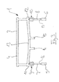
- FIG. 1 shows the part of a component 1 for thermal insulation that is essential to the invention shown, namely a U-shaped rail 2, which is used for fixing and fixing the position of tensile reinforcement bars 3 against an insulating body (not shown) serves, which is crossed by the tension rods.
- the U-rail is there from a U-base 4 and two U-legs 5 and 6, the circular recesses 7, 8 for the tension rods.
- the U-legs 5, 6 each extend on the side surfaces of the insulating body along its longitudinal extent and are oriented vertically, while the U-base is horizontal in the longitudinal direction of the insulator runs.
- the two U-legs 5, 6 are separate from the rest of the rail 2 retaining strips formed, which are provided on the U-base via locking connections 9, 10 Receiving sections 11, 12 are connected. About these rest connections it is possible to first equip the tension rods with the holding strips 5, 6 and then the entirety of tension rods and retaining strips on the U-rail set.
- a connecting bar 13 is provided parallel to the U-base 4, which is arched downward in the unloaded initial state. From this connecting bar 13, two projections extend in the form of Stop bars 14, 15 vertically downwards, where they are later inserted by the Tension bars applied and in the course of mounting the retaining strips in the receptacles be pressed elastically up until the final state shown in Figure 1 is reached in which the connecting bar 13 parallel without curvature extends to the U base 4.
- the reinforcement bar shown in Figure 1 3 from the stop bars 14, 15 down against the lower edges 16, 17 of the recesses 7, 8, which are provided in the holding strips 5, 6 are.
- each reinforcement bar is made of a total of four linear ones Sections acted on and so permanently and securely on the rail 2 and thus set in component 1 for thermal insulation.
- FIG. 2 is an enlarged detail the receptacle 12 for the retaining bar 6 shows and shows how the locking connection 10 is constructed:
- the receptacle 12 is approximately U-shaped with two barb - like, inwardly projecting lower edges, which the of inserted at the bottom and at its upper end, which acts on the receptacle arrow-shaped retaining bar.
- the present invention makes it easy to assemble and yet highly resilient position fixation for reinforcement bars and in particular provided for tension bars, the reinforcement bars between several Parts of the rail used are clamped.
Landscapes
- Engineering & Computer Science (AREA)
- Architecture (AREA)
- Physics & Mathematics (AREA)
- Electromagnetism (AREA)
- Civil Engineering (AREA)
- Structural Engineering (AREA)
- Reinforcement Elements For Buildings (AREA)
- Building Environments (AREA)
- Door And Window Frames Mounted To Openings (AREA)
- Wing Frames And Configurations (AREA)
- Insulated Conductors (AREA)
- Macromolecular Compounds Obtained By Forming Nitrogen-Containing Linkages In General (AREA)
Abstract
Description
Die Erfindung betrifft ein Bauelement zur Wärmedämmung zwischen zwei Bauteilen, insbesondere zwischen einem Gebäude und einem vorkragenden Außenteil, wobei das Bauelement aus einem in der Fuge zwischen den beiden Bauteile anzuordnenden Isolierkörper mit integrierten Bewehrungsstäben besteht, die sich quer zum Isolierkörper durch diesen hindurch erstrecken, und aus zumindest einer Schiene aus härterem Material als der Isolierkörper, die an oder nahe ihren beiden den Bauteilen zugewandten Seiten Ausnehmungen für die Bewehrungsstäbe aufweist, wobei die Schiene im Bereich zwischen jeweils den beiden Ausnehmungen für einen Bewehrungsstab einen ein Gegenlager für den Bewehrungsstab bildenden Vorsprung aufweist.The invention relates to a component for thermal insulation between two components, especially between a building and a projecting outer part, the component being arranged in a joint between the two components Insulating body with integrated reinforcing bars, which extends across extend to the insulating body through this, and from at least one Rail made of harder material than the insulating body that is on or near their two the sides facing the components have recesses for the reinforcing bars, the rail in the area between the two recesses for a rebar a counter bearing for the rebar Has a head start.
Ein solches Bauelement zur Wärmedämmung ist beispielsweise aus der DE-U 298 07 381 bekannt. Die genannte Schiene dient hierbei dazu, die Bewehrungsstäbe, insbesondere die Zugstäbe im relativ weichen Isolierkörpermaterial zu fixieren. Hierdurch lässt sich sicherstellen, dass die Bewehrungsstäbe den ihnen zugedachten Verlauf aufweisen, also beispielsweise die Zugstäbe senkrecht zur Längserstreckung des Isolierkörpers in horizontaler Ebene verlaufen.Such a component for thermal insulation is for example from DE-U 298 07 381 known. The rail mentioned here serves the reinforcing bars, in particular to fix the tension rods in the relatively soft insulating body material. This makes it possible to ensure that the reinforcing bars are intended for them Have course, so for example the tie rods perpendicular to the longitudinal extent of the insulating body run in the horizontal plane.
Üblicherweise beträgt die Länge eines Bauelements zur Wärmedämmung einen Meter und weist demgemäss eine Vielzahl von Bewehrungsstäben und insbesondere durch die Leiste festgelegten Zugstäben auf; wird nun ein solches Bauelement auf der Baustelle zu der Einbauposition transportiert, so erfolgt dies in der Regel durch Tragen und Angreifen zweier Zugstäbe. Hierdurch wird das gesamte Gewicht des transportierten Bauelements im Bereich der Ausnehmungen von der Leiste auf die beiden Zugstäbe übertragen. Insbesondere bei Bauelementen mit größerem Stabdurchmesser und demgemäss vergrößertem Gewicht kann dies zu Beschädigungen der Leiste im Bereich der Ausnehmungen führen, wodurch die Lagefixierung der beim Transportieren verwendeten Zugstäbe beeinträchtigt werden kann. The length of a component for thermal insulation is usually one Meters and accordingly has a variety of reinforcing bars and in particular tension rods set by the bar; now becomes such a component transported to the installation position on the construction site, this is done in the Usually by carrying and attacking two tension rods. This will make the whole Weight of the transported component in the area of the recesses Transfer the strip to the two tension rods. Especially with components with This can result in larger rod diameters and accordingly increased weight Damage to the bar in the area of the recesses, causing the Fixing the position of the tension rods used during transport are impaired can.
Hiervon ausgehend liegt der vorliegenden Erfindung die Aufgabe zugrunde, das eingangs beschriebene Bauelement zur Wärmedämmung dahingehend weiter zu verbessern, dass der Bereich der Lagefixierung der Bewehrungsstäbe durch die Schiene noch belastungsfähiger wird und hiermit selbst das Transportieren von Bauelementen mit vergrößertem Stabquerschnitt nicht zu einer Beschädigung der Leiste im Ausnehmungsbereich führt.Proceeding from this, the present invention has the object that Component for thermal insulation described at the beginning further improve that the area of fixing the reinforcement bars by the Rail becomes even more resilient and thus even the transport of Components with an enlarged rod cross section do not damage the Ledge in the recess area.
Diese Aufgabe wird erfindungsgemäß dadurch gelöst, dass die Ausnehmungen eine geschlossene Außenkontur aufweisen, dass sich der Vorsprung im Ausgangszustand ohne Bewehrungsstab soweit in die Flucht der beiden Ausnehmungen erstreckt, dass er diese Flucht teilweise verdeckt, und dass bei eingestecktem Bewehrungsstab dieser unter Verdrängung des Vorsprungs aus der Flucht zwischen den Rändern der Ausnehmungen und dem Vorsprung verspannt und festgelegt ist.This object is achieved in that the recesses have a closed outer contour that the projection in the initial state without the reinforcing bar extending as far as the alignment of the two recesses, that he partially hides this escape, and that with the reinforcing bar inserted this while displacing the projection from the flight between the edges of the recesses and the projection is clamped and fixed.
Zunächst einmal ist unschwer erkennbar, dass Ausnehmungen mit geschlossener Außenkontur etwaige auf die Ränder der Ausnehmungen wirkende Belastungen besser abfangen und aufnehmen können. Denn üblicherweise sind die Ausnehmungen der herkömmlichen Bauelemente einseitig geöffnet, um das seitliche Einstecken der Bewehrungsstäbe zu ermöglichen bzw. zu vereinfachen. Wenn nun diese Bewehrungsstäbe nicht mehr seitlich eingesetzt, sondern durch die Ausnehmungen hindurchgefädelt werden müssen, so erfordert dies - insbesondere bei teilweise aus geripptem Baustahl bestehenden Bewehrungsstäben - einen Ausnehmungsquerschnitt, der etwas größer als der Bewehrungsstabquerschnitt ist, um das Einstecken nicht zu behindern und auch um ein Beschädigen der Ausnehmungsränder beim Einstecken zu vermeiden. Diese vergrößerten Ausnehmungen würden jedoch auf der anderen Seite zu einer verschlechterten Lagefixierung führen aufgrund der fehlenden Anlage der Ausnehmungsränder an den Bewehrungsstäben über einen größeren Umfangsbereich der Bewehrungsstäbe.First of all, it is easy to see that recesses with closed Outer contour of any loads acting on the edges of the recesses intercept and absorb better. Because the recesses are usually of the conventional components open on one side to insert them from the side to enable or simplify the reinforcement bars. If so these rebars are no longer inserted laterally, but through the recesses must be threaded through, this requires - especially in reinforcement bars consisting partly of ribbed structural steel - a recess cross-section, which is slightly larger than the cross-section of the rebar in order to not to hinder the insertion and also to damage the recess edges to avoid when inserting. These enlarged recesses would, on the other hand, lead to a deterioration in the situation due to the absence of the recess edges on the reinforcement bars over a larger circumferential area of the reinforcing bars.
Hier schafft jedoch die vorliegende Erfindung Abhilfe, die bewusst zu große Ausnehmungen in Kauf nehmen kann, da zwei Ausnehmungen für einen Bewehrungsstab zusammen mit dem als Gegenlager fungierenden Vorsprung für eine optimale Lagefixierung sorgen. Auf der anderen Seite führt der geschlossene Umfangsbereich der Ausnehmungen dazu, dass die gesamten vom Bewehrungsstab auf den Ausnehmungsrand übertragenen Kräfte beidseitig vom Schienenmaterial aufgenommen werden können und somit die Belastbarkeit dieser Lagefixierung weitaus höher ist als bei den Ausführungen mit einseitig offenen und ein seitliches Einstecken der Bewehrungsstäbe ermöglichenden Ausnehmungsrändern. Dadurch, dass die Schiene für eine noch einmal stark verbesserte Lagefixierung der Bewehrungsstäbe gegenüber dem Isolierkörper sorgt, kann sogar auf das sonst übliche Anschweißen von Verteilerstäben beabstandet und parallel zum Isolierkörper verzichtet werden.Here, however, the present invention remedies the deliberately too large recesses can accept, since two recesses for a reinforcing bar together with the projection acting as a counter bearing for an optimal Ensure position fixation. On the other hand, the closed peripheral area leads of the recesses so that the entire from the reinforcement bar to the Transmitted edge forces absorbed on both sides of the rail material can be and thus the resilience of this position fixing far is higher than the versions with one-sided opening and a lateral insertion of the reinforcement bars enabling recess edges. As a result of that the rail for a further greatly improved position fixation of the reinforcing bars against the insulating body, can even be done on the usual welding spaced from distribution bars and dispensed parallel to the insulating body become.
Zweckmäßigerweise besteht der Vorsprung aus einer sich in Längsrichtung der Schiene erstreckenden Anschlagleiste, die elastisch nachgiebig ausgeführt ist, so dass dem Bewehrungsstab ein linienförmiger und damit durchgehender Anlagebereich zur Verfügung gestellt wird. Die Anschlagleiste, die in Vertikalrichtung und senkrecht zu der Erstreckung der Bewehrungsstäbe orientiert ist, sorgt aufgrund ihrer elastischen Nachgiebigkeit für die nötige Verspannung und Festlegung des Bewehrungsstabs zwischen den Rändern der Ausnehmung und dem Vorsprung.Advantageously, the projection consists of a in the longitudinal direction Rail-extending stop bar, which is designed to be resilient, so that the reinforcement bar has a linear and therefore continuous contact area is made available. The stop bar, the vertical and is oriented perpendicular to the extension of the reinforcing bars their elastic compliance for the necessary bracing and fixing the Reinforcement bars between the edges of the recess and the protrusion.
Der Vorsprung kann aber auch aus einem elastisch und/oder plastisch verformbaren Material, also z. B. aus Gummi oder Isolierschaum bestehen, um ein geeignetes Gegenlager (beim Isolierschaum nach dem Aushärten) zu bilden.However, the projection can also be made of an elastically and / or plastically deformable one Material, e.g. B. consist of rubber or insulating foam to a suitable To form counter bearings (in the case of insulating foam after curing).
Was die Schiene betrifft, so empfiehlt es sich, wenn sie einen U-förmigen Querschnitt aufweist, wenn sie mit ihrer Basis und ihren Schenkeln den Isolierkörper zumindest in Teilen umgibt und wenn die Ausnehmungen jeweils in den Schenkeln der U-Schiene angeordnet sind. Hierdurch erhält man einen großflächigen Anlagebereich zwischen Schiene und Isolierkörper und somit eine verbesserte Lagefixierung der hieran festgelegten Bewehrungsstäbe, da die U-Schiene aufgrund der festen Verbindung mit den Bewehrungsstäben der Oberfläche der Bewehrungsstäbe zuzurechnen ist und diese entsprechend vergrößert.As for the rail, it is recommended if it has a U-shaped cross section if the base and the legs of the insulating body at least in parts and if the recesses in each case in the legs the U-rail are arranged. This gives you a large investment area between rail and insulating body and thus an improved position fixation of the reinforcing bars specified here, because the U-rail due to the fixed connection with the reinforcing bars of the surface of the reinforcing bars is attributed and enlarged accordingly.
Um trotz des in die Flucht der beiden Ausnehmungen vorstehenden Vorsprungs die Montage der Bewehrungsstäbe zu ermöglichen, empfiehlt es sich insbesondere, dass die Schiene mehrteilig ausgebildet ist derart, dass die Ausnehmungen in separaten Halteleisten vorgesehen sind und dass die Halteleisten an einer gemeinsamen Schienenbasis festgelegt sind. Hierdurch ist es möglich, zunächst die Bewehrungsstäbe in die beiden Halteleisten einzustecken und dann die Gesamtheit aus Bewehrungsstäben und Halteleisten auf die Schiene aufzustecken, wobei gleichzeitig der Vorsprung elastisch aus seiner Ausgangslage verdrängt wird. Ist die Schiene mit derartigen Halteleisten mehrteilig ausgeführt, so bezieht sich das vorstehend erwähnte Erstrecken des Vorsprungs in die Flucht der beiden Ausnehmungen für einen Bewehrungsstab auf einen montierten Zustand der Halteleisten in die Schiene ohne eingesetzte Bewehrungsstäbe. Ein solcher Zustand dient jedoch nur zur Beschreibung der geometrischen Verhältnisse, ohne jedoch in der Praxis verwirklicht zu werden, da hierdurch die Vorteile der Halteleisten zunichte gemacht werden würden.To despite the protrusion protruding into the alignment of the two recesses To enable the reinforcement bars to be installed, it is particularly recommended that the rail is formed in several parts such that the recesses in separate Retaining strips are provided and that the retaining strips are on a common Rail base are set. This makes it possible to start with the reinforcement bars insert into the two retaining strips and then the whole from reinforcing bars and retaining strips on the rail, whereby at the same time the projection is elastically displaced from its starting position. is the rail is designed in several parts with such retaining strips, so that relates the aforementioned extension of the projection into the alignment of the two recesses for a rebar on an assembled state of the retaining strips into the rail without reinforcement bars inserted. However, such a condition serves only to describe the geometric relationships, but without in the Practice to be realized, as this nullifies the advantages of the retaining strips would be made.
Bezüglich der Art der Festlegung der Halteleisten an der Schienenbasis ist insbesondere eine Rastverbindung empfehlenswert, wobei aber auch sonstige formschlüssige und einfach zu montierende Festlegungsarten Anwendung finden können.Regarding the type of fixing of the retaining strips on the rail base is particularly a snap connection is recommended, but also other positive and easy to install types of fixing can be used.
Besonders zweckmäßig ist es, wenn die Schiene aus zwei U-Schenkeln und einer U-Basis und einer zusätzlich zur U-Basis an die beiden U-Schenkel angeschlossenen Verbindungsleiste besteht, die den Vorsprung trägt und hierdurch für die elastische Nachgiebigkeit des Vorsprungs sorgt. Hierzu ist die Verbindungsleiste zweckmäßigerweise gewölbt ausgeführt, wobei die Nachgiebigkeit des Vorsprungs wird durch die Wölbung der Verbindungsleiste zur Verfügung gestellt wird; d. h., dass die Verbindungsleiste vorgewölbt ist und bei Beaufschlagung des Vorsprungs durch die Bewehrungsstäbe entgegen ihrer Wölbung elastisch zurückgedrängt wird, bis sie einen ungefähr zu der U-Basis parallelen Verlauf aufweist.It is particularly useful if the rail consists of two U-legs and one U-base and one connected to the two U-legs in addition to the U-base Connection strip is there, which carries the projection and thereby for the elastic Flexibility of the lead ensures. For this is the connection bar expediently designed arched, the flexibility of the projection is provided by the curvature of the connecting bar; d. H., that the connecting bar is bulged and when the projection is applied elastically pushed back by the reinforcing bars against their curvature until it is approximately parallel to the U-base.
Zum Vorsprung sei erwähnt, dass dieser insbesondere aus zwei parallel zueinander verlaufenden Anschlagleisten bestehen kann, um als Gegenlager eine stabile Anlage für die Bewehrungsstäbe zur Verfügung zu stellen. Außerdem liegt der Vorsprung unter Vorspannung an dem Bewehrungsstab an und legt ihn aufgrund der Vorspannung gegen den Rand der Ausnehmung unverschiebbar fest. Regarding the lead, it should be mentioned that this consists in particular of two parallel to each other extending stop strips can exist to provide a stable counter bearing To provide attachment for the reinforcing bars. In addition, the Prestressed projection on the reinforcing bar and sets it due the bias against the edge of the recess is immovable.
Die spätere Lage des Vorsprungs und der Verbindungsleiste im montierten Zustand ist natürlich bei der Formgebung für den Isolierkörper zu berücksichtigen, wobei zweckmäßigerweise der Bereich zwischen U-Basis und Verbindungsleiste mit Isoliermaterial oder etwa mit feuerhemmendem Dämmmaterial ausgefüllt sein sollte.The later position of the projection and the connecting bar in the assembled state is of course to be considered when designing the insulating body, expediently the area between the U-base and the connecting strip be filled with insulating material or with fire-retardant insulation material should.
Der mehrteilige Aufbau der Schiene bringt den weiteren Vorteil mit sich, dass die Halteleisten einerseits und die Schiene andererseits hinsichtlich ihres Materials an die jeweiligen Anforderungen angepasst sein können. So können beispielsweise die Halteleisten aus anderem und insbesondere weicherem und festerem Material als die Schiene bestehen, welche aus demgegenüber steiferem Material ausgebildet sein kann. Während die Halteleisten zum einen das Einbringen der Ausnehmungen begünstigen sollen, müssen sie aber auch stabil genug sein im die Ausnehmungen umgebenden Randbereich, um dort die auftretenden Kräfte besser aufnehmen zu können. Und die Schiene sollte vor allem möglichst verwindungssteif sein, um hierdurch eine optimale Lagefixierung der Bewehrungsstäbe gegenüber dem Isolierkörper zu gewährleisten.The multi-part structure of the rail has the further advantage that the Holding strips on the one hand and the rail on the other with regard to their material the respective requirements can be adapted. For example the holding strips made of different and in particular softer and firmer material than the rail, which are made of stiffer material can be. While the holding strips firstly the insertion of the recesses favor, they must also be stable enough in the recesses surrounding edge area in order to improve the forces occurring there to be able to record. And above all, the rail should be as rigid as possible be in order to thereby optimally fix the reinforcement bars to ensure the insulating body.
Weitere Merkmale und Vorteile der vorliegenden Erfindung ergeben sich aus der nachfolgenden Beschreibung eines Ausführungsbeispiels anhand der Zeichnung. Hierbei zeigen
- Figur 1
- ein erfindungsgemäßes Bauelement zur Wärmedämmung auszugsweise in Seitenansicht;
Figur 2- ein Detail des Bauelementes zur Wärmedämmung aus Figur 1; und
Figur 3- das Bauelement aus Figur 1 in der Ausgangsstellung ohne eingesteckte Bewehrungsstäbe.
- Figure 1
- an inventive component for thermal insulation in part in side view;
- Figure 2
- a detail of the component for thermal insulation from Figure 1; and
- Figure 3
- the component from Figure 1 in the starting position without inserted reinforcing bars.
In Figur 1 ist der erfindungswesentliche Teil eines Bauelements 1 zur Wärmedämmung
dargestellt, nämlich eine U-förmige Schiene 2, die zur Festlegung und Lagefixierung
von Zugbewehrungsstäben 3 gegenüber einem (nicht dargestellten) Isolierkörper
dient, der von den Zugstäben durchquert wird. Die U-Schiene besteht
aus einer U-Basis 4 und zwei U-Schenkeln 5 und 6, die kreisförmige Ausnehmungen
7, 8 für die Zugstäbe aufweisen. Die U-Schenkel 5, 6 erstrecken sich jeweils
an den Seitenflächen des Isolierkörpers entlang dessen Längserstreckung und
sind vertikal orientiert, während die U-Basis horizontal in Längsrichtung des Isolierkörpers
verläuft.FIG. 1 shows the part of a component 1 for thermal insulation that is essential to the invention
shown, namely a
Die beiden U-Schenkel 5, 6 sind als von der restlichen Schiene 2 separate Halteleisten
ausgebildet, die über Rastverbindungen 9, 10 mit an der U-Basis vorgesehenen
Aufnahmeabschnitten 11, 12 verbunden sind. Über diese Rastverbindungen
ist es möglich, zunächst die Zugstäbe mit den Halteleisten 5, 6 zu bestücken und
anschließend die Gesamtheit aus Zugstäben und Halteleisten an der U-Schiene
festzulegen.The two U-legs 5, 6 are separate from the rest of the
Wie aus Figur 3, die den Ausgangszustand ohne eingesteckte Bewehrungsstäbe
zeigt, ersichtlich ist, ist parallel zur U-Basis 4 eine Verbindungsleiste 13 vorgesehen,
die im unbelasteten Ausgangszustand nach unten gewölbt ausgebildet ist.
Von dieser Verbindungsleiste 13 aus erstrecken sich zwei Vorsprünge in Form von
Anschlagleisten 14, 15 vertikal nach unten, wo sie später von den eingesteckten
Zugstäben beaufschlagt und im Zuge des Montierens der Halteleisten in die Aufnahmen
elastisch nach oben gedrückt werden, bis der in Figur 1 dargestellte Endzustand
erreicht ist, in dem sich die Verbindungsleiste 13 ohne Wölbung parallel
zur U-Basis 4 erstreckt. In diesem Endzustand wird der in Figur 1 gezeigte Bewehrungsstab
3 von den Anschlagleisten 14, 15 nach unten gegen die unteren Ränder
16, 17 der Ausnehmungen 7, 8 gedrückt, die in den Halteleisten 5, 6 vorgesehen
sind. Hierdurch wird jeder Bewehrungsstab von insgesamt vier linienförmigen
Abschnitten beaufschlagt und so dauerhaft und sicher an der Schiene 2 und somit
im Bauelement 1 zur Wärmedämmung festgelegt.As from Figure 3, the initial state without inserted reinforcing bars
shows, can be seen, a connecting
Der Vollständigkeit halber sei auf Figur 2 verwiesen, die eine Ausschnittsvergrößerung
der Aufnahme 12 für die Halteleiste 6 zeigt und erkennen lässt, wie die Rastverbindung
10 aufgebaut ist: Die Aufnahme 12 ist ungefähr U-förmig ausgebildet
mit zwei widerhakenähnlichen, nach innen ragenden unteren Rändern, die die von
unten eingesteckte und an ihrem oberen, die Aufnahme beaufschlagenden Ende
pfeilförmig ausgebildete Halteleiste aufnimmt. Durch diese Steckverbindungen ist
eine einfache Montage gewährleistet bei gleichzeitig dauerhafter Festlegung der
Halteleiste an der restlichen Schiene, die dazu führt, dass die Halteleiste 6 und die
restliche Schiene im Einbauzustand wie ein einstöckiges Bauteil wirken. For the sake of completeness, reference is made to FIG. 2, which is an enlarged detail
the
Zusammenfassend wird durch die vorliegende Erfindung eine einfach montierbare und dennoch hoch belastbare Lagefixierung für Bewehrungsstäbe und insbesondere für Zugstäbe zur Verfügung gestellt, wobei die Bewehrungsstäbe zwischen mehreren Teilen der verwendeten Schiene verspannt sind.In summary, the present invention makes it easy to assemble and yet highly resilient position fixation for reinforcement bars and in particular provided for tension bars, the reinforcement bars between several Parts of the rail used are clamped.
Claims (17)
dadurch gekennzeichnet, dass die Ausnehmungen (7, 8) eine geschlossene Außenkontur aufweisen, dass sich der Vorsprung (14, 15) im Ausgangszustand ohne Bewehrungsstab (3) so weit in die Flucht der beiden Ausnehmungen erstreckt, dass er diese Flucht teilweise verdeckt, und dass der eingesteckte Bewehrungsstab unter Verdrängung des Vorsprungs (14, 15) aus der Flucht zwischen den Rändern (16, 17) der Ausnehmungen und dem Vorsprung (14, 15) verspannt und festgelegt ist.Component for thermal insulation between two components, in particular between a building and a cantilevered outer part, the component consisting of an insulating body to be arranged in the joint between the two components with integrated reinforcing bars (3) extending through the insulating body and through it at least one rail (2) made of harder material than the insulating body, which has recesses (7, 8) for the reinforcing bars on or near its two sides facing the components, the rail in the area between the two recesses for a reinforcing bar and a counter bearing for the reinforcement bar forming projection (14, 15),
characterized in that the recesses (7, 8) have a closed outer contour, that the projection (14, 15) in the initial state without a reinforcing bar (3) extends so far into the alignment of the two recesses that it partially covers this alignment, and that the inserted reinforcing bar is clamped and fixed while displacing the projection (14, 15) from the alignment between the edges (16, 17) of the recesses and the projection (14, 15).
dadurch gekennzeichnet, dass der Vorsprung (14, 15) aus einer sich in Längsrichtung der Schiene (2) erstreckenden Anschlagleiste besteht, und dass die Anschlagleiste elastisch nachgiebig ausgeführt ist.Component for thermal insulation according to claim 1
characterized in that the projection (14, 15) consists of a stop bar extending in the longitudinal direction of the rail (2), and in that the stop bar is designed to be resilient.
dadurch gekennzeichnet, dass die Anschlagleiste (14, 15) in Vertikalrichtung und senkrecht zur der Erstreckung der Bewehrungsstäbe (3) orientiert ist. Component for thermal insulation according to claim 2,
characterized in that the stop bar (14, 15) is oriented in the vertical direction and perpendicular to the extension of the reinforcing bars (3).
dadurch gekennzeichnet, dass der Vorsprung aus einem elastisch und/oder plastisch nachgiebigen Material besteht.Component for thermal insulation according to one of the preceding claims,
characterized in that the projection consists of an elastically and / or plastically resilient material.
dadurch gekennzeichnet, dass das elastisch und/oder plastisch nachgiebige Material Gummi oder Isolierschaum ist.Component for thermal insulation according to one of the preceding claims,
characterized in that the elastic and / or plastically resilient material is rubber or insulating foam.
dadurch gekennzeichnet, dass die Schiene (2) einen U-förmigen Querschnitt aufweist, dass die U-Schiene mit ihrer Basis (4) und ihren Schenkeln (5, 6) den Isolierkörper zumindest in Teilen umgibt, und dass die Ausnehmungen (7, 8) jeweils in den Schenkeln der U-Schiene angeordnet sind.Component for thermal insulation according to one of the preceding claims,
characterized in that the rail (2) has a U-shaped cross-section, that the base of the U-rail (4) and its legs (5, 6) surrounds the insulating body at least in part, and that the recesses (7, 8 ) are each arranged in the legs of the U-rail.
dadurch gekennzeichnet, dass die Schiene (2) mehrteilig ausgebildet ist derart, dass die Ausnehmungen in separaten Halteleisten (5, 6) vorgesehen sind, und dass die Halteleisten an einer gemeinsamen Schienenbasis (4) festgelegt sind.Component for thermal insulation according to one of the preceding claims,
characterized in that the rail (2) is constructed in several parts such that the recesses are provided in separate holding strips (5, 6) and that the holding strips are fixed to a common rail base (4).
dadurch gekennzeichnet, dass die Festlegung der Halteleisten (5, 6) an der Schienenbasis (4) über eine Rast-, Schweiß- oder Klebeverbindung (9, 10) erfolgt. Component for thermal insulation according to claim 7,
characterized in that the holding strips (5, 6) are fixed to the rail base (4) via a snap-in, welded or adhesive connection (9, 10).
dadurch gekennzeichnet, dass die Schiene (2) aus zwei U-Schenkeln (5, 6) und einer U-Basis (4) besteht, und dass zusätzlich zur U-Basis eine an die beiden U-Schenkel angeschlossene Verbindungsleiste (13) vorgesehen ist.Component for thermal insulation according to one of the preceding claims,
characterized in that the rail (2) consists of two U-legs (5, 6) and a U-base (4), and that in addition to the U-base a connecting bar (13) connected to the two U-legs is provided ,
dadurch gekennzeichnet, dass die Verbindungsleiste (13) den Vorsprung (14, 15) trägt.Component for thermal insulation according to claim 9,
characterized in that the connecting bar (13) carries the projection (14, 15).
dadurch gekennzeichnet, dass die Verbindungsleiste (13) zwei parallel zueinander verlaufende Anschlagleisten (14, 15) trägt.Component for thermal insulation according to claim 10 and according to claims 2 and 3,
characterized in that the connecting bar (13) carries two stop bars (14, 15) running parallel to one another.
dadurch gekennzeichnet, dass die Verbindungsleiste (13) gewölbt ausgeführt ist und dass die elastische Nachgiebigkeit des Vorsprungs (14, 15) durch die Wölbung der Verbindungsleiste zur Verfügung gestellt wird.Component for thermal insulation according to at least claim 9,
characterized in that the connecting bar (13) is curved and that the elastic flexibility of the projection (14, 15) is provided by the curvature of the connecting bar.
dadurch gekennzeichnet, dass der Vorsprung (14, 15) unter Vorspannung an dem Bewehrungsstab (3) anliegt, ihn aufgrund der Vorspannung gegen den Rand (16, 17) der Ausnehmungen (7, 8) drückt und so unverschiebbar festlegt.Component for thermal insulation according to one of the preceding claims,
characterized in that the projection (14, 15) rests under prestress on the reinforcing bar (3), presses it against the edge (16, 17) of the recesses (7, 8) due to the prestress and thus fixes it immovably.
dadurch gekennzeichnet, dass der Bereich zwischen U-Basis (4) und Verbindungsleiste (13) mit Isoliermaterial ausgefüllt ist. Component for thermal insulation according to claim 9,
characterized in that the area between the U-base (4) and the connecting strip (13) is filled with insulating material.
dadurch gekennzeichnet, dass sich die Verbindungsleiste (13) in etwa parallel zur U-Basis (4) erstreckt,Component for thermal insulation according to claim 9,
characterized in that the connecting strip (13) extends approximately parallel to the U-base (4),
dadurch gekennzeichnet, dass die Ausnehmungen (7, 8) aus dem Querschnitt der Bewehrungsstäbe (3) angepassten und insbesondere runden Bohrungen bestehen.Component for thermal insulation according to one of the preceding claims,
characterized in that the recesses (7, 8) consist of the cross section of the reinforcing bars (3) and in particular round bores.
dadurch gekennzeichnet, dass die Halteleisten (5, 6) aus anderem und insbesondere weicherem und festerem Material als die Schiene (2) besteht, welche aus demgegenüber steifem Material ausgebildet ist.Component according to Claim 3,
characterized in that the holding strips (5, 6) consist of a different and in particular softer and stronger material than the rail (2), which is made of a material that is stiff in contrast.
Applications Claiming Priority (2)
| Application Number | Priority Date | Filing Date | Title |
|---|---|---|---|
| DE10036525A DE10036525A1 (en) | 2000-07-27 | 2000-07-27 | Component for thermal insulation |
| DE10036525 | 2000-07-27 |
Publications (3)
| Publication Number | Publication Date |
|---|---|
| EP1176263A2 true EP1176263A2 (en) | 2002-01-30 |
| EP1176263A3 EP1176263A3 (en) | 2003-01-08 |
| EP1176263B1 EP1176263B1 (en) | 2005-03-16 |
Family
ID=7650358
Family Applications (1)
| Application Number | Title | Priority Date | Filing Date |
|---|---|---|---|
| EP01115445A Expired - Lifetime EP1176263B1 (en) | 2000-07-27 | 2001-06-27 | Heat insulating building element |
Country Status (3)
| Country | Link |
|---|---|
| EP (1) | EP1176263B1 (en) |
| AT (1) | ATE291132T1 (en) |
| DE (2) | DE10036525A1 (en) |
Citations (1)
| Publication number | Priority date | Publication date | Assignee | Title |
|---|---|---|---|---|
| DE29807381U1 (en) | 1998-04-23 | 1998-08-13 | Schöck Bauteile GmbH, 76534 Baden-Baden | Component for thermal insulation |
Family Cites Families (2)
| Publication number | Priority date | Publication date | Assignee | Title |
|---|---|---|---|---|
| DE4423413A1 (en) * | 1994-07-05 | 1996-01-11 | Schoeck Bauteile Gmbh | Component for thermal insulation in buildings |
| DE19731093B4 (en) * | 1997-07-19 | 2004-07-15 | Schöck Bauteile GmbH | Component for thermal insulation |
-
2000
- 2000-07-27 DE DE10036525A patent/DE10036525A1/en not_active Withdrawn
-
2001
- 2001-06-27 AT AT01115445T patent/ATE291132T1/en active
- 2001-06-27 DE DE50105594T patent/DE50105594D1/en not_active Expired - Lifetime
- 2001-06-27 EP EP01115445A patent/EP1176263B1/en not_active Expired - Lifetime
Patent Citations (1)
| Publication number | Priority date | Publication date | Assignee | Title |
|---|---|---|---|---|
| DE29807381U1 (en) | 1998-04-23 | 1998-08-13 | Schöck Bauteile GmbH, 76534 Baden-Baden | Component for thermal insulation |
Also Published As
| Publication number | Publication date |
|---|---|
| ATE291132T1 (en) | 2005-04-15 |
| EP1176263A3 (en) | 2003-01-08 |
| EP1176263B1 (en) | 2005-03-16 |
| DE10036525A1 (en) | 2002-02-07 |
| DE50105594D1 (en) | 2005-04-21 |
Similar Documents
| Publication | Publication Date | Title |
|---|---|---|
| CH676615A5 (en) | ||
| EP1832690A2 (en) | Building element for heat insulation | |
| AT4958U1 (en) | DEVICE FOR SUPPORTING WINDOW OR DOOR FRAMES ON THE LIMITATION OF A WALL OPENING | |
| DE102011122589A1 (en) | Component for thermal insulation | |
| EP0831183B1 (en) | Construction element for heat insulation | |
| DE4102332A1 (en) | Balcony mounting - has fibre-reinforced plastic absorbing tension load and passing through insulating body | |
| DE19543768A1 (en) | Attachment for balcony on building | |
| DE102009003869A1 (en) | Longitudinal plug-in connector or U-shaped plug-in connector for spacer hollow profile for insulating glass plane, has base part and two brackets arranged in area of longitudinal side edges | |
| EP0834622B1 (en) | Heat insulated connection between external concrete elements, particularly cantilever parts, and building | |
| EP0778389B1 (en) | Plastic straight connector for hollow spacer profiles in insulating glazing | |
| DE102006032444A1 (en) | Construction element used as heat insulation between two components to be covered with concrete comprises a connecting element traversing and fixing an insulating body relative to a compression and/or transverse force element and tie rods | |
| DE102005039025A1 (en) | Component for thermal insulation | |
| EP0599051A1 (en) | Supporting element for panes of windows, doors or the like | |
| EP1176263B1 (en) | Heat insulating building element | |
| DE29602634U1 (en) | Insulating pane with hollow rungs inserted between the glass panes | |
| DE102019118363B4 (en) | Arrangement for connecting a structural part with an external steel part in front of the structural part | |
| DE8129873U1 (en) | PIPE HOLDER | |
| DE3525347A1 (en) | FOR HOLDING HEATING TUBES OF UNDERFLOOR HEATING CERTAIN HOLDING CLIP | |
| EP1878840B1 (en) | Element for heat insulation between two cast concrete building parts | |
| EP1830029A2 (en) | Louvre construction for façades | |
| EP0745733A1 (en) | Cantilever plate element and/or seal element for reinforced building constructions | |
| AT408364B (en) | FORMWORK SYSTEM FOR A COVERED CONCRETE MASONRY | |
| EP1754840B1 (en) | Building element for heat insulation | |
| DE29808988U1 (en) | Glazed seam insert | |
| DE202025102353U1 (en) | Stop device |
Legal Events
| Date | Code | Title | Description |
|---|---|---|---|
| PUAI | Public reference made under article 153(3) epc to a published international application that has entered the european phase |
Free format text: ORIGINAL CODE: 0009012 |
|
| AK | Designated contracting states |
Kind code of ref document: A2 Designated state(s): AT BE CH CY DE DK ES FI FR GB GR IE IT LI LU MC NL PT SE TR |
|
| AX | Request for extension of the european patent |
Free format text: AL;LT;LV;MK;RO;SI |
|
| PUAL | Search report despatched |
Free format text: ORIGINAL CODE: 0009013 |
|
| AK | Designated contracting states |
Kind code of ref document: A3 Designated state(s): AT BE CH CY DE DK ES FI FR GB GR IE IT LI LU MC NL PT SE TR |
|
| AX | Request for extension of the european patent |
Free format text: AL;LT;LV;MK;RO;SI |
|
| 17P | Request for examination filed |
Effective date: 20030212 |
|
| AKX | Designation fees paid |
Designated state(s): AT BE CH CY DE DK ES FI FR GB GR IE IT LI LU MC NL PT SE TR |
|
| 17Q | First examination report despatched |
Effective date: 20031230 |
|
| GRAP | Despatch of communication of intention to grant a patent |
Free format text: ORIGINAL CODE: EPIDOSNIGR1 |
|
| RAP1 | Party data changed (applicant data changed or rights of an application transferred) |
Owner name: SCHOECK BAUTEILE GMBH |
|
| GRAS | Grant fee paid |
Free format text: ORIGINAL CODE: EPIDOSNIGR3 |
|
| GRAA | (expected) grant |
Free format text: ORIGINAL CODE: 0009210 |
|
| AK | Designated contracting states |
Kind code of ref document: B1 Designated state(s): AT BE CH CY DE DK ES FI FR GB GR IE IT LI LU MC NL PT SE TR |
|
| PG25 | Lapsed in a contracting state [announced via postgrant information from national office to epo] |
Ref country code: FI Free format text: LAPSE BECAUSE OF FAILURE TO SUBMIT A TRANSLATION OF THE DESCRIPTION OR TO PAY THE FEE WITHIN THE PRESCRIBED TIME-LIMIT Effective date: 20050316 Ref country code: TR Free format text: LAPSE BECAUSE OF FAILURE TO SUBMIT A TRANSLATION OF THE DESCRIPTION OR TO PAY THE FEE WITHIN THE PRESCRIBED TIME-LIMIT Effective date: 20050316 |
|
| REG | Reference to a national code |
Ref country code: GB Ref legal event code: FG4D Free format text: NOT ENGLISH |
|
| REG | Reference to a national code |
Ref country code: CH Ref legal event code: EP |
|
| REG | Reference to a national code |
Ref country code: IE Ref legal event code: FG4D Free format text: GERMAN |
|
| REF | Corresponds to: |
Ref document number: 50105594 Country of ref document: DE Date of ref document: 20050421 Kind code of ref document: P |
|
| PG25 | Lapsed in a contracting state [announced via postgrant information from national office to epo] |
Ref country code: DK Free format text: LAPSE BECAUSE OF FAILURE TO SUBMIT A TRANSLATION OF THE DESCRIPTION OR TO PAY THE FEE WITHIN THE PRESCRIBED TIME-LIMIT Effective date: 20050616 Ref country code: GR Free format text: LAPSE BECAUSE OF FAILURE TO SUBMIT A TRANSLATION OF THE DESCRIPTION OR TO PAY THE FEE WITHIN THE PRESCRIBED TIME-LIMIT Effective date: 20050616 |
|
| PG25 | Lapsed in a contracting state [announced via postgrant information from national office to epo] |
Ref country code: CY Free format text: LAPSE BECAUSE OF FAILURE TO SUBMIT A TRANSLATION OF THE DESCRIPTION OR TO PAY THE FEE WITHIN THE PRESCRIBED TIME-LIMIT Effective date: 20050627 Ref country code: ES Free format text: LAPSE BECAUSE OF FAILURE TO SUBMIT A TRANSLATION OF THE DESCRIPTION OR TO PAY THE FEE WITHIN THE PRESCRIBED TIME-LIMIT Effective date: 20050627 |
|
| PG25 | Lapsed in a contracting state [announced via postgrant information from national office to epo] |
Ref country code: MC Free format text: LAPSE BECAUSE OF NON-PAYMENT OF DUE FEES Effective date: 20050630 |
|
| GBT | Gb: translation of ep patent filed (gb section 77(6)(a)/1977) |
Effective date: 20050630 |
|
| PG25 | Lapsed in a contracting state [announced via postgrant information from national office to epo] |
Ref country code: PT Free format text: LAPSE BECAUSE OF FAILURE TO SUBMIT A TRANSLATION OF THE DESCRIPTION OR TO PAY THE FEE WITHIN THE PRESCRIBED TIME-LIMIT Effective date: 20050907 |
|
| REG | Reference to a national code |
Ref country code: CH Ref legal event code: NV Representative=s name: R. A. EGLI & CO. PATENTANWAELTE |
|
| PLBE | No opposition filed within time limit |
Free format text: ORIGINAL CODE: 0009261 |
|
| STAA | Information on the status of an ep patent application or granted ep patent |
Free format text: STATUS: NO OPPOSITION FILED WITHIN TIME LIMIT |
|
| 26N | No opposition filed |
Effective date: 20051219 |
|
| EN | Fr: translation not filed | ||
| PG25 | Lapsed in a contracting state [announced via postgrant information from national office to epo] |
Ref country code: SE Free format text: LAPSE BECAUSE OF FAILURE TO SUBMIT A TRANSLATION OF THE DESCRIPTION OR TO PAY THE FEE WITHIN THE PRESCRIBED TIME-LIMIT Effective date: 20050616 |
|
| PG25 | Lapsed in a contracting state [announced via postgrant information from national office to epo] |
Ref country code: FR Free format text: LAPSE BECAUSE OF NON-PAYMENT OF DUE FEES Effective date: 20050630 |
|
| PG25 | Lapsed in a contracting state [announced via postgrant information from national office to epo] |
Ref country code: FR Free format text: LAPSE BECAUSE OF NON-PAYMENT OF DUE FEES Effective date: 20050316 |
|
| PGFP | Annual fee paid to national office [announced via postgrant information from national office to epo] |
Ref country code: LU Payment date: 20110622 Year of fee payment: 11 |
|
| PGFP | Annual fee paid to national office [announced via postgrant information from national office to epo] |
Ref country code: IE Payment date: 20120619 Year of fee payment: 12 |
|
| PGFP | Annual fee paid to national office [announced via postgrant information from national office to epo] |
Ref country code: IT Payment date: 20120623 Year of fee payment: 12 |
|
| REG | Reference to a national code |
Ref country code: IE Ref legal event code: MM4A |
|
| PG25 | Lapsed in a contracting state [announced via postgrant information from national office to epo] |
Ref country code: IE Free format text: LAPSE BECAUSE OF NON-PAYMENT OF DUE FEES Effective date: 20130627 |
|
| PG25 | Lapsed in a contracting state [announced via postgrant information from national office to epo] |
Ref country code: IT Free format text: LAPSE BECAUSE OF NON-PAYMENT OF DUE FEES Effective date: 20130627 |
|
| PG25 | Lapsed in a contracting state [announced via postgrant information from national office to epo] |
Ref country code: LU Free format text: LAPSE BECAUSE OF NON-PAYMENT OF DUE FEES Effective date: 20130627 |
|
| PGFP | Annual fee paid to national office [announced via postgrant information from national office to epo] |
Ref country code: DE Payment date: 20200507 Year of fee payment: 20 |
|
| PGFP | Annual fee paid to national office [announced via postgrant information from national office to epo] |
Ref country code: BE Payment date: 20200622 Year of fee payment: 20 Ref country code: GB Payment date: 20200625 Year of fee payment: 20 Ref country code: NL Payment date: 20200622 Year of fee payment: 20 |
|
| PGFP | Annual fee paid to national office [announced via postgrant information from national office to epo] |
Ref country code: AT Payment date: 20200618 Year of fee payment: 20 |
|
| PGFP | Annual fee paid to national office [announced via postgrant information from national office to epo] |
Ref country code: CH Payment date: 20200630 Year of fee payment: 20 |
|
| REG | Reference to a national code |
Ref country code: DE Ref legal event code: R071 Ref document number: 50105594 Country of ref document: DE |
|
| REG | Reference to a national code |
Ref country code: NL Ref legal event code: MK Effective date: 20210626 Ref country code: CH Ref legal event code: PL |
|
| REG | Reference to a national code |
Ref country code: BE Ref legal event code: MK Effective date: 20210627 |
|
| REG | Reference to a national code |
Ref country code: GB Ref legal event code: PE20 Expiry date: 20210626 |
|
| REG | Reference to a national code |
Ref country code: AT Ref legal event code: MK07 Ref document number: 291132 Country of ref document: AT Kind code of ref document: T Effective date: 20210627 |
|
| PG25 | Lapsed in a contracting state [announced via postgrant information from national office to epo] |
Ref country code: GB Free format text: LAPSE BECAUSE OF EXPIRATION OF PROTECTION Effective date: 20210626 |