EP1180410A2 - Schweissverbindung mit zwei Blechen - Google Patents
Schweissverbindung mit zwei Blechen Download PDFInfo
- Publication number
- EP1180410A2 EP1180410A2 EP01119280A EP01119280A EP1180410A2 EP 1180410 A2 EP1180410 A2 EP 1180410A2 EP 01119280 A EP01119280 A EP 01119280A EP 01119280 A EP01119280 A EP 01119280A EP 1180410 A2 EP1180410 A2 EP 1180410A2
- Authority
- EP
- European Patent Office
- Prior art keywords
- sheet
- edge
- tabs
- welded
- angled
- Prior art date
- Legal status (The legal status is an assumption and is not a legal conclusion. Google has not performed a legal analysis and makes no representation as to the accuracy of the status listed.)
- Granted
Links
- 238000003466 welding Methods 0.000 claims abstract description 29
- 239000002184 metal Substances 0.000 claims description 31
- 238000000034 method Methods 0.000 claims description 16
- 230000037431 insertion Effects 0.000 abstract 1
- 238000003780 insertion Methods 0.000 abstract 1
- 230000015572 biosynthetic process Effects 0.000 description 7
- 238000004519 manufacturing process Methods 0.000 description 6
- 238000005452 bending Methods 0.000 description 5
- 239000000463 material Substances 0.000 description 5
- 238000005304 joining Methods 0.000 description 3
- 238000004080 punching Methods 0.000 description 3
- 238000009826 distribution Methods 0.000 description 2
- 238000007493 shaping process Methods 0.000 description 2
- 241000196324 Embryophyta Species 0.000 description 1
- 235000003332 Ilex aquifolium Nutrition 0.000 description 1
- 241000209027 Ilex aquifolium Species 0.000 description 1
- 238000009825 accumulation Methods 0.000 description 1
- 230000009286 beneficial effect Effects 0.000 description 1
- 239000003795 chemical substances by application Substances 0.000 description 1
- 238000002788 crimping Methods 0.000 description 1
- 230000007547 defect Effects 0.000 description 1
- 238000005516 engineering process Methods 0.000 description 1
- 239000012467 final product Substances 0.000 description 1
- 230000009191 jumping Effects 0.000 description 1
- 230000000149 penetrating effect Effects 0.000 description 1
- 230000002093 peripheral effect Effects 0.000 description 1
- 230000000284 resting effect Effects 0.000 description 1
- 238000005096 rolling process Methods 0.000 description 1
- 230000006641 stabilisation Effects 0.000 description 1
- 238000011105 stabilization Methods 0.000 description 1
- 230000000087 stabilizing effect Effects 0.000 description 1
- 239000003351 stiffener Substances 0.000 description 1
Images

Classifications
-
- B—PERFORMING OPERATIONS; TRANSPORTING
- B21—MECHANICAL METAL-WORKING WITHOUT ESSENTIALLY REMOVING MATERIAL; PUNCHING METAL
- B21D—WORKING OR PROCESSING OF SHEET METAL OR METAL TUBES, RODS OR PROFILES WITHOUT ESSENTIALLY REMOVING MATERIAL; PUNCHING METAL
- B21D39/00—Application of procedures in order to connect objects or parts, e.g. coating with sheet metal otherwise than by plating; Tube expanders
- B21D39/03—Application of procedures in order to connect objects or parts, e.g. coating with sheet metal otherwise than by plating; Tube expanders of sheet metal otherwise than by folding
- B21D39/038—Perpendicular plate connections
-
- B—PERFORMING OPERATIONS; TRANSPORTING
- B23—MACHINE TOOLS; METAL-WORKING NOT OTHERWISE PROVIDED FOR
- B23K—SOLDERING OR UNSOLDERING; WELDING; CLADDING OR PLATING BY SOLDERING OR WELDING; CUTTING BY APPLYING HEAT LOCALLY, e.g. FLAME CUTTING; WORKING BY LASER BEAM
- B23K33/00—Specially-profiled edge portions of workpieces for making soldering or welding connections; Filling the seams formed thereby
-
- B—PERFORMING OPERATIONS; TRANSPORTING
- B60—VEHICLES IN GENERAL
- B60N—SEATS SPECIALLY ADAPTED FOR VEHICLES; VEHICLE PASSENGER ACCOMMODATION NOT OTHERWISE PROVIDED FOR
- B60N2/00—Seats specially adapted for vehicles; Arrangement or mounting of seats in vehicles
- B60N2/68—Seat frames
-
- B—PERFORMING OPERATIONS; TRANSPORTING
- B60—VEHICLES IN GENERAL
- B60N—SEATS SPECIALLY ADAPTED FOR VEHICLES; VEHICLE PASSENGER ACCOMMODATION NOT OTHERWISE PROVIDED FOR
- B60N2/00—Seats specially adapted for vehicles; Arrangement or mounting of seats in vehicles
- B60N2/68—Seat frames
- B60N2/682—Joining means
-
- F—MECHANICAL ENGINEERING; LIGHTING; HEATING; WEAPONS; BLASTING
- F16—ENGINEERING ELEMENTS AND UNITS; GENERAL MEASURES FOR PRODUCING AND MAINTAINING EFFECTIVE FUNCTIONING OF MACHINES OR INSTALLATIONS; THERMAL INSULATION IN GENERAL
- F16B—DEVICES FOR FASTENING OR SECURING CONSTRUCTIONAL ELEMENTS OR MACHINE PARTS TOGETHER, e.g. NAILS, BOLTS, CIRCLIPS, CLAMPS, CLIPS OR WEDGES; JOINTS OR JOINTING
- F16B5/00—Joining sheets or plates, e.g. panels, to one another or to strips or bars parallel to them
- F16B5/0096—Joining sheets or plates, e.g. panels, to one another or to strips or bars parallel to them by using permanent deformation
-
- F—MECHANICAL ENGINEERING; LIGHTING; HEATING; WEAPONS; BLASTING
- F16—ENGINEERING ELEMENTS AND UNITS; GENERAL MEASURES FOR PRODUCING AND MAINTAINING EFFECTIVE FUNCTIONING OF MACHINES OR INSTALLATIONS; THERMAL INSULATION IN GENERAL
- F16B—DEVICES FOR FASTENING OR SECURING CONSTRUCTIONAL ELEMENTS OR MACHINE PARTS TOGETHER, e.g. NAILS, BOLTS, CIRCLIPS, CLAMPS, CLIPS OR WEDGES; JOINTS OR JOINTING
- F16B5/00—Joining sheets or plates, e.g. panels, to one another or to strips or bars parallel to them
- F16B5/08—Joining sheets or plates, e.g. panels, to one another or to strips or bars parallel to them by means of welds or the like
Definitions
- the invention relates to a welded joint with two sheets, in particular with two sheets one Seat backrest, in particular of a motor vehicle, with a first sheet that has an angled sheet edge that is on abuts an edge structure of a second sheet and welded there is.
- a welded joint with the aforementioned features is known for a seat back of a motor vehicle.
- the investment area broadens the Seat back in an undesirable manner. This broadening is not inconsiderable, since the welding tools to be used dimensions not to be undercut. Consequently there are influences either on the formation of the edge structure or if their changes are not acceptable, to the width of the component formed with the two sheets. Both are undesirable.
- the invention is therefore based on the object To design a welded joint between two highly stressed sheets that their training and the training of the edge structure are unaffected by the formation of the welded joint and there is also an improvement in connection strength.
- the second sheet provided with a predetermined number of through slots and that the first sheet is angled at its Insert the sheet edge through the slots and has angled tabs under the edge structure, which according to her Welding to the edge structure together with this the first sheet is deformed practically anti-parallel.
- the first sheet with the angled one Metal edge forming tabs formed by push-through slots of the second sheet are inserted.
- the tabs inserted through are angled and with the second Welded sheet metal, namely under its edge structure the latter.
- the joint deformation of the edge structure carried out and the tabs minimizes the Welded connection in undesired or predetermined direction, namely in the plane of the second sheet or in the Level of a seat back, if the sheet metal structure to build up a seat back is inserted.
- the seat back can then practically regardless of welds be as narrow as possible, for example.
- the structure or the back seat back formed by the two sheets can be optimized with regard to their external dimensions his.
- the seat back of a motor vehicle be as wide as possible to meet any stability requirements to suffice. These can be quite substantial depending on e.g. of the required articulation of the seat back at the seat and / or from the arrangement of attachment points a restraint belt on the seat back.
- the Improvement of the connection strength is based on the form-fitting Connection of the two sheets in the push-through area.
- the application of the invention is by no means limited to Welded connections for seat backs of a motor vehicle limited. Rather, it can be applied to advantage anywhere there be where it depends on the formation of an edge structure arrives in its design from one in its vicinity welded connection to be carried out could and where there is an improvement in connection strength arrives.
- the welded joint can be designed so that the Edge structure is a flat sheet edge.
- the edge structure is then part of a flat sheet, the outer edge area it forms. This creates optimal conditions for the common Deformation created with the tabs of the first sheet. This is suitable for mass production because it is three-dimensional Edge structures do not have to be taken into account that would complicate deformation.
- the edge structure at a distance from the first sheet is arranged antiparallel.
- the edge structure together with the tabs special tasks at the Formation of the structure take over which of the two Sheet metal is formed.
- a retaining edge for example Part of a tensioning device is around the seat back to be able to string a motor vehicle, or to fix it of a fitting part can be used to Attach the backrest fittings to the backrest.
- a welded joint with two sheets, with a first one Sheet metal that has an angled sheet metal edge that is attached to one a second sheet having an edge structure rests and is welded in a plant area can solve the task described above can also be trained so that the second plate with a predetermined number of through slots is provided, and that the first sheet on his angled sheet metal edge through the through slots has inserted and angled tabs on one the sheet metal surface of the second sheet which is turned away from the first sheet and the edge structure are welded away, and that on attack an edge and / or tabs on the second sheet metal the first sheet is angled and is welded to it is / are.
- the through Push-through slots of the second plate through the tabs of the first sheet turned away from the edge structure welded to the second sheet. It is therefore considered essential achieved that the welds of the tabs with unchanged Structure are relocated to an area in which they do not bother. Beyond that there are other edges and / or tabs of the second sheet present on the first The sheet is angled and welded to it. It takes place an enlargement of the joining area of the sheets and thus a further stabilization of those formed by the sheets Structure. This is an advantage for larger loads, especially with torsional loads, as in Motor vehicles can occur to an increased extent.
- tabs of the first sheet and on second sheet metal attacking tabs in the alignment of the through-slots take turns. There is an over seen the length even distribution of the tabs with a lengthwise only average material accumulation, which can also meet higher loads.
- the welded joint designed so that tabs attacking the second sheet clasp the second sheet in a cross-fit. It is in this case it is not necessary that the second sheet attacking tabs integral part of this second Are. This ensures that already finished Structures subsequently improved with regard to their resilience can be. It is also possible to use such tabs seen only in places along the length, so that stiffeners that can be achieved with them are only used there, where necessary. This can save material costs.
- a welded joint with two sheets, with a first one Sheet metal that has an angled sheet edge, the one Edge structure of a second sheet includes, and the welding has to solve the problem described above also be designed so that the second sheet with a provided predetermined number of through slots and that the first sheet is angled at its Insert the sheet edge through the through-slots and has angled tabs that are bent around the edge structure and with the first sheet at its welding points are welded.
- the second sheet remains free of welds.
- the first sheet is form-fitting connected to the second sheet. Weld spots are therefore only required in the area of the first sheet, which the Welding joining process of the sheets considerably accelerated.
- the weld connection described above can do this be improved that the bent around the edge structure Latching the first sheet in the area of the welds parallel are bent to the first sheet.
- the cranking of the Tabs make it easier to create the welds. It also serves to save material and enables a defined Shaping.
- the welded connection can be designed in such a way that that the first plate is at an angle to the second plate is arranged. All angular arrangements of the sheets to each other remain unaffected by the weld, as this on the averted from the first sheet arranged at an angle Side is done. That increases the free movement of the relative Arrangement of the sheets to each other.
- the welded joint in this way form that the second sheet with the first sheet a forms a closed hollow structure in cross section.
- the welding lies in the course of the contour of the closed hollow structure. Free movement of education closed hollow structures are thereby improved.
- the two sheets in edge areas of the hollow structure formed by them are welded.
- a significant design of the welded joint is characterized in that the second sheet in the area of his Through slots are bent towards the first sheet and the angled tabs of the first sheet in bends of the second sheet are arranged flush with this. It the welded connection is flush with the outside, in which the tabs are not as disturbing elevations on the outside are present, which may be taken into account would.
- Another advantage of the offset is that the Push-through slot shifted from the level of the second sheet is, the offset the first sheet at a distance to the second sheet, which is due to the extent of the bend is determined.
- the edges of the first lie Sheet does not touch the second sheet and it can with dynamic Loads on the welded connection do not lead to the fact that rub both sheets against each other, for example with disruptive Squeaky noises could be connected.
- the latter would be in particular in the case of seat backrests of motor vehicles as a result the bending and torsional loads occurring there fear.
- first sheet in the area of edges and / or The tabs are bent towards the second sheet and the edges and / or tabs in cranked portions of the first sheet are arranged flush. Above all it is achieved that the edges and / or tabs do not protrude beyond the first sheet and thereby form unwanted defects.
- the invention also relates to a method for Joining two heavy-duty sheets, especially with two sheets of a seat back, especially one Motor vehicle in which a first sheet with an angled Sheet metal edge applied to a second sheet and welded there becomes.
- the above Processes are improved so that second Sheet metal with a predetermined number of through slots is used, and that as the first sheet one is used with protruding tabs through the through slots be inserted, after which an angling the sheet metal edge takes place in the area of the tabs, which then an edge structure of the second facing away from the first sheet Welded sheet and together with this the first sheet be deformed practically anti-parallel.
- the manufacture of the sheet metal tabs as the edge of the first sheet is unproblematic as it is in the same operation with creating the outer outline of the first Sheet, e.g. by punching.
- the through slots of the second sheet are also easier Way of making the outer circumference of the second Sheet metal e.g.
- the procedure is particularly advantageous insofar as when welding Sheet metal edges conventional welding processes can be used can, for example spot welding, e.g. with conventional Welding robots.
- the one welded to the tabs Edge structure is deformed so that it extends the extension of the Structure in the direction of the second sheet, for example not enlarged, at least limited to a minimum, so that the structure in the relevant width or Height can be formed as large as possible.
- the deformation of the tabs with the edge structure can in run in different ways. It is beneficial to carry out the method so that the deformation of the Tabs with the edge structure by means of a crimping device he follows.
- a conventional device can be used as the flanging device are used, for example a rolling device.
- the method can also be carried out so that the first sheet is enclosed by a die, the one Trim channel has a practically anti-parallel deformation the tabs with the edge structure using a patrix he follows.
- the patrix penetrating into the trim channel there is a deformation in which the first sheet of the die is supported against deformation as well as the parts to be deformed.
- the influence of deformation on both in The meaning of an undesirable delay is as low as kept possible.
- FIG. 3 show cross sections of finished hollow structures.
- the two Sheets 10, 11 produced according to the sequence of figures 1 to 3 has been.
- 6 shows a horizontal structure Partial cross section through a backrest of a motor vehicle seat.
- the full horizontal cross section is like this to think that the structure shown in Fig.6 by one in vertical axis of symmetry is mirrored on the display plane and is arranged at a distance.
- the seat back can, for example consist of the hollow structure of Figure 6, which in entire outer peripheral area of a rectangular seat back is present, so that a vertical cut to the Fig.6 leads similar cross-sectional representations.
- the sheets 10, 12 shown in FIGS. 1 to 6 are preformatted in such a way that suitable deformations result from them the final product can be manufactured. Accordingly the sheets 10 are substantially U-shaped, V-like od. The like. While the sheets 12 as substantially flat parts are shown.
- the sheets 12 have at least one row of through-slots 13 provided that perpendicular to the display plane 1 to 6 are arranged.
- the through slots 13 serve to accommodate tabs 14 with which the Sheet edge 11 of the sheet 10 is formed.
- Fig. 9 shows one Part of a sheet 10 with two such tabs 14 which in Are spaced from each other.
- the slots 13 are only little wider than it corresponds to the thickness of the sheet 10.
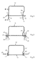
- a sheet 10 and a plate 12 just put together.
- Fig.1 are two edges 11 are present, while the hollow structures after Fig.4 has only one edge 11 with tabs 14, while the other edge 11 is angled and has a side surface 34 abuts the sheet 12.
- Edge structure 20 of this sheet is defined.
- the edge structure 20 can also be shaped differently than shown if this is is required for design reasons. In any case, should they serve for attachment to the edge 11 of the sheet 10.
- the edge 11 or the tabs 14 of the Edge 11 bent 90 degrees so that the tabs 14 parallel are arranged to the flat edge structure 20. That happens on both sides according to FIG. 2 or on only one side according to Figure 5.
- the tabs 14 angled under the edge structure 20 are then welded to the edge structure 20.
- One welding electrode 35 and a welding counter electrode 36 is pressed together and welding a tab 14 with the edge structure 20 e.g. point by point.
- the edge 11 lies flat on the sheet 12 and can be scored with this.
- FIGS. 2 and 5 are already stable in themselves. But they don't have theirs yet final shape, which has an optimal width or a aims for optimal stability at a given maximum width. Accordingly, the edge structure after welding together with the edge 11 or with its tabs 14 deformed antiparallel.
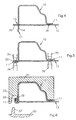
- Fig. 3 shows in principle the use of a deformation device by arrows 37.
- the arrows symbolize a deformation force of a not shown, but at known flanging device.
- the sheet edge 11 and the After the shaping, the edge structure 20 lies on the outside as a package the sheet 10 and consequently extend in the direction the arrows 37 only as far as necessary, namely the added Sheet thicknesses accordingly.
- Fig.3 is shown on the right that the bent Edge structure 20 with the angled tabs 14 of the sheet edge 11 is arranged in a recess 38 of the sheet 10, already with the U-shaped configuration of the plate 10 was produced at the same time.
- the recess 38 is a vertical one channel or recess running through to the display level, which is designed so that the outer surface the bent edge structure 20 with the adjacent outer surface 10 'of the deformed sheet 10 is flush.
- Fig.6 lets the manufacture of the antiparallel to the neighboring Wall of the sheet 10 deformation using a Detect trim channel 33.
- the trim channel 33 is in a die 31 introduced, which pre-shaped the entire V-like first Sheet 10 surrounds the outside and at the same time that shown in Figure 4 Forming this sheet 10 may have served.
- the trim channel 33 is now arranged so that the die 31st forms a trim projection 39 which rests on the outside of the sheet 10 and has a predetermined thickness.
- a male part 32 cooperates, which has a projection of deformation 32 'has.
- this deformation projection 32 ' can the edge structure 20 with the tabs connected to them 14 of the edge 11 from the position shown in Figure 5 are pressed into the position shown in FIG.
- the deformation takes place so that the edge structure 20 and the edge 11 of the adjacent sheet metal area of the Sheet 10 are assigned practically anti-parallel. Indeed here is a due to the thickness of the trim projection 39 Clearance available. This distance can perform functions on components take over, for which the hollow structure shown Fig.6 is used.
- the edge structure 20 can for example be used as fasteners.
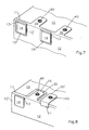
- Fig. 7 shows tabs 30 of the sheet 12 which are also angled are and rest on the outer surface of the sheet 10. They do not lie in bends and therefore jump vertically to sheet 10 before.
- the welding spots 40 shown mark their firm connection with the sheet 10.
- the arrangement the tabs 30 is such that they are in the Alternate the direction of the slot 13 with the tabs 14. This is in the sense of a symmetrization of the shown Edge formation advantageous. The result is an even one Stress distribution over the length of the edge.
- FIG 8 shows a further embodiment of a tab 30 ', which is welded to the sheet 10, e.g. with a weld spot 40.
- the tab 30 ' is not an integral part of the sheet 12, but overlaps this form-fitting.
- the tab 30 ' has a holding edge 41 which serves as an angle the tab 30 'is formed and the plate 12' also holds on the sheet 10.
- Such tabs 30 ' are special for subsequent or additional stiffening of the connection advantageous, especially for in the plane of the sheet 10 occurring burdens.
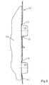
- 10a, 11a relate to welded connections with two sheets 10, 12, of which the sheet 12 provided with push-through slots 13 in the manner described above is.
- Several tabs 42 only one of each is shown jumping from an edge 11 of the first Sheet 10 in front and are inserted through the through slots 13 and also so anti-parallel to the first sheet 10 bent back to include edge structure 20, from the second sheet 12 between the slot 13 and the edge of which is formed.
- the edge structure is above all by the distance of the slot 13 to the sheet edge certainly.
- the tab 42 is welded to the first sheet 10.
- the welding point is designated 40. It takes place spot welding instead. Taking into account that several similarly designed tabs 42 are present, so results that only a single row of spot welds 40 is required is around the corner connection shown in FIGS. 10a, 11a to produce the two sheets 10, 12 with several tabs 42.
- 10a to 11b show that the distance the through slots 13 from the edge structure or from the parallel edge of the sheet 12 is different. It lies that the plate 10 in the area of the contact of the tab 42nd is provided with an offset 15, as in relation to FIG the tab 30 shown there has been described. Accordingly, the offset 43 according to FIGS. 11a, 11b may be larger than the offset 43 of FIGS. 10a, 10b.
- the bending area 44 can, however, be kept narrower, if the edge structure 20 in the region of the bent tabs 42 are left out. Such recesses are shown in FIGS. 10b, 11b 45 shown. The tab 42 can then in the area the recess 45 are deformed or the tab 42 can be kept shorter from the outset because the Area 44 is narrower. 10b, 11b, that the tabs 42 in sheet metal provided with recesses 45 12 can engage in these recesses 45, like that 10a, 11a can be seen.
- FIGS. 10a to 11b are designed so that the second sheet 12 in its the edge area having through-slots 13 only are positively included. A welding of both sheets 10.12 to each other does not take place. It is therefore advisable that the welded joint with differently designed welded joints is combined. For example, it is conceivable that the welds of Fig.10a to 11b with Alternate welding connections of Fig. 3.
Landscapes
- Engineering & Computer Science (AREA)
- Mechanical Engineering (AREA)
- General Engineering & Computer Science (AREA)
- Aviation & Aerospace Engineering (AREA)
- Transportation (AREA)
- Connection Of Plates (AREA)
- Lining Or Joining Of Plastics Or The Like (AREA)
- Chairs For Special Purposes, Such As Reclining Chairs (AREA)
Abstract
Description
- Fig.1
- einen Querschnitt durch zwei zusammengesteckte Bleche als Darstellung eines ersten Verfahrensschritts,
- Fig.2
- einen weiteren, auf die Bleche der Fig.1 angewendeten Verfahrensschritt des Schweißens nach einer vorhergegangenen Verformung des ersten Blechs,
- Fig.3
- eine weitere Verformung der Struktur der Fig.2 zu einer endgültigen Struktur, die als Holm einer Sitzrücklehne eines Kraftfahrzeugs angesehen werden kann,
- Fig.4-6
- den Fig.1 bis Fig.3 ähnliche Verfahrensschritte an einer etwas anderen Struktur unter Anwendung abweichender Verformungsmittel im dritten Verfahrensschritt,
- Fig.7
- eine perspektivische Darstellung einer Kantenstruktur zweier Bleche,
- Fig.8
- eine der Fig.7 entsprechende perspektivische Darstellung zweier Bleche mit abweichender Kantenausbildung,
- Fig.9
- den Schnitt IX-IX durch Fig.1 mit zusätzlich dargestellter Kröpfung des zweiten Blechs,
- Fig.10a, 11a
- einander ähnliche perspektivische Teilansichten einer Kantenstruktur zweier Bleche, und
- Fig.10b, 11b
- Schnitte A-A und B-B durch die Darstellungen der Fig.10a, 11b.
Claims (18)
- Schweißverbindung mit zwei Blechen, insbesondere mit zwei Blechen einer Sitzrücklehne, insbesondere eines Kraftfahrzeugs, mit einem ersten Blech (10), das eine abgewinkelte Blechkante (11) hat, die an einer Randstruktur (20) eines zweiten Blechs (12) anliegt und dort verschweißt ist, dadurch gekennzeichnet, daß das zweite Blech (12) mit einer vorbestimmten Anzahl von Durchsteckschlitzen (13) versehen ist, und daß das erste Blech (10) an seiner abgewinkelten Blechkante (11) durch die Durchsteckschlitze (13) hindurchgesteckte und unter die Randstruktur (20) abgewinkelte Laschen (14) hat, die nach ihrem Verschweißen mit der Randstruktur (20) gemeinsam mit dieser dem ersten Blech (10) praktisch antiparallel verformt sind.
- Schweißverbindung nach Anspruch 1, dadurch gekennzeichnet, daß die Randstruktur (20) eine ebene Blechkante ist.
- Schweißverbindung nach Anspruch 1 oder 2, dadurch gekennzeichnet, daß die verformte Randstruktur (20) an dem ersten Blech (10) praktisch anliegt.
- Schweißverbindung nach Anspruch 1 oder 2, dadurch gekennzeichnet, daß die Randstruktur (20) mit Abstand vom ersten Blech (10) antiparallel angeordnet ist.
- Schweißverbindung mit zwei Blechen, insbesondere mit zwei Blechen einer Sitzrücklehne, insbesondere eines Kraftfahrzeugs, mit einem ersten Blech (10), das eine abgewinkelte Blechkante (11) hat, die an einem eine Randstruktur (20) aufweisenden zweiten Blech (12) anliegt und in einem Anlagebereich verschweißt ist, dadurch gekennzeichnet, daß das zweite Blech (12) mit einer vorbestimmten Anzahl von Durchsteckschlitzen (13) versehen ist, und daß das erste Blech (10) an seiner abgewinkelten Blechkante (11) durch die Durchsteckschlitze (13) hindurchgesteckte und abgewinkelte Laschen (14) hat, die an einer dem ersten Blech (10) abgewendeten Blechfläche (12') des zweiten Blechs (12) und der Randstruktur (20) abgewendet verschweißt sind, und daß am zweiten Blech (12) eine Kante und/oder Laschen (30,30') angreifen, die am ersten Blech (10) abgewinkelt anliegt/anliegen und damit verschweißt ist/sind.
- Schweißverbindung nach Anspruch 5, dadurch gekennzeichnet, daß Laschen (14) des ersten Blechs (10) und am zweiten Blech (12) angreifende Laschen (30) in der Flucht der Durchsteckschlitze (13) einander abwechseln.
- Schweißverbindung nach Anspruch 5 oder 6, dadurch gekennzeichnet, daß am zweiten Blech (12) angreifende Laschen (30') das zweite Blech (12) querformschlüssig umklammern.
- Schweißverbindung mit zwei Blechen, insbesondere mit zwei Blechen einer Sitzrücklehne, insbesondere eines Kraftfahrzeugs, mit einem ersten Blech (10), das eine abgewinkelte Blechkante (11) hat, die eine Randstruktur (20) eines zweiten Bleches (12) umfaßt, und das Schweißstellen (40) aufweist, dadurch gekennzeichnet, daß das zweite Blech (12) mit einer vorbestimmten Anzahl von Durchsteckschlitzen (13) versehen ist, und daß das erste Blech (10) an seiner abgewinkelten Blechkante (11) durch die Durchsteckschlitze (13) hindurchgesteckte und abgewinkelte Laschen (42) hat, die um die Randstruktur (20) herumgebogen und mit dem ersten Blech (10) an dessen Schweißstellen (40) verschweißt sind.
- Schweißverbindung nach Anspruch 8, dadurch gekennzeichnet, daß die um die Randstruktur (20) herumgebogenen Laschen (42) des ersten Bleches (10) im Bereich der Schweißstellen (40) parallel zum ersten Blech (10) abgekröpft sind.
- Schweißverbindung nach Anspruch 8 oder 9, dadurch gekennzeichnet, daß die Randstruktur (20) im Bereich der herumgebogenen Laschen (42) ausgespart sind.
- Schweißverbindung nach einem oder mehreren der Ansprüche 1 bis 10, dadurch gekennzeichnet, daß das erste Blech (10) in einem Winkel zum zweiten Blech (12) angeordnet ist.
- Schweißverbindung nach einem oder mehreren der Ansprüche 1 bis 11, dadurch gekennzeichnet, daß das zweite Blech (12) mit dem ersten Blech (10) eine im Querschnitt geschlossene hohle Struktur bildet.
- Schweißverbindung nach einem oder mehreren der Ansprüche 1 bis 12, dadurch gekennzeichnet, daß die beiden Bleche (10,12) in Kantenbereichen der von ihnen gebildeten hohlen Struktur verschweißt sind.
- Schweißverbindung nach einem oder mehreren der Ansprüche 1 bis 13, dadurch gekennzeichnet, daß das zweite Blech (12) im Bereich seiner Durchsteckschlitze (13) zum ersten Blech (10) hin abgekröpft ist und die abgewinkelten Laschen (14) des ersten Blechs (10) in Abkröpfungen (15) des zweiten Blechs (12) mit diesem bündig angeordnet sind.
- Schweißverbindung nach einem oder mehreren der Ansprüche 1 bis 14, dadurch gekennzeichnet, daß das erste Blech (10) im Bereich von Kanten und/oder Laschen (30) zum zweiten Blech (12) hin abgekröpft ist und die Kanten und/oder Laschen (30) in Abkröpfungen (15) des ersten Blechs (10) mit diesem bündig angeordnet sind.
- Verfahren zum Verbinden zweier hochbelastbarer Bleche, insbesondere zweier Bleche einer Sitzrücklehne, insbesondere eines Kraftfahrzeugs, bei dem ein erstes Blech (10) mit einer abgewinkelten Blechkante (11) an ein zweites Blech (12) angelegt und dort verschweißt wird, dadurch gekennzeichnet, daß als zweites Blech (12) ein solches mit einer vorbestimmten Anzahl von Durchsteckschlitzen (13) verwendet wird, und daß als erstes Blech (10) eines mit vorstehenden Laschen (14) verwendet wird, die durch die Durchsteckschlitze (13) hindurchgesteckt werden, wonach ein Abwinkeln der Blechkante (11) im Bereich der Laschen (14) erfolgt, die danach an einer dem ersten Blech (10) abgewendeten Randstruktur (20) des zweiten Blechs (12) verschweißt und gemeinsam mit dieser dem ersten Blech (10) praktisch antiparallel verformt werden.
- Verfahren nach Anspruch 16, dadurch gekennzeichnet, daß das Verformen der Laschen (14) mit der Randstruktur (20) mittels einer Bördeleinrichtung erfolgt.
- Verfahren nach Anspruch 16 oder 17, dadurch gekennzeichnet, daß das erste Blech (10) von einer Matrize (31) umfaßt wird, die einen Trim-Kanal (33) hat, in dem eine praktisch antiparallele Verformung der Laschen (14) mit der Randstruktur (20) mittels einer Patrize (32) erfolgt.
Applications Claiming Priority (2)
| Application Number | Priority Date | Filing Date | Title |
|---|---|---|---|
| DE10039070 | 2000-08-10 | ||
| DE10039070A DE10039070A1 (de) | 2000-08-10 | 2000-08-10 | Schweißverbindung mit zwei Blechen |
Publications (3)
| Publication Number | Publication Date |
|---|---|
| EP1180410A2 true EP1180410A2 (de) | 2002-02-20 |
| EP1180410A3 EP1180410A3 (de) | 2002-04-10 |
| EP1180410B1 EP1180410B1 (de) | 2005-01-26 |
Family
ID=7651988
Family Applications (1)
| Application Number | Title | Priority Date | Filing Date |
|---|---|---|---|
| EP20010119280 Expired - Lifetime EP1180410B1 (de) | 2000-08-10 | 2001-08-09 | Schweissverbindung mit zwei Blechen und Verfahren zu ihrer Herstellung |
Country Status (3)
| Country | Link |
|---|---|
| EP (1) | EP1180410B1 (de) |
| AT (1) | ATE287779T1 (de) |
| DE (2) | DE10039070A1 (de) |
Cited By (7)
| Publication number | Priority date | Publication date | Assignee | Title |
|---|---|---|---|---|
| EP1375309A1 (de) * | 2002-06-28 | 2004-01-02 | Audi Ag | Fahrzeug-Strukturbereich aus einem Trägerbauteil und zwei damit verbundenen, aneinander angrenzenden Blechbauteilen |
| WO2005070609A3 (de) * | 2004-01-27 | 2005-12-22 | Opel Adam Ag | Verfahren zum verbinden zweier oder mehrerer profilteile oder bleche wobei die profilteile oder bleche an einer oder mehreren verbindungsstellen mechanisch verbunden und pressverschweisst sind |
| WO2006040282A1 (de) * | 2004-10-08 | 2006-04-20 | Johnson Controls Gmbh | LASERGESCHWEIßTER RAHMEN EINES SITZES SOWIE RECLINER |
| WO2006055616A1 (en) * | 2004-11-18 | 2006-05-26 | Johnson Controls Technology Company | Seat frame system and method of manufacturing |
| WO2008040421A1 (de) | 2006-10-02 | 2008-04-10 | Johnson Controls Interiors Gmbh & Co. Kg | Mehrteiliges fahrzeugausstattungsteil und verbindungsverfahren |
| EP1972407A1 (de) * | 2007-03-22 | 2008-09-24 | Karosseriewerke Dresden GmbH | Verfahren zur Herstellung durch Laser- oder Elektronstrahlschweissen eines Verbundkörpers ; Lehnen- und/oder Sitzstruktur |
| US20100171356A1 (en) * | 2006-10-27 | 2010-07-08 | Johnson Control Technology Company | Structural element for a vehicle seat |
Families Citing this family (4)
| Publication number | Priority date | Publication date | Assignee | Title |
|---|---|---|---|---|
| DE102005044221B4 (de) * | 2005-09-15 | 2021-07-22 | Adient Luxembourg Holding S.À R.L. | Verstärktes Seitenteil der Tragstruktur eines Kraftfahrzeugsitzes |
| DE102007049752A1 (de) | 2007-03-21 | 2008-09-25 | Johnson Controls Gmbh | Montageverfahren zur Bildung einer Sitzstruktur eines Fahrzeugsitzes und Sitzstruktur |
| DE102007042169B4 (de) | 2007-09-05 | 2015-02-19 | Faurecia Autositze Gmbh | Strukturteil für einen Fahrzeugsitz sowie Verfahren zu dessen Herstellung |
| DE102009053631B4 (de) * | 2009-11-17 | 2021-10-07 | Bayerische Motoren Werke Aktiengesellschaft | Verfahren zum Positionieren und Halten zweier Bauteile |
Family Cites Families (11)
| Publication number | Priority date | Publication date | Assignee | Title |
|---|---|---|---|---|
| DE42537C (de) * | F. C. BELLINGER in Fulda | Verbindung von Blechen | ||
| US2185236A (en) * | 1938-12-29 | 1940-01-02 | American Can Co | Container |
| FR977920A (fr) * | 1948-12-21 | 1951-04-06 | Dispositif pour l'assemblage de tôles minces par agrafage | |
| NL99366C (de) * | 1956-05-26 | |||
| US3205050A (en) * | 1962-09-10 | 1965-09-07 | Titanium Metals Corp | Attachment of a leader to a metallic strip |
| GB980669A (en) * | 1963-07-26 | 1965-01-20 | American Light Gage Drum Corp | Improvements in shipping containers |
| GB2246289A (en) * | 1990-07-26 | 1992-01-29 | Autoliv Dev | A vehicle seat |
| FR2671002B1 (fr) * | 1990-12-27 | 1993-04-16 | Faure Bertrand Automobile | Perfectionnements aux cadres d'ossature pour dossiers de sieges et analogues et a leurs procedes et dispositifs de fabrication. |
| US5524406A (en) * | 1994-03-24 | 1996-06-11 | Atd Corporation | Insulating apparatus and method for attaching an insulating pad to a support |
| US5581953A (en) * | 1995-05-31 | 1996-12-10 | Ingersoll-Rand | Metal frame assembly |
| US5878940A (en) * | 1996-01-16 | 1999-03-09 | Deere & Company | Method of fabricating sheet metal structures by welding and structure formed thereby |
-
2000
- 2000-08-10 DE DE10039070A patent/DE10039070A1/de not_active Withdrawn
-
2001
- 2001-08-09 DE DE50105174T patent/DE50105174D1/de not_active Expired - Fee Related
- 2001-08-09 EP EP20010119280 patent/EP1180410B1/de not_active Expired - Lifetime
- 2001-08-09 AT AT01119280T patent/ATE287779T1/de not_active IP Right Cessation
Cited By (8)
| Publication number | Priority date | Publication date | Assignee | Title |
|---|---|---|---|---|
| EP1375309A1 (de) * | 2002-06-28 | 2004-01-02 | Audi Ag | Fahrzeug-Strukturbereich aus einem Trägerbauteil und zwei damit verbundenen, aneinander angrenzenden Blechbauteilen |
| WO2005070609A3 (de) * | 2004-01-27 | 2005-12-22 | Opel Adam Ag | Verfahren zum verbinden zweier oder mehrerer profilteile oder bleche wobei die profilteile oder bleche an einer oder mehreren verbindungsstellen mechanisch verbunden und pressverschweisst sind |
| WO2006040282A1 (de) * | 2004-10-08 | 2006-04-20 | Johnson Controls Gmbh | LASERGESCHWEIßTER RAHMEN EINES SITZES SOWIE RECLINER |
| WO2006055616A1 (en) * | 2004-11-18 | 2006-05-26 | Johnson Controls Technology Company | Seat frame system and method of manufacturing |
| WO2008040421A1 (de) | 2006-10-02 | 2008-04-10 | Johnson Controls Interiors Gmbh & Co. Kg | Mehrteiliges fahrzeugausstattungsteil und verbindungsverfahren |
| US20100171356A1 (en) * | 2006-10-27 | 2010-07-08 | Johnson Control Technology Company | Structural element for a vehicle seat |
| US9108554B2 (en) * | 2006-10-27 | 2015-08-18 | Johnson Controls Technology Company | Structural element for a vehicle seat |
| EP1972407A1 (de) * | 2007-03-22 | 2008-09-24 | Karosseriewerke Dresden GmbH | Verfahren zur Herstellung durch Laser- oder Elektronstrahlschweissen eines Verbundkörpers ; Lehnen- und/oder Sitzstruktur |
Also Published As
| Publication number | Publication date |
|---|---|
| ATE287779T1 (de) | 2005-02-15 |
| DE10039070A1 (de) | 2002-02-21 |
| EP1180410A3 (de) | 2002-04-10 |
| EP1180410B1 (de) | 2005-01-26 |
| DE50105174D1 (de) | 2005-03-03 |
Similar Documents
| Publication | Publication Date | Title |
|---|---|---|
| DE19733470C1 (de) | Vorzugsweise U-förmiger Profilträger, insbesondere Rahmenlängsträger, für einen Tragrahmen eines Nutzfahrzeuges und Verfahren zu seiner Herstellung | |
| DE4429438A1 (de) | Verfahren zum Formen eines Bauteils | |
| DE19820473B4 (de) | Verfahren und Vorrichtung zur Herstellung eines im Querschnitt abgekanteten und in Längsrichtung zumindest teilweise gebogenen Produktes | |
| WO2021048059A1 (de) | Instrumententafelträger für ein kraftfahrzeug | |
| EP1180410B1 (de) | Schweissverbindung mit zwei Blechen und Verfahren zu ihrer Herstellung | |
| CH663336A5 (de) | Kasten. | |
| DE102010054183A1 (de) | Blechanordnung und Verfahren zum Verschweißen zweier Blechteile | |
| DE102007042169B4 (de) | Strukturteil für einen Fahrzeugsitz sowie Verfahren zu dessen Herstellung | |
| DE4023393C2 (de) | ||
| EP1492694A1 (de) | Y-knotenstruktur eines tragrahmens für fahrzeuge | |
| DE202005001773U1 (de) | Lehnenrahmen für Kraftfahrzeugsitze | |
| EP2047924B1 (de) | Verfahren zur Herstellung einer Leitschranke | |
| DE19751513C2 (de) | Verfahren zur Herstellung einer Crash-Box, sowie Crash-Box | |
| DE19753653B4 (de) | Stahlblechtür | |
| DE69422567T2 (de) | Herstellungsverfahren für einen Farbwahlelektrode-Einbaurahmen für Kathodenstrahlröhre und Kathodenstrahlröhre mit einem derartigen Farbwahlelektrode-Einbaurahmen | |
| DE69404887T2 (de) | Verfahren zum Laserschweissen von tiefgezogene Werkstücke umlaufenden Blechflansche | |
| EP2724895B1 (de) | Stoßfängerquerträgerbaugruppe | |
| DE102009054557B4 (de) | Verfahren zum Verschweißen zweier Bauteile und Bauteilanordnung mit zwei Bauteilen | |
| EP4062003B1 (de) | Ankerschiene und verfahren zur herstellung einer ankerschiene | |
| DE19753103A1 (de) | Verfahren zum Verschweißen zweier plattenförmiger Werkstücke | |
| DE102019105536B4 (de) | Fügeverfahren sowie Halbzeug | |
| DE202022101691U1 (de) | Maschine zur Herstellung eines Isolators | |
| EP1127776A2 (de) | Anordnung eines tragenden Bauteils einer Fahrzeugkarosserie | |
| DE69203796T2 (de) | Verfahren zum Verbinden, durch Nieten, durch dieses Verfahren hergestellte Verbindung und Vorrichtung zum Herstellen. | |
| DE102004011252B3 (de) | Fahrzeugrahmen |
Legal Events
| Date | Code | Title | Description |
|---|---|---|---|
| PUAI | Public reference made under article 153(3) epc to a published international application that has entered the european phase |
Free format text: ORIGINAL CODE: 0009012 |
|
| AK | Designated contracting states |
Kind code of ref document: A2 Designated state(s): AT BE CH CY DE DK ES FI FR GB GR IE IT LI LU MC NL PT SE TR |
|
| AX | Request for extension of the european patent |
Free format text: AL;LT;LV;MK;RO;SI |
|
| PUAL | Search report despatched |
Free format text: ORIGINAL CODE: 0009013 |
|
| AK | Designated contracting states |
Kind code of ref document: A3 Designated state(s): AT BE CH CY DE DK ES FI FR GB GR IE IT LI LU MC NL PT SE TR |
|
| AX | Request for extension of the european patent |
Free format text: AL;LT;LV;MK;RO;SI |
|
| 17P | Request for examination filed |
Effective date: 20020828 |
|
| 17Q | First examination report despatched |
Effective date: 20021022 |
|
| AKX | Designation fees paid |
Free format text: AT BE CH CY DE DK ES FI FR GB GR IE IT LI LU MC NL PT SE TR |
|
| GRAP | Despatch of communication of intention to grant a patent |
Free format text: ORIGINAL CODE: EPIDOSNIGR1 |
|
| RTI1 | Title (correction) |
Free format text: WELDED JOINT OF TWO THIN SHEETS UND PROCESS FOR ITS MANUFACTURING |
|
| GRAA | (expected) grant |
Free format text: ORIGINAL CODE: 0009210 |
|
| GRAS | Grant fee paid |
Free format text: ORIGINAL CODE: EPIDOSNIGR3 |
|
| AK | Designated contracting states |
Kind code of ref document: B1 Designated state(s): AT BE CH CY DE DK ES FI FR GB GR IE IT LI LU MC NL PT SE TR |
|
| PG25 | Lapsed in a contracting state [announced via postgrant information from national office to epo] |
Ref country code: IT Free format text: LAPSE BECAUSE OF FAILURE TO SUBMIT A TRANSLATION OF THE DESCRIPTION OR TO PAY THE FEE WITHIN THE PRESCRIBED TIME-LIMIT;WARNING: LAPSES OF ITALIAN PATENTS WITH EFFECTIVE DATE BEFORE 2007 MAY HAVE OCCURRED AT ANY TIME BEFORE 2007. THE CORRECT EFFECTIVE DATE MAY BE DIFFERENT FROM THE ONE RECORDED. Effective date: 20050126 Ref country code: TR Free format text: LAPSE BECAUSE OF FAILURE TO SUBMIT A TRANSLATION OF THE DESCRIPTION OR TO PAY THE FEE WITHIN THE PRESCRIBED TIME-LIMIT Effective date: 20050126 Ref country code: NL Free format text: LAPSE BECAUSE OF FAILURE TO SUBMIT A TRANSLATION OF THE DESCRIPTION OR TO PAY THE FEE WITHIN THE PRESCRIBED TIME-LIMIT Effective date: 20050126 Ref country code: FI Free format text: LAPSE BECAUSE OF FAILURE TO SUBMIT A TRANSLATION OF THE DESCRIPTION OR TO PAY THE FEE WITHIN THE PRESCRIBED TIME-LIMIT Effective date: 20050126 Ref country code: IE Free format text: LAPSE BECAUSE OF FAILURE TO SUBMIT A TRANSLATION OF THE DESCRIPTION OR TO PAY THE FEE WITHIN THE PRESCRIBED TIME-LIMIT Effective date: 20050126 |
|
| REG | Reference to a national code |
Ref country code: IE Ref legal event code: FG4D Free format text: GERMAN Ref country code: GB Ref legal event code: FG4D Free format text: NOT ENGLISH |
|
| REG | Reference to a national code |
Ref country code: CH Ref legal event code: EP |
|
| REF | Corresponds to: |
Ref document number: 50105174 Country of ref document: DE Date of ref document: 20050303 Kind code of ref document: P |
|
| RAP2 | Party data changed (patent owner data changed or rights of a patent transferred) |
Owner name: ATL ENGINEERING GMBH |
|
| PG25 | Lapsed in a contracting state [announced via postgrant information from national office to epo] |
Ref country code: DK Free format text: LAPSE BECAUSE OF FAILURE TO SUBMIT A TRANSLATION OF THE DESCRIPTION OR TO PAY THE FEE WITHIN THE PRESCRIBED TIME-LIMIT Effective date: 20050426 Ref country code: SE Free format text: LAPSE BECAUSE OF FAILURE TO SUBMIT A TRANSLATION OF THE DESCRIPTION OR TO PAY THE FEE WITHIN THE PRESCRIBED TIME-LIMIT Effective date: 20050426 Ref country code: GR Free format text: LAPSE BECAUSE OF FAILURE TO SUBMIT A TRANSLATION OF THE DESCRIPTION OR TO PAY THE FEE WITHIN THE PRESCRIBED TIME-LIMIT Effective date: 20050426 |
|
| NLT2 | Nl: modifications (of names), taken from the european patent patent bulletin |
Owner name: ATL ENGINEERING GMBH |
|
| PG25 | Lapsed in a contracting state [announced via postgrant information from national office to epo] |
Ref country code: ES Free format text: LAPSE BECAUSE OF FAILURE TO SUBMIT A TRANSLATION OF THE DESCRIPTION OR TO PAY THE FEE WITHIN THE PRESCRIBED TIME-LIMIT Effective date: 20050507 |
|
| GBT | Gb: translation of ep patent filed (gb section 77(6)(a)/1977) |
Effective date: 20050509 |
|
| NLV1 | Nl: lapsed or annulled due to failure to fulfill the requirements of art. 29p and 29m of the patents act | ||
| PGFP | Annual fee paid to national office [announced via postgrant information from national office to epo] |
Ref country code: GB Payment date: 20050803 Year of fee payment: 5 |
|
| PG25 | Lapsed in a contracting state [announced via postgrant information from national office to epo] |
Ref country code: CY Free format text: LAPSE BECAUSE OF FAILURE TO SUBMIT A TRANSLATION OF THE DESCRIPTION OR TO PAY THE FEE WITHIN THE PRESCRIBED TIME-LIMIT Effective date: 20050809 Ref country code: AT Free format text: LAPSE BECAUSE OF NON-PAYMENT OF DUE FEES Effective date: 20050809 Ref country code: LU Free format text: LAPSE BECAUSE OF NON-PAYMENT OF DUE FEES Effective date: 20050809 |
|
| REG | Reference to a national code |
Ref country code: IE Ref legal event code: FD4D |
|
| PGFP | Annual fee paid to national office [announced via postgrant information from national office to epo] |
Ref country code: FR Payment date: 20050829 Year of fee payment: 5 |
|
| PG25 | Lapsed in a contracting state [announced via postgrant information from national office to epo] |
Ref country code: CH Free format text: LAPSE BECAUSE OF NON-PAYMENT OF DUE FEES Effective date: 20050831 Ref country code: BE Free format text: LAPSE BECAUSE OF NON-PAYMENT OF DUE FEES Effective date: 20050831 Ref country code: MC Free format text: LAPSE BECAUSE OF NON-PAYMENT OF DUE FEES Effective date: 20050831 Ref country code: LI Free format text: LAPSE BECAUSE OF NON-PAYMENT OF DUE FEES Effective date: 20050831 |
|
| PGFP | Annual fee paid to national office [announced via postgrant information from national office to epo] |
Ref country code: DE Payment date: 20051028 Year of fee payment: 5 |
|
| PLBE | No opposition filed within time limit |
Free format text: ORIGINAL CODE: 0009261 |
|
| STAA | Information on the status of an ep patent application or granted ep patent |
Free format text: STATUS: NO OPPOSITION FILED WITHIN TIME LIMIT |
|
| 26N | No opposition filed |
Effective date: 20051027 |
|
| ET | Fr: translation filed | ||
| REG | Reference to a national code |
Ref country code: CH Ref legal event code: PL |
|
| PG25 | Lapsed in a contracting state [announced via postgrant information from national office to epo] |
Ref country code: DE Free format text: LAPSE BECAUSE OF NON-PAYMENT OF DUE FEES Effective date: 20070301 |
|
| GBPC | Gb: european patent ceased through non-payment of renewal fee |
Effective date: 20060809 |
|
| REG | Reference to a national code |
Ref country code: FR Ref legal event code: ST Effective date: 20070430 |
|
| PG25 | Lapsed in a contracting state [announced via postgrant information from national office to epo] |
Ref country code: GB Free format text: LAPSE BECAUSE OF NON-PAYMENT OF DUE FEES Effective date: 20060809 |
|
| BERE | Be: lapsed |
Owner name: ATL ENGINEERING G.M.B.H. Effective date: 20050831 |
|
| PG25 | Lapsed in a contracting state [announced via postgrant information from national office to epo] |
Ref country code: PT Free format text: LAPSE BECAUSE OF NON-PAYMENT OF DUE FEES Effective date: 20050626 |
|
| PG25 | Lapsed in a contracting state [announced via postgrant information from national office to epo] |
Ref country code: FR Free format text: LAPSE BECAUSE OF NON-PAYMENT OF DUE FEES Effective date: 20060831 |