EP1182098A2 - Überrollschutzsystem - Google Patents
Überrollschutzsystem Download PDFInfo
- Publication number
- EP1182098A2 EP1182098A2 EP01111893A EP01111893A EP1182098A2 EP 1182098 A2 EP1182098 A2 EP 1182098A2 EP 01111893 A EP01111893 A EP 01111893A EP 01111893 A EP01111893 A EP 01111893A EP 1182098 A2 EP1182098 A2 EP 1182098A2
- Authority
- EP
- European Patent Office
- Prior art keywords
- spring
- protection system
- guide pin
- compression spring
- rollover protection
- Prior art date
- Legal status (The legal status is an assumption and is not a legal conclusion. Google has not performed a legal analysis and makes no representation as to the accuracy of the status listed.)
- Granted
Links
Images


Classifications
-
- B—PERFORMING OPERATIONS; TRANSPORTING
- B60—VEHICLES IN GENERAL
- B60R—VEHICLES, VEHICLE FITTINGS, OR VEHICLE PARTS, NOT OTHERWISE PROVIDED FOR
- B60R21/00—Arrangements or fittings on vehicles for protecting or preventing injuries to occupants or pedestrians in case of accidents or other traffic risks
- B60R21/02—Occupant safety arrangements or fittings, e.g. crash pads
- B60R21/13—Roll-over protection
Definitions
- Rollover protection systems of this type serve to protect the occupants in Motor vehicles without a protective roof, typically in convertibles or Sports cars.
- the holding device typically has one on the rollover body attached retaining member, which is in releasable mechanical connection with a Trigger link on a sensor-controlled trigger system that typically by a trigger magnet, the so-called crash magnet, or is formed by a pyrotechnic trigger member.
- the Locking device typically consists of a pivotable Articulated detent with tooth segments and a fixed tooth bar or the like, one element with the roll bar and the other is connected to the vehicle.
- Such a cassette construction of a roll bar protection system shows for example DE 43 42 400 A 1.
- DE 197 81 833 T 1 also shows this Cassette construction.
- the above known rollover protection system has, in particular, a housing in the form of a U-shaped cassette which is open on one side, with two side walls, each of which has an outwardly angled section on the open side of the cassette for fastening the cassette in a vehicle-fixed manner, to which a base plate also remains is attached, and which are finally connected to each other at the front via a cover wall.
- the rollover protection system also has a U-shaped roll bar as a rollover body, consisting of a curved section and two parallel leg tubes, each with a closed jacket surface, and the open ends of which are connected to one another via a crossbar-like, stiffening connecting element.
- the system also has two standpipes, which are attached at one end to the bottom of the housing and each contain a drive compression spring for the sole drive of the roll bar, which are each coaxially encompassed by a leg tube and also have a closed jacket surface and one at the upper end of the housing Guide block attached flat to the side walls of the cassette, which has guide openings for additional external guidance of the leg tubes.
- whirring noises occur during driving can, which are sometimes perceived as disturbing. These whirring noises are caused by an interaction between the drive pressure spring and the surrounding, from the respective leg tube of the roll bar Covered standpipe generated because the distance between the envelope of the Drive compression spring and the standpipe is not even and also from Space constraints is relatively small due to the design.
- the invention is therefore based on the object, these whirring noises to eliminate relatively simple means constructively.
- the spreading centering arms result in a concentric guidance of the Drive compression spring in the pipe surrounding it, be it the standpipe or directly the leg tube, and thus ensure an even distance between the envelope of the drive compression spring and that surrounding it Pipe. This advantageously prevents whirring noises, at least be significantly reduced.
- a particularly effective centering can be achieved if according to a Embodiment of the invention the spreading centering arms yielding elastically are formed, and when the centering arms at the same level of Spring guide bolts are arranged circumferentially at equal intervals.
- a weight-favorable construction of the spring guide pin can be achieve if the spring guide pin has a cross-shaped cross section and has a tapered head, the head thus designed a Penetration of other hollow components is easier.
- the operative connection of the drive pressure spring with the spring guide pin and the rollover body can be according to a development of the invention constructively advantageous if the set of spreading centering arms is attached to one end of the spring guide pin and a shoulder for has the support of one end of the drive compression spring, with her other end is centered in a spring cup, which in turn with a stop of the rollover body is in driving operative connection.
- the production can also be made so that the Spring guide pin with its centering arms made of several components is constructed, preferably that the spring guide pin is a metallic Extruded section is on which a conical forming the centering arms Plastic part is inserted.
- the spring guide pin according to the invention is preferably used in a rollover body in the form of a U-shaped roll bar with a curved base part and two parallel leg tubes, in the bottom part of the cassette housing two spring guide bolts corresponding to the Bow tube width are anchored spaced, each a drive compression spring for extending the roll bar into its upper, protective Take up position directly from the leg tubes of the roll bar are included, given a uniform distance by the spread centering arms.
- This construction advantageously allows the leg tubes to be omitted leading standpipes.
- FIG. 1 shows the basic structure in an isometric representation a rollover protection system, with parts broken away in which the Spring guide bolts designed according to the invention are preferably used Find.
- Figure 1 the extended state of the rollover body shown.
- This rollover protection system initially has a U-shaped roll bar 1 on, which is composed of three tubes 2, 3, 4. Thereby forms the Base leg of the roll bar 1 essentially a curved tube 2, which at its ends with two leg tubes 3, 4 by welding or other suitable connection types is rigidly connected.
- a rollover body which consists of a one-piece profile body is formed.
- leg tubes 3, 4 are by means of a cross member 5 rigidly connected to each other.
- the traverse 5 as Profile body formed with a predetermined height
- the holes 6 for Includes the leg tubes 3, 4, in which they are attached.
- the roll bar 1 is with its two leg tubes 3, 4, one have a closed outer surface, in a cassette-like housing 7 recorded and held retractable or retractable therein.
- This case shows two side parts 8, 9, which are formed by a U-shaped profile body are, which are preferably made of metal, in particular steel.
- This Side profiles 8, 9 are below a bottom plate part 10 and above one Guide block 11 connected together, e.g. by rivets, screws, Welding or the like.
- the even distance between the associated Compression spring 14, 15 and the associated leg tube 3, 4 secure what is has an advantageous noise-reducing effect.
- the two side profiles 8, 9 are useful, at least on a front side the cassette, connected to a cover plate that is practical, however not necessarily over the entire height of the cassette (not ) Shown.
- the guide block 11 has two guide bores 18, 19 which the Support lateral surface of the leg tubes 3, 4 laterally and a very wide tolerated guidance for the along the guide bores 18, 19th moving leg tubes 3, 4 offer.
- the curved tube 2 facing end of the guide bores 18, 19 is expediently a radial Countersink or annular groove created, which in a known manner receives annular, radially elastic guide bushing (not shown), whereby the radial play of the stirrup leg tubes 3, 4 in the Guide bores 18, 19 is compensated.
- the Leg tubes also provided an inner guide, which is mentioned by the housing-fixed spring guide bolts or standpipes is guaranteed.
- a retaining lug 20 is attached to the cross member 5, preferably molded in one piece, which can be swiveled into active engagement with one in the base part articulated, prestressed clockwise by means of a spring 22a Holding pawl 21 can be brought.
- the retaining pawl 21 With the roll bar 1 lowered, and therefore also when the crossmember 5 is lowered, the retaining pawl 21 includes the retaining lug 20 and keeps the roll bar in this rest position.
- a spacer 23, each in the side profiles 8, 9 is fixed, limits the displaceability of the Traverse 5 down and thus specifies the rest position. Furthermore, the Spacer 23 when screwing the cassette in the vehicle Deformation of the side profiles avoided.
- a sensor-controlled trigger system 22 is also fixed on the base part 10 attached, preferably by a pyrotechnic trigger element formed, the safer than a conventional trigger magnet, the relatively high Impact of the pawl 21 on the retaining lug 20 can overcome.
- a locking pin 24 is fastened to the cross member 5 in a manner known per se, the in the upper position with a locking pawl 25 which in Guide block 11 is pivoted about the shaft 26, locking in Active intervention can be brought to an unwanted pressing in the roll bar prevent in an extended position.
- This lock is in the DE 43 42 400 A1 cited at the beginning.
- the cassette housing is preferably attached to the vehicle by fastening the floor panel 10 to the vehicle floor. Is also one Attachment to the seat frame possible, if usual on the side profiles, after outside angled mounting strips are attached or molded.
- the cassette housing does not necessarily have to consist of separate side profiles 8, 9 be composed. It can also be used with a U-shaped profile part Connecting legs as a cover plate and the U-legs as side walls are additionally folded to form the side profile at the free end, be formed.
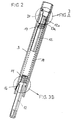
- FIGS. 2 and 3 show the one designed according to the invention Spring guide bolt shown in more detail, with respect to Fig. 1, the left Spring guide pin 12 with the drive spring 14 surrounding it and the this in turn surrounding leg tube 3 is shown.
- the Spring guide pin 12 has a cross-shaped cross section (Fig. 3 B) and a tapered headboard 12 a. He also shows a set of spread, resilient centering arms 16 on at regular intervals are arranged all around. At the transition point to the elongated one Part of the spring guide pin 12 is an approach, a shoulder 16 a formed on which the lower end of the drive compression spring 14 is supported.
- the upper end of the drive compression spring 14 is supported in a cylindrical Spring cup 27, which is received in the leg tube 3, and the one has a tapering circumferential edge portion 27 a in which the upper end of the drive spring 14 is centered.
- the leg tube 3 has two opposite stops 28 as an axial one Stop for the spring cup 27, which with its upper edge due to Drive compression spring 14 abuts these stops 28.
- the stops 28 can, as shown, be formed by blind rivets. She can also by embossing in the leg tube 3 or comparative means be educated.
- the lower position of the roll bar with The spring pot serves to show the tensioned drive pressure spring, to show it 27 on the one hand the centering of the drive compression spring 14 in the lower part is centered by the centering arms 16 and the spring guide pin 12 and on the other hand the active intervention with the leg tube during the implementation the spring force in a raising movement of the roll bar. That is because Holding device 20, 21 (Fig. 1) triggered, then presses the drive compression spring 14 about the spring cup 27 and the axial stops 28 that Leg tube 3 and thus the roll bar 1 upwards, the Spring guide pin 12 remains stationary.
- the spring guide pin 12 is preferably a plastic injection molded part which the flexible spreading arms 16 are integrally formed. He can too be made up of several pieces and also from different materials, for example with a metallic rod from an extruded profile an inserted plastic cone as tip 12 and a lower one Plastic segment with a tapered split jacket to realize the flexible spreading arms 16.
- the materials used should be good Have sliding properties, preferably self-lubricating, e.g. the Plastic POM.
- the spring cup 27 is preferred axially symmetrical to prevent incorrect installation with asymmetrical Avoid design, i.e. the edge portion 27 a is at both ends equally designed and can therefore function on both sides (stop, Exercise the compression spring).
- the spring guide pin is fixed to the bottom of the Cassette housing attached.
- the execution can, as in the case of the beginning cited EP 0 623 492 B1, can also be such that the Spring guide bolt firmly with the upper end of the drive pressure spring connected, i.e. with this extends (flying bolt).
- the arrangement of the Components (spring cup, spreader arms) are then inverted.
Landscapes
- Engineering & Computer Science (AREA)
- Mechanical Engineering (AREA)
- Cooling, Air Intake And Gas Exhaust, And Fuel Tank Arrangements In Propulsion Units (AREA)
- Refuge Islands, Traffic Blockers, Or Guard Fence (AREA)
- Springs (AREA)
- Fittings On The Vehicle Exterior For Carrying Loads, And Devices For Holding Or Mounting Articles (AREA)
- Body Structure For Vehicles (AREA)
Abstract
Description
- einem fahrzeugfest anbringbaren kassettenartigen Gehäuse,
- einem im Gehäuse geführten Überrollkörper, der im Normalzustand gegen die Kraft von mindestens einer vorgespannten, von einem Rohr umgebenen Antriebs-Druckfeder durch eine Haltevorrichtung in einer unteren eingefahrenen Ruhelage haltbar ist, und unter Lösen der Haltevorrichtung durch die Federkraft der Antriebs-Druckfeder in eine obere, schützende, und dort verriegelbare Stellung bringbar ist, und
- einem Federführungsbolzen, der von der Antriebs-Druckfeder umfaßt ist.
Das System weist ferner zwei mit einem Ende am Gehäuseboden angebrachte, in Innern jeweils eine Antriebs-Druckfeder für den alleinigen Antrieb des Überrollbügels aufnehmende, Standrohre, die jeweils von einem Schenkelrohr koaxial umgriffen sind und ebenfalls eine geschlossene Mantelfläche aufweisen sowie einen am oberen Ende des Gehäuses flächig an den Seitenwänden der Kassette angebrachten Führungsblock auf, der Führungsöffnungen zur zusätzlichen äußeren Führung der Schenkelrohre besitzt.
- einem fahrzeugfest anbringbaren kassettenartigen Gehäuse,
- einem im Gehäuse geführten Überrollkörper, der im Normalzustand gegen die Kraft von mindestens einer vorgespannten, von einem Rohr umgebenen Antriebs-Druckfeder durch eine Haltevorrichtung in einer unteren eingefahrenen Ruhelage haltbar ist, und unter Lösen der Haltevorrichtung durch die Federkraft der Antriebs-Druckfeder in eine obere, schützende, und dort verriegelbare Stellung bringbar ist, und
- einem Federführungsbolzen, der von der Antriebs-Druckfeder umfaßt ist,
- Figur 1
- in einer isometrischen Darstellung den Gesamtaufbau eines Überrollbügelsystems, bei dem die Erfindung bevorzugt Anwendung findet, mit einem Kassettengehäuse, das U-förmige Seitenprofile aufweist, an denen ein Führungsblock für die Schenkelrohre eines U-förmigen Überrollbügels fest angebracht und in denen eine, die Schenkelrohre des Überrollbügels verbindende Traverse geführt ist,
- Fig. 2
- in einer Längsschnitt-Darstellung den Federführungsbolzen der Konstruktion nach Fig. 1, in Verbindung mit der zugehörigen Antriebs-Druckfeder und dem Schenkelrohr des Überrollbügels,
- Fig. 3
- in zwei Figurenteilen A, B ausschnittsweise in vergrößerten Darstellungen den Kopf- und den Fußteil des Federführungsbolzens mit Abstützung der Antriebs-Druckfeder an der Wurzel der Zentrierarme und in einem Federtopf, der in antreibender Wirkverbindung mit dem Schenkelrohr steht.
Claims (12)
- Überrollschutzsystem, mitdadurch gekennzeichnet, daß an dem Federführungsbolzen (12, 13) mindestens ein Satz gespreizter Zentrierarme (16, 17) angebracht ist, die einen gleichmäßigen Abstand der Antriebs-Druckfeder (14, 15) zu dem sie umgebenden Rohr (3, 4) sichern.einem fahrzeugfest anbringbaren kassettenartigen Gehäuse (7),einem im Gehäuse (7) geführten Überrollkörper (1), der im Normalzustand gegen die Kraft von mindestens einer vorgespannten, von einem Rohr umgebenen Antriebs-Druckfeder (14, 15) durch eine Haltevorrichtung (20, 21) in einer unteren eingefahrenen Ruhelage haltbar ist, und unter Lösen der Haltevorrichtung durch die Federkraft der Antriebs-Druckfeder (14, 15) in eine obere, schützende, und dort verriegelbare Stellung bringbar ist, undeinem Federführungsbolzen (12, 13), der von der Antriebs-Druckfeder umfaßt ist,
- Überrollschutzsystem nach Anspruch 1, dadurch gekennzeichnet, daß die gespreizten Zentrierarme (16, 17) elastisch nachgebend ausgebildet sind.
- Überrollschutzsystem nach Anspruch 1 oder 2, dadurch gekennzeichnet, daß die Zentrierarme (16, 17) auf gleicher Höhe des Federführungsbolzens (12, 13) in gleichen Abständen umlaufend angeordnet sind.
- Überrollschutzsystem nach einem der Ansprüche 1 bis 3, dadurch gekennzeichnet, daß der Federführungsbolzen (12, 13) einen kreuzfrömigen Querschnitt und einen spitz zulaufenden Kopf (12 a) besitzt.
- Überrollschutzsystem nach einem der Ansprüche 1 bis 4, dadurch gekennzeichnet, daß der Satz gespreizter Zentrierarme (16, 17) am einen Ende des Federführungsbolzens (12, 13) angebracht ist und eine Schulter (16 a) für die Abstützung des einen Endes der Antriebs-Druckfeder (14, 15) besitzt, die mit ihrem anderen Ende in einem Federtopf (27) zentriert gelagert ist, der wiederum mit einem Anschlag (28) des Überrollkörpers (1) in antreibender Wirkverbindung steht.
- Überrollschutzsystem nach einem der Ansprüche 1 bis 5, dadurch gekennzeichnet, daß der Federführungsbolzen (12, 13) ein Kunststoff-Spritzgießteil ist, an dem die Zentrierarme (16, 17) einstückig angespritzt sind.
- Überrollschutzsystem nach einem der Ansprüche 1 bis 5, dadurch gekennzeichnet, daß der Federführungsbolzen (12, 13) mit seinen Zentrierarmen (16, 17) mehrstückig aus Komponenten aufgebaut ist.
- Überrollschutzsystem nach Anspruch 7, dadurch gekennzeichnet, daß der Federführungsbolzen (12, 13) ein metallisches Strangpreßprofilteil ist, an dem ein die Zentrierarme bildendes, kegeliges Kunststoffteil eingesetzt ist.
- Überrollschutzsystem nach einem der Ansprüche 1 bis 8, mit einem Überrollkörper in Form eines U-förmigen Überrollbügels (1) mit einem gebogenen Basisteil (2) und zwei parallelen Schenkelrohren (3, 4), dadurch gekennzeichnet, daß im Bodenteil (10) des Kassettengehäuses (7) zwei Federführungsbolzen (12, 13) entsprechend der Bügelrohrbreite beabstandet verankert sind, die jeweils eine Antriebs-Druckfeder (14, 15) für das Ausfahren des Überrollbügels (1) in seine obere, schützende Stellung aufnehmen, welche direkt von den Schenkelrohren (3, 4) des Überrollbügels (1) umfaßt sind, unter Vorgabe eines gleichförmigen Abstandes durch die gespreizten Zentrierarme (16, 17).
- Überrollschutzsystem nach einem der Ansprüche 5 bis 9, dadurch gekennzeichnet, daß der Federtopf (27) so geformt ist, daß er sowohl für die Druckfeder (14) als auch für den Federführungsbolzen (12) eine Zentrierfunktion in dem ihn umgebenden Rohr (3, 4) gewährleistet.
- Überrollschutzsystem nach Anspruch 10, dadurch gekennzeichnet, daß er rotationssymmetrisch ausgebildet ist und an beiden Stirnseiten einen gleich ausgebildeten, sich im Durchmesser verjüngenden Randabschnitt (27 a) besitzt.
- Überrollschutzsystem nach Anspruch 10 oder 11, dadurch gekennzeichnet, daß der Federtopf (27) aus Metall oder Kunststoff hergestellt ist, die gute Gleiteigenschaften aufweisen, vorzugsweise selbstschmierend sind.
Applications Claiming Priority (2)
| Application Number | Priority Date | Filing Date | Title |
|---|---|---|---|
| DE10040642 | 2000-08-19 | ||
| DE2000140642 DE10040642C1 (de) | 2000-08-19 | 2000-08-19 | Überrollschutzsystem |
Publications (3)
| Publication Number | Publication Date |
|---|---|
| EP1182098A2 true EP1182098A2 (de) | 2002-02-27 |
| EP1182098A3 EP1182098A3 (de) | 2004-07-28 |
| EP1182098B1 EP1182098B1 (de) | 2006-03-15 |
Family
ID=7653025
Family Applications (1)
| Application Number | Title | Priority Date | Filing Date |
|---|---|---|---|
| EP20010111893 Expired - Lifetime EP1182098B1 (de) | 2000-08-19 | 2001-05-17 | Überrollschutzsystem |
Country Status (3)
| Country | Link |
|---|---|
| EP (1) | EP1182098B1 (de) |
| DE (2) | DE10040642C1 (de) |
| ES (1) | ES2262573T3 (de) |
Cited By (1)
| Publication number | Priority date | Publication date | Assignee | Title |
|---|---|---|---|---|
| EP1705073A2 (de) | 2005-03-23 | 2006-09-27 | Bayerische Motorenwerke Aktiengesellschaft | Überrollschutzsystem |
Families Citing this family (23)
| Publication number | Priority date | Publication date | Assignee | Title |
|---|---|---|---|---|
| DE10219447B4 (de) * | 2002-05-02 | 2005-10-20 | Ise Gmbh | Überrollschutzsystem für Kraftfahrzeuge mit einer selbsthaltenden Entriegelungseinrichtung |
| DE102004035015B3 (de) | 2004-07-20 | 2005-12-08 | Ise Innomotive Systems Europe Gmbh | Überrollschutzsystem für Kraftfahrzeuge mit versenkbarem Dach |
| DE102005010186B3 (de) * | 2005-03-05 | 2006-04-13 | Ise Innomotive Systems Europe Gmbh | Überrollschutzsystem für Kraftfahrzeuge mit einem federbetätigt ausfahrbaren Überrollkörper |
| DE102005016371B3 (de) * | 2005-04-09 | 2006-06-14 | Ise Innomotive Systems Europe Gmbh | Überrollschutzsystem für Kraftfahrzeuge mit einem ausfahrbaren säulenförmigen Überrollkörper |
| DE102005047274B3 (de) * | 2005-10-01 | 2007-01-18 | Ise Innomotive Systems Europe Gmbh | Überrollschutzsystem für Kraftfahrzeuge mit einem aufstellbaren Überrollkörper |
| DE102005051143B3 (de) * | 2005-10-26 | 2006-10-26 | Ise Innomotive Systems Europe Gmbh | Überrollschutzsystem für Kraftfahrzeuge mit einer selbsthaltenden Entriegelungseinrichtung |
| DE102005059910B3 (de) | 2005-12-15 | 2007-04-12 | Automotive Group Ise Innomotive Systems Europe Gmbh | Überrollschutzsystem für Kraftfahrzeuge mit einem faltbaren Überrollbügel |
| DE102006001579B3 (de) * | 2006-01-12 | 2007-03-01 | Ise Innomotive Systems Europe Gmbh | Überrollschutzsystem für Kraftfahrzeuge mit einem aktiv aufstellbaren Überrollbügel |
| DE102006002941A1 (de) * | 2006-01-21 | 2007-08-02 | Automotive Group Ise Innomotive Systems Europe Gmbh | Überrollschutzsystem für Kraftfahrzeuge mit einem Überrollbügel |
| DE102006006659B3 (de) * | 2006-02-14 | 2007-06-21 | Automotive Group Ise Innomotive Systems Europe Gmbh | Überrollschutzsystem für Kraftfahrzeuge mit einem annähernd fahrzeugbreiten aktiv aufstellbaren Überrollbügel |
| DE102006006658B3 (de) * | 2006-02-14 | 2007-05-03 | Automotive Group Ise Innomotive Systems Europe Gmbh | Überrollschutzsystem für Kraftfahrzeuge mit einem aktiv aufstellbaren, einen Verschleissschutz aufweisenden Überrollbügel |
| DE102006015756B4 (de) * | 2006-04-04 | 2009-01-22 | Automotive Group Ise Innomotive Systems Europe Gmbh | Überrollschutzsystem für Kraftfahrzeuge mit mindestens einem aktiv aufstellbaren Überrollbügel |
| DE102006016155B4 (de) | 2006-04-06 | 2008-11-20 | Automotive Group Ise Innomotive Systems Europe Gmbh | Schutzvorrichtung in Kraftfahrzeugen zum Personenschutz |
| DE102006023502B3 (de) | 2006-05-18 | 2008-02-07 | Automotive Group Ise Innomotive Systems Europe Gmbh | Überrollschutzsystem für Kraftfahrzeuge mit mindestens einem aktiv aufstellbaren Überrollkörper |
| DE102006024332B3 (de) * | 2006-05-24 | 2008-01-31 | Automotive Group Ise Innomotive Systems Europe Gmbh | Überrollschutzsystem und Kraftfahrzeuge mit mindestens einem aktiv aufstellbaren Überrollkörper |
| DE102006038757A1 (de) * | 2006-08-17 | 2008-02-28 | Automotive Group Ise Innomotive Systems Europe Gmbh | Überrollschutzsystem für Kraftfahrzeuge mit mindestens einem Überrollbügel |
| DE102006048085B4 (de) * | 2006-10-10 | 2009-05-07 | Ise Automotive Gmbh | Überrollschutzsystem für Kraftfahrzeuge mit mindestens einem aktiv aufstellbaren Überrollbügel |
| DE102006055491B4 (de) * | 2006-11-24 | 2009-06-18 | Ise Automotive Gmbh | Überrollschutzsystem eines Kraftfahrzeugs mit einem mittig angeordneten aufstellbaren Überrollkörper |
| DE102006057029A1 (de) | 2006-12-04 | 2008-06-26 | Automotive Group Ise Innomotive Systems Europe Gmbh | Überrollschutzsystem für Kraftfahrzeuge mit einem sensorgesteuert aktiv aufstellbaren Drehbügel |
| DE102007005517B4 (de) | 2007-02-03 | 2010-09-30 | Ise Automotive Gmbh | Überrollschutzsystem für Kraftfahrzeuge mit einem aktiv aufstellbaren Überrollkörper mit integriertem Deformationselement |
| DE102007054254B4 (de) | 2007-11-14 | 2012-04-12 | Ise Automotive Gmbh | Überrollschutzsystem für Kraftfahrzeuge |
| DE102012109948A1 (de) | 2012-10-18 | 2014-04-24 | Benteler Automobiltechnik Gmbh | Aktiv ausfahrbares Kraftfahrzeugsicherheitssystem |
| DE202013004079U1 (de) * | 2013-04-30 | 2014-10-14 | Semcon Holding Gmbh & Co. Kg | Verbindungselement |
Citations (3)
| Publication number | Priority date | Publication date | Assignee | Title |
|---|---|---|---|---|
| DE4342400A1 (de) | 1993-08-03 | 1995-02-09 | Teves Gmbh Alfred | Überrollbügeleinrichtung mit Innenführung und Außenführung |
| EP0623492B1 (de) | 1993-05-03 | 1997-10-15 | Bayerische Motoren Werke Aktiengesellschaft, Patentabteilung AJ-3 | Überrollschutz-Vorrichtung für ein Kraftfahrzeug |
| DE19781833T1 (de) | 1996-06-18 | 1999-06-17 | Norsk Hydro As | Überrolleinrichtung für ein Fahrzeug |
Family Cites Families (2)
| Publication number | Priority date | Publication date | Assignee | Title |
|---|---|---|---|---|
| DE4342402C2 (de) * | 1993-12-13 | 2000-08-10 | Ise Gmbh | Antriebs- und Riegelmechanismus für einen geradlinig ausfahrbaren Überrollbügel |
| DE4342403C2 (de) * | 1993-12-13 | 2001-08-16 | Ise Gmbh | Führungsbuchse für einen Überrollbügel |
-
2000
- 2000-08-19 DE DE2000140642 patent/DE10040642C1/de not_active Expired - Fee Related
-
2001
- 2001-05-17 EP EP20010111893 patent/EP1182098B1/de not_active Expired - Lifetime
- 2001-05-17 ES ES01111893T patent/ES2262573T3/es not_active Expired - Lifetime
- 2001-05-17 DE DE50109193T patent/DE50109193D1/de not_active Expired - Lifetime
Patent Citations (3)
| Publication number | Priority date | Publication date | Assignee | Title |
|---|---|---|---|---|
| EP0623492B1 (de) | 1993-05-03 | 1997-10-15 | Bayerische Motoren Werke Aktiengesellschaft, Patentabteilung AJ-3 | Überrollschutz-Vorrichtung für ein Kraftfahrzeug |
| DE4342400A1 (de) | 1993-08-03 | 1995-02-09 | Teves Gmbh Alfred | Überrollbügeleinrichtung mit Innenführung und Außenführung |
| DE19781833T1 (de) | 1996-06-18 | 1999-06-17 | Norsk Hydro As | Überrolleinrichtung für ein Fahrzeug |
Cited By (1)
| Publication number | Priority date | Publication date | Assignee | Title |
|---|---|---|---|---|
| EP1705073A2 (de) | 2005-03-23 | 2006-09-27 | Bayerische Motorenwerke Aktiengesellschaft | Überrollschutzsystem |
Also Published As
| Publication number | Publication date |
|---|---|
| EP1182098B1 (de) | 2006-03-15 |
| DE10040642C1 (de) | 2001-09-27 |
| ES2262573T3 (es) | 2006-12-01 |
| EP1182098A3 (de) | 2004-07-28 |
| DE50109193D1 (de) | 2006-05-11 |
Similar Documents
| Publication | Publication Date | Title |
|---|---|---|
| DE10040642C1 (de) | Überrollschutzsystem | |
| EP2107983B1 (de) | Lenksäule mit crasheinrichtung | |
| DE60217961T2 (de) | Verbesserte lenksäule für ein fahrzeug | |
| EP0752344B1 (de) | Ausfahrbarer Überrollbügel | |
| DE102008054363A1 (de) | Lenksäulenanordnung | |
| DE19651092A1 (de) | Sicherheitsgurtvorrichtung für ein Fahrzeug | |
| EP1288079A1 (de) | Überrollschutzsystem für Kraftfahrzeuge mit Soll-Deformationsstelle | |
| EP0751062A2 (de) | Höhenverstellbarer Sitz für ein Motorrad | |
| DE10257480B4 (de) | Energieabsorbierendes Wischersystem für ein Fahrzeug | |
| DE4104032C1 (de) | ||
| DE10040649C1 (de) | Überrollschutzsystem | |
| DE102010055380B4 (de) | Arretiereinrichtung für Kopfstützenstangen von Kopfstützen an Fahrzeugsitzen | |
| DE102019200488A1 (de) | Lenksäule für ein Kraftfahrzeug | |
| EP1227011B1 (de) | Überrollschutzsystem für Kraftfahrzeuge | |
| DE10223420C2 (de) | Überrollschutzsystem für Kraftfahrzeuge mit Soll-Deformationsstelle | |
| DE3540040C2 (de) | ||
| DE102010055381B4 (de) | Arretiereinrichtung für Kopfstützenstangen von Kopfstützen an Fahrzeugsitzen | |
| DE102009007742A1 (de) | Dachlastenträger für Kraftfahrzeuge | |
| EP1134129B1 (de) | Haltevorrichtung für den Überrollkörper eines Überrollschutzsystems | |
| EP1862360B1 (de) | Überrollschutzsystem für Kraftfahrzeuge mit einem aktiv aufstellbaren Überrollbügel | |
| EP2244925A1 (de) | Verstellbare lenksäule für ein kraftfahrzeug | |
| DE2758974C3 (de) | Scharnier | |
| DE10103245C1 (de) | Überrollschutzsystem für Kraftfahrzeuge | |
| DE2518783A1 (de) | Sicherheits-skistock | |
| DE10010765C1 (de) | Haltevorrichtung für den Überrollkörper eines Überrollschutzsystems |
Legal Events
| Date | Code | Title | Description |
|---|---|---|---|
| PUAI | Public reference made under article 153(3) epc to a published international application that has entered the european phase |
Free format text: ORIGINAL CODE: 0009012 |
|
| AK | Designated contracting states |
Kind code of ref document: A2 Designated state(s): AT BE CH CY DE DK ES FI FR GB GR IE IT LI LU MC NL PT SE TR |
|
| AX | Request for extension of the european patent |
Free format text: AL;LT;LV;MK;RO;SI |
|
| PUAL | Search report despatched |
Free format text: ORIGINAL CODE: 0009013 |
|
| AK | Designated contracting states |
Kind code of ref document: A3 Designated state(s): AT BE CH CY DE DK ES FI FR GB GR IE IT LI LU MC NL PT SE TR |
|
| AX | Request for extension of the european patent |
Extension state: AL LT LV MK RO SI |
|
| 17P | Request for examination filed |
Effective date: 20050126 |
|
| AKX | Designation fees paid |
Designated state(s): DE ES FR GB IT |
|
| GRAP | Despatch of communication of intention to grant a patent |
Free format text: ORIGINAL CODE: EPIDOSNIGR1 |
|
| GRAS | Grant fee paid |
Free format text: ORIGINAL CODE: EPIDOSNIGR3 |
|
| GRAA | (expected) grant |
Free format text: ORIGINAL CODE: 0009210 |
|
| AK | Designated contracting states |
Kind code of ref document: B1 Designated state(s): DE ES FR GB IT |
|
| REG | Reference to a national code |
Ref country code: GB Ref legal event code: FG4D Free format text: NOT ENGLISH |
|
| REF | Corresponds to: |
Ref document number: 50109193 Country of ref document: DE Date of ref document: 20060511 Kind code of ref document: P |
|
| GBT | Gb: translation of ep patent filed (gb section 77(6)(a)/1977) |
Effective date: 20060615 |
|
| ET | Fr: translation filed | ||
| REG | Reference to a national code |
Ref country code: ES Ref legal event code: FG2A Ref document number: 2262573 Country of ref document: ES Kind code of ref document: T3 |
|
| PLBE | No opposition filed within time limit |
Free format text: ORIGINAL CODE: 0009261 |
|
| STAA | Information on the status of an ep patent application or granted ep patent |
Free format text: STATUS: NO OPPOSITION FILED WITHIN TIME LIMIT |
|
| 26N | No opposition filed |
Effective date: 20061218 |
|
| PGFP | Annual fee paid to national office [announced via postgrant information from national office to epo] |
Ref country code: ES Payment date: 20080523 Year of fee payment: 8 |
|
| PGFP | Annual fee paid to national office [announced via postgrant information from national office to epo] |
Ref country code: FR Payment date: 20090519 Year of fee payment: 9 Ref country code: IT Payment date: 20090526 Year of fee payment: 9 |
|
| PGFP | Annual fee paid to national office [announced via postgrant information from national office to epo] |
Ref country code: GB Payment date: 20090528 Year of fee payment: 9 |
|
| REG | Reference to a national code |
Ref country code: ES Ref legal event code: FD2A Effective date: 20090518 |
|
| PG25 | Lapsed in a contracting state [announced via postgrant information from national office to epo] |
Ref country code: ES Free format text: LAPSE BECAUSE OF NON-PAYMENT OF DUE FEES Effective date: 20090518 |
|
| GBPC | Gb: european patent ceased through non-payment of renewal fee |
Effective date: 20100517 |
|
| REG | Reference to a national code |
Ref country code: FR Ref legal event code: ST Effective date: 20110131 |
|
| PG25 | Lapsed in a contracting state [announced via postgrant information from national office to epo] |
Ref country code: IT Free format text: LAPSE BECAUSE OF NON-PAYMENT OF DUE FEES Effective date: 20100517 |
|
| PG25 | Lapsed in a contracting state [announced via postgrant information from national office to epo] |
Ref country code: FR Free format text: LAPSE BECAUSE OF NON-PAYMENT OF DUE FEES Effective date: 20100531 |
|
| PG25 | Lapsed in a contracting state [announced via postgrant information from national office to epo] |
Ref country code: GB Free format text: LAPSE BECAUSE OF NON-PAYMENT OF DUE FEES Effective date: 20100517 |
|
| REG | Reference to a national code |
Ref country code: DE Ref legal event code: R082 Ref document number: 50109193 Country of ref document: DE Representative=s name: KALKOFF & PARTNER PATENTANWAELTE, DE |
|
| REG | Reference to a national code |
Ref country code: DE Ref legal event code: R082 Ref document number: 50109193 Country of ref document: DE Representative=s name: KALKOFF & PARTNER PATENTANWAELTE, DE Effective date: 20130812 Ref country code: DE Ref legal event code: R081 Ref document number: 50109193 Country of ref document: DE Owner name: METALSA AUTOMOTIVE GMBH, DE Free format text: FORMER OWNER: ISE AUTOMOTIVE GMBH, 51702 BERGNEUSTADT, DE Effective date: 20130812 Ref country code: DE Ref legal event code: R082 Ref document number: 50109193 Country of ref document: DE Representative=s name: REBBEREH, CORNELIA, DIPL.-ING., DE Effective date: 20130812 |
|
| REG | Reference to a national code |
Ref country code: DE Ref legal event code: R082 Ref document number: 50109193 Country of ref document: DE Representative=s name: REBBEREH, CORNELIA, DIPL.-ING., DE |
|
| PGFP | Annual fee paid to national office [announced via postgrant information from national office to epo] |
Ref country code: DE Payment date: 20200519 Year of fee payment: 20 |
|
| REG | Reference to a national code |
Ref country code: DE Ref legal event code: R071 Ref document number: 50109193 Country of ref document: DE |