EP1182149A2 - Dismountable modular container - Google Patents
Dismountable modular container Download PDFInfo
- Publication number
- EP1182149A2 EP1182149A2 EP01500063A EP01500063A EP1182149A2 EP 1182149 A2 EP1182149 A2 EP 1182149A2 EP 01500063 A EP01500063 A EP 01500063A EP 01500063 A EP01500063 A EP 01500063A EP 1182149 A2 EP1182149 A2 EP 1182149A2
- Authority
- EP
- European Patent Office
- Prior art keywords
- container
- fronts
- frame
- panels
- sides
- Prior art date
- Legal status (The legal status is an assumption and is not a legal conclusion. Google has not performed a legal analysis and makes no representation as to the accuracy of the status listed.)
- Withdrawn
Links
Images









Classifications
-
- B—PERFORMING OPERATIONS; TRANSPORTING
- B65—CONVEYING; PACKING; STORING; HANDLING THIN OR FILAMENTARY MATERIAL
- B65D—CONTAINERS FOR STORAGE OR TRANSPORT OF ARTICLES OR MATERIALS, e.g. BAGS, BARRELS, BOTTLES, BOXES, CANS, CARTONS, CRATES, DRUMS, JARS, TANKS, HOPPERS, FORWARDING CONTAINERS; ACCESSORIES, CLOSURES, OR FITTINGS THEREFOR; PACKAGING ELEMENTS; PACKAGES
- B65D90/00—Component parts, details or accessories for large containers
- B65D90/004—Contents retaining means
- B65D90/0053—Contents retaining means fixed on the side wall of the container
-
- B—PERFORMING OPERATIONS; TRANSPORTING
- B65—CONVEYING; PACKING; STORING; HANDLING THIN OR FILAMENTARY MATERIAL
- B65D—CONTAINERS FOR STORAGE OR TRANSPORT OF ARTICLES OR MATERIALS, e.g. BAGS, BARRELS, BOTTLES, BOXES, CANS, CARTONS, CRATES, DRUMS, JARS, TANKS, HOPPERS, FORWARDING CONTAINERS; ACCESSORIES, CLOSURES, OR FITTINGS THEREFOR; PACKAGING ELEMENTS; PACKAGES
- B65D88/00—Large containers
- B65D88/005—Large containers of variable capacity, e.g. with movable or adjustable walls or wall parts, modular
-
- B—PERFORMING OPERATIONS; TRANSPORTING
- B65—CONVEYING; PACKING; STORING; HANDLING THIN OR FILAMENTARY MATERIAL
- B65D—CONTAINERS FOR STORAGE OR TRANSPORT OF ARTICLES OR MATERIALS, e.g. BAGS, BARRELS, BOTTLES, BOXES, CANS, CARTONS, CRATES, DRUMS, JARS, TANKS, HOPPERS, FORWARDING CONTAINERS; ACCESSORIES, CLOSURES, OR FITTINGS THEREFOR; PACKAGING ELEMENTS; PACKAGES
- B65D88/00—Large containers
- B65D88/02—Large containers rigid
- B65D88/022—Large containers rigid in multiple arrangement, e.g. stackable, nestable, connected or joined together side-by-side
-
- B—PERFORMING OPERATIONS; TRANSPORTING
- B65—CONVEYING; PACKING; STORING; HANDLING THIN OR FILAMENTARY MATERIAL
- B65D—CONTAINERS FOR STORAGE OR TRANSPORT OF ARTICLES OR MATERIALS, e.g. BAGS, BARRELS, BOTTLES, BOXES, CANS, CARTONS, CRATES, DRUMS, JARS, TANKS, HOPPERS, FORWARDING CONTAINERS; ACCESSORIES, CLOSURES, OR FITTINGS THEREFOR; PACKAGING ELEMENTS; PACKAGES
- B65D88/00—Large containers
- B65D88/52—Large containers collapsible, i.e. with walls hinged together or detachably connected
- B65D88/526—Large containers collapsible, i.e. with walls hinged together or detachably connected with detachable side walls
- B65D88/528—Large containers collapsible, i.e. with walls hinged together or detachably connected with detachable side walls all side walls detached from each other to collapse the container
Definitions
- Containers are vessels for transporting goods and have the shape of straight-rectangular cell with a metallic structure and standardized sizes, which give rise to two standard capacities: 20 and 40 cubic feet.
- the aim of the invention constituting the purpose of this Patent is to eliminate the inconvenience of the above described conventional containers, with the result that the "Dismountable modular container" having been conceived and designed for this priority purpose.
- the structure of the container is made up of the following elements:
- the container Once the container is unloaded at its destination it can then be dismounted carrying out the procedure opposite to that of its assembly, forming a single compact package with its structural components arranged in the following order from top to bottom: the bottom supported on its legs, the two fronts arranged in coplanes and each one coupled to two comer pillars and, finally, closing the set, the lid or cover of the container with its corner parts tightly coupled to the T-sections projecting out of the upper ends of the bottom legs.
- the compact package with a much smaller volume that the assembled container, is ready to be reshipped to its origin in order to be assembled again with a view to being reused.
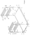
- the container can be used for transporting ceramic product exhibitor panels or others and is complemented with reeds that separate and immobilize the merchandise, formed by equal, parallel, coplanar and equidistant tube or rod pieces attached by an end to a stiff horizontal support that has vertical prolongations on its ends. These are inserted into the squared tube butts of the fronts that the corner pillars carry near their ends so that said reeds are directed towards the inside of the container with the opposite rods prolonged two-by-two and the superimposed rods parallel on the same side, with each pair defining a vertical plane.
- the dismountable container is of the type that adopts a general straight-rectangular cell configuration.
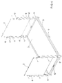
- Its bottom (3) is made up of a steel squared tube rectangular frame (5) with three longitudinal and two transversal reinforcements with suitable separation to insert the fork of the forklift trucks, forming a support grid of the bottom panel.
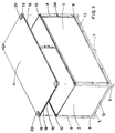
- the frame (5) has plugs (6) of the same tubular section on its four comers arranged orthogonally to the bottom plane, projecting out of it in short lower sections in order to constitute the container support legs. It also has two higher sections (7) in the center of its longest sides in order to assemble the corner pillars (8) (see Figures 1, 2 and 3).
- the corner pillars (8) are also made up of steel square tube with the same edge as the legs (6) and are assembled with them through a short T-section (9) where they fit in under pressure through their lower end. There is another T-section (10) projecting out of their upper end to assemble the lid (4).
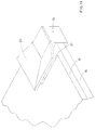
- These lugs (11) have butts (11') for said panels, formed by short sections of squared tube with a smaller edge than that of the pillars (8) (see Figures 1, 2 and 4).
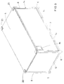
- the panels of the fronts (2) are placed with their inside face resting on the squared tube butts (11') and on the lugs (11) of the L-section of the corner pillars (8) to which they are attached by screws, whilst their inferior sides rest and are attached to C-section parts (12) arranged on the center of the smaller sides of the frame (5) of the bottom, with their open faces upward to receive the panels of the fronts (2) (see Figures 3 and 4).
- the sides (1) of the container are mounted framed in metallic sections (13) of sizes that fit tightly between the larger sides of the frame (5) of the bottom (3) on which they rest and the inside faces of the corner pillars (8) and are attached to the structural elements by means of screws through pairs of short flat parts (14) arranged symmetrically on the outside faces of the side frame (13), so that when the butts work they help to form straight dihedrons between the fronts (2) and sides (1) and between the sides and the bottom (3).
- Each side (1) is provided with a small superimposed and practicable frame (15) to house the transport identification data (see Figures 5, 9 and 10).
- the lid (4) or cover of the container is formed by a panel (16) the same size as the bottom (3), with rectangular notches (17) on its four comers intended to outline respective metallic parts located on the comers of a metallic support frame (18), consisting of a lower squared tube section (18) that fits into a T-section (10) under pressure projecting out of the upper end of each corner pillar and an upper section shaped like an inverted half frustum (20). It is intended to serve as a guide for its seating on the legs (8) of the container on top of the pile and to avoid relative, longitudinal or transversal sliding between the two upper and lower containers.
- the lid of the structural set is attached by screws passing through flat lugs (14) projecting out of the frame (3) of the corresponding sides (1) (see Figures 6, 7, 8 and 11).
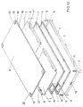
- the container can then be dismounted carrying out the procedure opposite to that of its assembly, forming a single compact package with its structural components arranged in the following order from top to bottom: the bottom (3) supported on its legs, on top of these the two sides (1), one on top of the other, the two fronts (2) arranged in coplanes and each one coupled to two corner pillars (8) and, finally, closing the set, the lid or cover (4) of the container with its comer parts tightly coupled to the T-sections projecting out of the upper ends of the legs (6) of the bottom (3) (see Figures 12 and 13).
- reeds (21) that separate and immobilize the merchandise, formed by equal, parallel, coplanar and equidistant tube or rod pieces (22) attached by an end to a stiff horizontal support (23) that has vertical prolongations (24) on its ends.
- reeds (21) that separate and immobilize the merchandise, formed by equal, parallel, coplanar and equidistant tube or rod pieces (22) attached by an end to a stiff horizontal support (23) that has vertical prolongations (24) on its ends.
Landscapes
- Engineering & Computer Science (AREA)
- Mechanical Engineering (AREA)
- Stackable Containers (AREA)
- Rigid Containers With Two Or More Constituent Elements (AREA)
- Cartons (AREA)
- Packaging Of Annular Or Rod-Shaped Articles, Wearing Apparel, Cassettes, Or The Like (AREA)
Abstract
Description
- It is modular in the sense that its sizes are submultiples of the standardized sizes for containers of 40 cubic feet, with the result that a certain number of the new modular containers fit exactly inside the former.
- It is dismountable and may be split up into the six elements that form its structure (two lateral panels, two front ends, bottom and lid or cover) which, in turn, can be superimposed forming a compact package, thus making it easy to return the dismounted container to its origin at a much lesser cost than mounted container, which pays an extra price for its volume although it transports nothing.
- It is able to be coupled, with two (or more) containers able to be juxtaposed along its sides or fronts to form a double capacity transport unit, thus eliminating the panels corresponding to the backed faces.
- It is stackable, as it permits two or more containers to be superimposed in height without the lower ones giving way and without loss of the whole set, as it has locking means on the ends of its structural elements that prevent relative, longitudinal or transversal sliding of the stacked containers.
- It is, therefore, versatile in its use (loaded or empty), in its capacity )simple or composed), in its parking (with one, two or more heights) and in its volume (mounted or dismounted).
Claims (9)
- Dismountable modular container of the type that has a general straight-rectangular cell shape, characterized by the fact that all its sizes are submultiples in the same proportion as the standardized sizes of containers of 40 cubic feet, so that a certain number of them fit exactly inside the latter. It can be split up into its six basic structural elements (two side panels (1), two fronts (2), bottom (3) and lid (4)), which can be superimposed forming a compact package to be returned to origin and reused; and because it is able to be coupled by lateral or front juxtaposition with one or more equal containers, forming greater capacity transportation units.
- Dismountable modular container, according to claim 1, characterized by the fact that its bottom (3) consists of a steel squared tube rectangular frame (5), with three longitudinal and two transversal reinforcements with suitable separation to insert the fork of the forklift trucks, forming a support grid of the bottom panel. The frame (5) has plugs (6) of the same tubular section on its four corners arranged orthogonally to the bottom plane, projecting out of it in short lower sections in order to constitute the container support legs. It also has two higher sections (7) in the center of its longest sides in order to assemble the corner pillars (8) (see Figures 1, 2 and 3).
- Dismountable modular container, according to claim 1, characterized by the fact that the comer pillars (8) are also made of steel squared tube with the same edge as the legs (6) and are assembled with them through a short T-section (9) where they fit in under pressure through their lower end. There is another T-section (10) projecting out of their upper end to assemble the lid (4). On their opposite inside faces there are four pairs of L-section lugs (11) arranged in inverse symmetry, with respective screwed holes (12) on their free wings to attach the panels of the fronts (2). These lugs (11) have butts (11') for said panels, formed by short sections of squared tube with a smaller edge than that of the pillars (8) (see Figures 1, 2 and 4).
- Dismountable modular container, according to claim 1, characterized by the fact that the panels of the fronts (2) are placed with their inside face resting on the squared tube butts (11') and on the lugs (11) of the L-section of the corner pillars (8) to which they are attached by screws, whilst their inferior sides rest and are attached to C-section parts (12) arranged on the center of the smaller sides of the frame (5) of the bottom, with their open faces upward to receive the panels of the fronts (2) (see Figures 3 and 4).
- Dismountable modular container, according to claim 1, characterized by the fact that the sides (1) of the container are mounted framed in metallic sections (13) of sizes that fit tightly between the larger sides of the frame (5) of the bottom (3) on which they rest and the inside faces of the corner pillars (8) and are attached to the structural elements by means of screws through pairs of short flat parts (14) arranged symmetrically on the outside faces of the side frame (13), so that when the butts work they help to form straight dihedrons between the fronts (2) and sides (1) and between the sides and the bottom (3). Each side (1) is provided with a small superimposed and practicable frame (15) to house the transport identification data (see Figures 5, 9 and 10).
- Dismountable modular container, according to claim 1, characterized by the fact that the lid (4) or cover of the container is formed by a panel (16) the same size as the bottom (3), with rectangular notches (17) on its four comers intended to outline respective metallic parts located on the comers of a metallic support frame (18), consisting of a lower squared tube section (18) that fits into a T-section (10) under pressure projecting out of the upper end of each corner pillar and an upper section shaped like an inverted half frustum (20). It is intended to serve as a guide for its seating on the legs (8) of the container on top of the pile and to avoid relative, longitudinal or transversal sliding between the two upper and lower containers. The lid of the structural set is attached by screws passing through flat lugs (14) projecting out of the frame (3) of the corresponding sides (1) (see Figures 6, 7, 8 and 11).
- Dismountable modular container, according to claim 1, characterized by the fact that once the container is unloaded at its destination it can then be dismounted carrying out the procedure opposite to that of its assembly, forming a single compact package with its structural components arranged in the following order from top to bottom: the bottom (3) supported on its legs, on top of these the two sides (1), one on top of the other, the two fronts (2) arranged in coplanes and each one coupled to two corner pillars (8) and, finally, closing the set, the lid or cover (4) of the container with its comer parts tightly coupled to the T-sections projecting out of the upper ends of the legs (6) of the bottom (3) (see Figures 12 and 13).
- Dismountable modular container, according to claim 1, characterized by the fact that the juxtaposition of the containers, usually by their fronts, permits the formation of a double capacity transportation unit, eliminating the panels corresponding to the backed faces and firmly joining the corner pillars (8) that delimit said faces (see Figures 14 and 15).
- Dismountable modular container, according to claim 1, characterized by the fact that in a special application, it can be used for transporting ceramic product exhibitor panels or others and is complemented with reeds (21) that separate and immobilize the merchandise, formed by equal, parallel, coplanar and equidistant tube or rod pieces (22) attached by an end to a stiff horizontal support (23) that has vertical prolongations (24) on its ends. These are inserted into the squared tube butts (11) of the fronts that the comer pillars (8) carry near their ends so that said reeds (21) are directed towards the inside of the container with the opposite rods (22) prolonged two-by-two and the superimposed rods parallel on the same side, with each pair defining a vertical plane (see Figures 16 and 17).
Applications Claiming Priority (2)
| Application Number | Priority Date | Filing Date | Title |
|---|---|---|---|
| ES200002085 | 2000-08-16 | ||
| ES200002085A ES2193808B1 (en) | 2000-08-16 | 2000-08-16 | REMOVABLE MODULAR CONTAINER. |
Publications (2)
| Publication Number | Publication Date |
|---|---|
| EP1182149A2 true EP1182149A2 (en) | 2002-02-27 |
| EP1182149A3 EP1182149A3 (en) | 2003-10-01 |
Family
ID=8494721
Family Applications (1)
| Application Number | Title | Priority Date | Filing Date |
|---|---|---|---|
| EP01500063A Withdrawn EP1182149A3 (en) | 2000-08-16 | 2001-03-13 | Dismountable modular container |
Country Status (2)
| Country | Link |
|---|---|
| EP (1) | EP1182149A3 (en) |
| ES (1) | ES2193808B1 (en) |
Cited By (11)
| Publication number | Priority date | Publication date | Assignee | Title |
|---|---|---|---|---|
| GB2410938A (en) * | 2004-02-12 | 2005-08-17 | Materials Handling Solutions U | Structure for containing and transporting materials |
| WO2006021719A1 (en) | 2004-07-30 | 2006-03-02 | Etablissements Serge Beaudonnet | CONTAINER OR EQUIPMENT OF THE SAME MODULABLE TYPE READY TO INSTALL |
| AU2002300332B2 (en) * | 2001-07-31 | 2006-07-06 | Kernohan Engineering Limited | Storage System and Apparatus |
| USD557910S1 (en) | 2006-10-23 | 2007-12-25 | J.F. Meskill Enterprises, Llc | Step stool |
| GB2443758A (en) * | 2004-02-12 | 2008-05-14 | Materials Handling Solutions U | Structure for holding and transporting materials |
| WO2009149659A1 (en) * | 2008-06-13 | 2009-12-17 | 华为技术有限公司 | Method for packaging electronic device and packaging turnover rack |
| CN101602425B (en) * | 2008-06-13 | 2011-05-04 | 华为技术有限公司 | Packaging turnover frame, packaging turnover frame assembly and electric equipment assembly |
| CN102092522B (en) * | 2009-12-14 | 2013-05-01 | 中国国际海运集装箱(集团)股份有限公司 | Transportation frame |
| EP2719640A1 (en) * | 2012-10-15 | 2014-04-16 | Ferran López Navarro | Dismountable and reusable shipping container and method for automatically dismounting such shipping container |
| IT202100019025A1 (en) | 2021-07-19 | 2023-01-19 | Enrico Solazzi | MODULAR CONTAINER FOR THE STORAGE AND TRANSPORT OF OBJECTS |
| CN118458160A (en) * | 2024-05-31 | 2024-08-09 | 南通中集特种运输设备制造有限公司 | Frame box |
Families Citing this family (2)
| Publication number | Priority date | Publication date | Assignee | Title |
|---|---|---|---|---|
| ES2253122B1 (en) * | 2004-11-11 | 2007-08-01 | Gamesa Eolica, S.A. Sociedad Unipersonal | CONTAINER FOR THE TRANSPORTATION OF BLADES. |
| ES2531428B2 (en) * | 2014-10-08 | 2015-11-03 | Jesús GARCÍA LÓPEZ | Container joining system |
Family Cites Families (5)
| Publication number | Priority date | Publication date | Assignee | Title |
|---|---|---|---|---|
| GB1024728A (en) * | 1963-10-07 | 1966-04-06 | Gordon Henry Johnson | Material handling containers |
| US3401814A (en) * | 1967-03-07 | 1968-09-17 | Collapsible Container Corp | Collapsible shipping container |
| GB2177375A (en) * | 1985-04-11 | 1987-01-21 | Michael Thomas Beckett | Modular containers |
| DE8526838U1 (en) * | 1985-09-19 | 1987-01-22 | Brüggemann & Brand GmbH & Co KG, 5802 Wetter | Demountable container |
| FR2732313B1 (en) * | 1995-03-28 | 1997-05-16 | Giat Ind Sa | TRANSPORT CONTAINER SUITABLE FOR MODULAR ASSEMBLY |
-
2000
- 2000-08-16 ES ES200002085A patent/ES2193808B1/en not_active Expired - Fee Related
-
2001
- 2001-03-13 EP EP01500063A patent/EP1182149A3/en not_active Withdrawn
Cited By (13)
| Publication number | Priority date | Publication date | Assignee | Title |
|---|---|---|---|---|
| AU2002300332B2 (en) * | 2001-07-31 | 2006-07-06 | Kernohan Engineering Limited | Storage System and Apparatus |
| GB2410938A (en) * | 2004-02-12 | 2005-08-17 | Materials Handling Solutions U | Structure for containing and transporting materials |
| GB2443758A (en) * | 2004-02-12 | 2008-05-14 | Materials Handling Solutions U | Structure for holding and transporting materials |
| WO2006021719A1 (en) | 2004-07-30 | 2006-03-02 | Etablissements Serge Beaudonnet | CONTAINER OR EQUIPMENT OF THE SAME MODULABLE TYPE READY TO INSTALL |
| US8251237B2 (en) | 2004-07-30 | 2012-08-28 | Etablissements Serge Beaudonnet | Ready-to-mount, modular container or same-type equipment |
| USD557910S1 (en) | 2006-10-23 | 2007-12-25 | J.F. Meskill Enterprises, Llc | Step stool |
| CN101602425B (en) * | 2008-06-13 | 2011-05-04 | 华为技术有限公司 | Packaging turnover frame, packaging turnover frame assembly and electric equipment assembly |
| WO2009149659A1 (en) * | 2008-06-13 | 2009-12-17 | 华为技术有限公司 | Method for packaging electronic device and packaging turnover rack |
| CN102092522B (en) * | 2009-12-14 | 2013-05-01 | 中国国际海运集装箱(集团)股份有限公司 | Transportation frame |
| EP2719640A1 (en) * | 2012-10-15 | 2014-04-16 | Ferran López Navarro | Dismountable and reusable shipping container and method for automatically dismounting such shipping container |
| WO2014060816A1 (en) * | 2012-10-15 | 2014-04-24 | Alejandro Agusti Larumbe | Reusable dismountable container and method for automatically dismounting said container |
| IT202100019025A1 (en) | 2021-07-19 | 2023-01-19 | Enrico Solazzi | MODULAR CONTAINER FOR THE STORAGE AND TRANSPORT OF OBJECTS |
| CN118458160A (en) * | 2024-05-31 | 2024-08-09 | 南通中集特种运输设备制造有限公司 | Frame box |
Also Published As
| Publication number | Publication date |
|---|---|
| ES2193808A1 (en) | 2003-11-01 |
| EP1182149A3 (en) | 2003-10-01 |
| ES2193808B1 (en) | 2004-11-01 |
Similar Documents
| Publication | Publication Date | Title |
|---|---|---|
| US5765707A (en) | Modular shipping container | |
| US5413236A (en) | Modular shipping container | |
| US3348723A (en) | Receptacle | |
| US2775360A (en) | Material handling container | |
| US4643314A (en) | Container construction | |
| US9340322B2 (en) | Transport pallet | |
| US3797691A (en) | Modular cargo container for transport vehicles | |
| JP5553453B2 (en) | Transportation of goods | |
| US8905254B2 (en) | Transport of goods | |
| US6019226A (en) | Demountable palletized container | |
| US2683010A (en) | Pallet and spacer | |
| US3727785A (en) | Mobile cargo storage unit | |
| CN105026274B (en) | Detachable Self-Assembly Structure | |
| US4171058A (en) | Knock-down slot-lock container | |
| US9676515B2 (en) | Panel and support structure for collapsible container, and collapsible container | |
| US2964211A (en) | Nesting basket construction | |
| CA2281714C (en) | Loading unit for air freight | |
| EP1182149A3 (en) | Dismountable modular container | |
| US3253707A (en) | Package | |
| US3116847A (en) | Knockdown container | |
| US2897995A (en) | Collapsible container and pallet assembly | |
| KR20240063864A (en) | Reinforcement systems and methods for supporting stacked boxes and containers | |
| US20110047890A1 (en) | Method of Packaging a Storage Building Kit of Parts | |
| US20030051641A1 (en) | Base section for a collapsible container | |
| EP0703158A1 (en) | Packing system |
Legal Events
| Date | Code | Title | Description |
|---|---|---|---|
| PUAI | Public reference made under article 153(3) epc to a published international application that has entered the european phase |
Free format text: ORIGINAL CODE: 0009012 |
|
| AK | Designated contracting states |
Kind code of ref document: A2 Designated state(s): AT BE CH CY DE DK ES FI FR GB GR IE IT LI LU MC NL PT SE TR |
|
| AX | Request for extension of the european patent |
Free format text: AL;LT;LV;MK;RO;SI |
|
| PUAL | Search report despatched |
Free format text: ORIGINAL CODE: 0009013 |
|
| AK | Designated contracting states |
Kind code of ref document: A3 Designated state(s): AT BE CH CY DE DK ES FI FR GB GR IE IT LI LU MC NL PT SE TR |
|
| AX | Request for extension of the european patent |
Extension state: AL LT LV MK RO SI |
|
| AKX | Designation fees paid |
Designated state(s): AT BE CH CY DE DK ES FI FR GB GR IE IT LI LU MC NL PT SE TR |
|
| STAA | Information on the status of an ep patent application or granted ep patent |
Free format text: STATUS: THE APPLICATION IS DEEMED TO BE WITHDRAWN |
|
| 18D | Application deemed to be withdrawn |
Effective date: 20040402 |