EP1182526A2 - Contrôle continu dans un outillage d'usinage de semiconduteurs basé sur une fonction d'image spéculaire - Google Patents
Contrôle continu dans un outillage d'usinage de semiconduteurs basé sur une fonction d'image spéculaire Download PDFInfo
- Publication number
- EP1182526A2 EP1182526A2 EP01119359A EP01119359A EP1182526A2 EP 1182526 A2 EP1182526 A2 EP 1182526A2 EP 01119359 A EP01119359 A EP 01119359A EP 01119359 A EP01119359 A EP 01119359A EP 1182526 A2 EP1182526 A2 EP 1182526A2
- Authority
- EP
- European Patent Office
- Prior art keywords
- run
- tool
- mirror image
- goal
- recipe
- Prior art date
- Legal status (The legal status is an assumption and is not a legal conclusion. Google has not performed a legal analysis and makes no representation as to the accuracy of the status listed.)
- Withdrawn
Links
Images


Classifications
-
- G—PHYSICS
- G05—CONTROLLING; REGULATING
- G05B—CONTROL OR REGULATING SYSTEMS IN GENERAL; FUNCTIONAL ELEMENTS OF SUCH SYSTEMS; MONITORING OR TESTING ARRANGEMENTS FOR SUCH SYSTEMS OR ELEMENTS
- G05B19/00—Program-control systems
- G05B19/02—Program-control systems electric
- G05B19/418—Total factory control, i.e. centrally controlling a plurality of machines, e.g. direct or distributed numerical control [DNC], flexible manufacturing systems [FMS], integrated manufacturing systems [IMS] or computer integrated manufacturing [CIM]
- G05B19/41865—Total factory control, i.e. centrally controlling a plurality of machines, e.g. direct or distributed numerical control [DNC], flexible manufacturing systems [FMS], integrated manufacturing systems [IMS] or computer integrated manufacturing [CIM] characterised by job scheduling, process planning, material flow
-
- H—ELECTRICITY
- H10—SEMICONDUCTOR DEVICES; ELECTRIC SOLID-STATE DEVICES NOT OTHERWISE PROVIDED FOR
- H10P—GENERIC PROCESSES OR APPARATUS FOR THE MANUFACTURE OR TREATMENT OF DEVICES COVERED BY CLASS H10
- H10P95/00—Generic processes or apparatus for manufacture or treatments not covered by the other groups of this subclass
-
- G—PHYSICS
- G05—CONTROLLING; REGULATING
- G05B—CONTROL OR REGULATING SYSTEMS IN GENERAL; FUNCTIONAL ELEMENTS OF SUCH SYSTEMS; MONITORING OR TESTING ARRANGEMENTS FOR SUCH SYSTEMS OR ELEMENTS
- G05B2219/00—Program-control systems
- G05B2219/30—Nc systems
- G05B2219/31—From computer integrated manufacturing till monitoring
- G05B2219/31432—Keep track of conveyed workpiece, batch, tool, conditions of stations, cells
-
- G—PHYSICS
- G05—CONTROLLING; REGULATING
- G05B—CONTROL OR REGULATING SYSTEMS IN GENERAL; FUNCTIONAL ELEMENTS OF SUCH SYSTEMS; MONITORING OR TESTING ARRANGEMENTS FOR SUCH SYSTEMS OR ELEMENTS
- G05B2219/00—Program-control systems
- G05B2219/30—Nc systems
- G05B2219/31—From computer integrated manufacturing till monitoring
- G05B2219/31443—Keep track of nc program, recipe program
-
- G—PHYSICS
- G05—CONTROLLING; REGULATING
- G05B—CONTROL OR REGULATING SYSTEMS IN GENERAL; FUNCTIONAL ELEMENTS OF SUCH SYSTEMS; MONITORING OR TESTING ARRANGEMENTS FOR SUCH SYSTEMS OR ELEMENTS
- G05B2219/00—Program-control systems
- G05B2219/30—Nc systems
- G05B2219/45—Nc applications
- G05B2219/45026—Circuit board, pcb
-
- G—PHYSICS
- G05—CONTROLLING; REGULATING
- G05B—CONTROL OR REGULATING SYSTEMS IN GENERAL; FUNCTIONAL ELEMENTS OF SUCH SYSTEMS; MONITORING OR TESTING ARRANGEMENTS FOR SUCH SYSTEMS OR ELEMENTS
- G05B2219/00—Program-control systems
- G05B2219/30—Nc systems
- G05B2219/45—Nc applications
- G05B2219/45232—CMP chemical mechanical polishing of wafer
-
- Y—GENERAL TAGGING OF NEW TECHNOLOGICAL DEVELOPMENTS; GENERAL TAGGING OF CROSS-SECTIONAL TECHNOLOGIES SPANNING OVER SEVERAL SECTIONS OF THE IPC; TECHNICAL SUBJECTS COVERED BY FORMER USPC CROSS-REFERENCE ART COLLECTIONS [XRACs] AND DIGESTS
- Y02—TECHNOLOGIES OR APPLICATIONS FOR MITIGATION OR ADAPTATION AGAINST CLIMATE CHANGE
- Y02P—CLIMATE CHANGE MITIGATION TECHNOLOGIES IN THE PRODUCTION OR PROCESSING OF GOODS
- Y02P90/00—Enabling technologies with a potential contribution to greenhouse gas [GHG] emissions mitigation
- Y02P90/02—Total factory control, e.g. smart factories, flexible manufacturing systems [FMS] or integrated manufacturing systems [IMS]
Definitions
- Figure 1 shows a schematic diagram of the functioning of a generic semiconductor fabrication system 100.
- fabrication system 100 comprises inputs in the form of operational parameters 102a, 102b, and 102c supplied to fabrication tool 104.
- Operational parameters 102a-c are settings governing function of fabrication tool 104 for a particular run.
- tool 104 Based upon the input of operational parameters, tool 104 performs a fabrication process upon a semiconductor substrate.
- the character of this fabrication process is represented by process results 106a and 106b.
- Process results 106a and 106b may be data measured directly from the changed semiconductor substrate, or may be derived from data measured from the changed semiconductor substrate.
- fabrication tool 104 functions on every run to produce the same process result from given operational parameter settings.
- operation of the fabrication tool is subject to a host of complex variables, not all of which can be reliably controlled by the user. Therefore, the performance of the fabrication tool will vary somewhat over time, and the relationship between given operational parameters and process results will drift from run-to-run.
- the present invention relates to a method for minimizing run-to-run variation in operation of a semiconductor fabrication tool.
- run-to-run variation in process results are minimized by comparing an output from a most recent processing run to a desired fixed goal. A difference between the fixed goal and the output is then calculated. Addition of the difference to the fixed goal creates a mirror image of the output around the fixed goal. The mirror image is used as a target to predict tool behavior for a subsequent processing run in order to bring process results closer to the desired goal.
- the method in accordance with the present invention is particularly suited for minimizing variation of a semiconductor fabrication process whose behavior is predicted utilizing a data-based modeling engine.
- the present invention is not limited to controlling this type of fabrication process.
- One embodiment of the method in accordance with the present invention comprises the steps of determining a goal of a process result sought to be produced by the tool, and detecting an actual output of the process result from a most recent run of the tool according to an initial recipe.
- a difference is calculated by subtracting the goal from the actual output, and a mirror image target is calculated by adding the difference to the goal.
- a suggested recipe is generated from the mirror image target; and a subsequent run of the tool is performed utilizing the suggested recipe to produce a second actual output of the process result that is similar to the goal.
- a goal represents a process result desired from operation of the tool.
- the mirror image target is generated by adding the goal to a difference between an output from a previous tool run and the goal. Prediction of tool performance is based upon a data-based modeling engine utilizing a reference library correlating operational parameters with observed process results for prior tool runs.
- the mirror image target vector is compared to the reference library and serves as a basis for generating the recipe for the subsequent process run. This recipe automatically brings operation of the tool back toward the goal.
- the method may further include comparison of the suggested recipe with the recipe of the prior run to determine whether run-to-run variation is serious enough to warrant a change in tool conditions, or whether run-to-run variation is so serious as to indicate a major tool problem.
- Generation of the mirror image target, and utilization of the mirror image target to create a new process recipe eliminates effort and uncertainty associated with conventional nonsystematic analysis of tool variation, followed by manual intervention by the operator to adjust tool parameters to reduce such variation.
- Fig. 1 is a schematic representing operation of a generic semiconductor fabrication tool.
- Fig. 2 shows a CMP tool suitable for run-to-run control in accordance with one embodiment of the present invention.
- Fig. 3 is a schematic representing operation of a CMP fabrication tool.
- Fig. 4 is a schematic diagram representing a feed-forward data-based model for the CMP tool shown in Fig. 2.
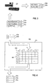
- Fig. 5 is plots a second process result versus a first process result and illustrates the general approach of a run-to-run control method in accordance with one embodiment of the present invention.
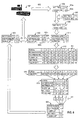
- Fig. 6 is a flow chart illustrating the detailed steps of one embodiment of a method for run-to-run control over a CMP tool in accordance with the present invention.
- Fig. 7 plots material thickness versus polish uniformity and illustrate generation of the mirror image vector from the target vector and the most recent output vector.
- the method of the present invention can be employed to minimize run-to-run variation of a variety of semiconductor processes, including but not limited to deposition processes, etch processes, and implantation processes.
- semiconductor processes including but not limited to deposition processes, etch processes, and implantation processes.
- CMP chemical mechanical polishing
- FIG. 2 shows a simple schematic diagram of a chemical mechanical polishing (CMP) tool 200.
- Tool 200 can be a Mirra® CMP tool manufactured by Applied Materials, Inc. of Santa Clara, California. A description of a similar polisher may be found in United States Patent No. 5,738,574, the entire disclosure of which is incorporated herein by reference.
- CMP tool 200 includes a series of polishing stations 202 and a transfer station 204. Transfer station 204 serves multiple functions, including receiving individual substrates 206 from robot 208, washing substrates 206, and loading substrates 206 onto carrier heads 210.
- each polishing station 202 includes a rotatable platen 212 that supports a polishing pad 214, e.g.
- Rotatable carousel 216 holds four carrier heads 218 supported above the polishing stations 202. Carousel 216 rotates to carry substrates 206 between polishing stations 202 and transfer station 204.
- an unpolished substrate is retrieved by robot 208 and placed into transfer station 204.
- carrier head 218 engages substrate 206 by vacuum suction, and then places substrate 206 into contact with rotating platen 212 and polishing pad 214.
- Slurry 220 is dispensed from slurry reservoir 222 onto the surface of pad 214 and pad 214 is biased against the surface of substrate 206 and rotated. The contact of pad 214 against the surface of substrate 206 results in the removal of semiconductor material from substrate 206 by a combination of chemical and mechanical action.
- Processor 224 controls operation of CMP tool 200 by executing computer instructions stored in a memory 226.
- Processor 224 is in electrical communication with, and exerts control over, operation of platen 212 and slurry reservoir 222. In this manner, processor 224 determines operational parameters of the speed of rotation of platen 212 and the pressure applied by pad 214, and also the pH of dispensed slurry 220 from reservoir 222.
- Tool 200 further includes sensors 228. Sensors 228 receive data from substrate 206. Sensors 228 can be part of an in-situ monitoring system at the polishing station, or can be part of an in-line or off-line metrology station. Data from sensors 228 is communicated to processor 224, which then determines process results of substrate thickness and polish uniformity based upon the operation of tool 200. Processor 224 also contains circuitry for performing the method of run-to-run control whose steps are detailed below.
- FIG. 3 shows a schematic diagram representing the functioning of the CMP tool of Fig. 2.
- CMP tool 200 receives inputs in the form of operational parameters 230a-c.
- categories of operational parameters 230a-c input to CMP tool 200 include platen rotation rate, pad pressure, and slurry pH.
- these categories of operational parameters are merely examples and other categories of CMP operational parameters could be utilized by the present invention.
- CMP tool 200 Based upon operational parameters 230a-c, CMP tool 200 functions to planarize a semiconductor substrate. The character of this planarization is represented by process results 232a-b. As shown in Figure 3, process results 232a-b for CMP tool 200 include thickness of semiconductor material remaining after polishing, and uniformity of semiconductor material removed from the substrate. Again, these categories of process results are merely examples and other categories of results from CMP processing could be utilized by the present invention.
- CMP tool 200 will function on every run to produce the same process result values from given operational parameters.
- CMP tool 200 is extremely complex and its operation is subject to a host of variables, only some of which can be reliably controlled by the user. Therefore, performance of CMP tool 200 will vary or drift over time. Given the drift in the relationship between input operational parameters and output process results from run-to-run, the operator must be able to predict process results given modified tool operational parameters. This prediction is accomplished through the use of modeling.
- Model 400 operates solely upon the basis of data collected from prior tool runs. Specifically, desired process results 432a-b are supplied as an input to modeling engine 404. Modeling engine 404 includes library 406 of process results obtained from prior tool runs 407 under a variety of operational parameters. Based upon process results 432a-b input to engine 404, engine 404 references library 406 and outputs modeled operational parameters 430a-c most likely to produce process results 432a-b.
- the prediction of data-based modeling engine 404 is determined solely by actual data compiled in reference library 406. Specifically, modeling engine 404 is limited to comparing the process result supplied to data in the form of specific prior fabrication runs. Data-based modeling engine 404 does not attempt to generalize the relationship between prior process results and corresponding operational parameters utilizing a mathematical formula or equation. Because data-based modeling engine 404 considers as inputs only process results reflecting a fixed desired goal, engine 404 will repeatedly output the same process parameters regardless of actual tool performance. Data-based modeling engine 404 thus cannot account for drift in the input-output relationship of a complex fabrication tool.
- Figure 5 shows the general approach to run-to-run control in accordance with one embodiment of the present invention.
- Actual output 500 comprising first and second process results of a fabrication tool are compared with a desired fixed goal 502 to create a mirror image target 506 about goal 502.
- this mirror image target is then fed to a data-based modeling engine to produce operational parameters calculated to bring operation of the fabrication tool back toward the desired fixed goal 502.
- FIG. 6 shows the detailed steps of method 600 for run-to-run control over CMP tool 601 to compensate for variation and bring the process results closer to a desired goal.
- CMP tool 601 receives an initial recipe 602 comprising operational parameters 602a-c of pad rotation rate, pad pressure, and slurry pH.
- CMP tool 601 is then operated according to initial recipe 602 to perform a CMP process on a substrate, such that output vector 604 comprising process results 604a-b of material thickness and polish uniformity is produced.
- operation of CMP tool 601 at an initial recipe 602 of pad rotation rate of 5.2, pad pressure of 6.0 and slurry pH of 1.3 produces output vector 604 of material thickness of 10.0 and polish uniformity of 2.4.
- the valves given for the operational parameters 602a-c and corresponding process results 604a-b are for illustration purposes only, and do not necessarily reflect operational parameters or sensed etch results of an actual plasma etching tool.
- Fig. 6 shows the next step of run-to-run control method 600, wherein output vector 604 is compared with goal vector 606 to generate mirror image target vector 608.
- Goal vector 606 comprises the same two components (material thickness and polish uniformity) comprising output vector 604. Values of the process results for goal vector 606 are those sought to be achieved by operation of the tool.
- Fig. 7 plots material thickness versus polish uniformity and depicts calculation of mirror image target vector 608 from goal vector 606 and output vector 602.
- the first step in generating mirror image target vector 608 is to plot the process results of goal vector 606 and output vector 602.
- Difference vector 610 corresponds to the difference between output vector 602 and goal vector 606.
- Mirror image target vector 608 is then generated from the sum of difference vector 610 and goal vector 606.
- Mirror image target vector 608 represents conditions anticipated to bring operation of tool 601 back to the desired goal on a subsequent processing run.
- mirror image target vector 608 is combined with operational parameters 602a-c of initial recipe 602 to produce reference vector 611.
- Reference vector 611 is then compared to library data file 612.
- Library data file 612 is a compilation of individual vectors 614 reflecting prior process results corresponding to a variety of operational parameters.
- Comparison of reference vector 608 to library data file 612 generates similarity coefficient 616 for each vector 614 of library data file 612.
- the value of similarity coefficient 616 is calculated utilizing the K-nearest neighbor approach, as would be understood by a person of ordinary skill in the art. This ensures that the least amount of change is made to output vector 102 of the most recent run in order to correct for variation.
- calculation of similarity coefficient 616 is based not only on process results but also upon operational parameters. This serves as a check on the similarity determination, ensuring that vector 614 producing similar process results from radically different operational parameters is not considered similar.
- similarity coefficient 616 may discount or emphasize the effect of similarity between operational parameters versus similarity between sensed etch results, for reference vector 611 and individual vectors 614 of library 612.
- subset 618 of individual vectors 620 closely resembling reference vector 608 is compiled from library data file 612. Subset 618 reflects tool operating parameters most likely to produce an output vector corresponding to mirror image target vector 608.
- weights 622 are assigned to each individual vector 620 of subset 618.
- the method of assigning weights 622 can again vary depending upon characteristics of a particular etch process and/or operator preference.
- weights may be assigned to individual vectors based upon a formula that takes into account the similarity coefficient described above.
- Weighted vectors of subset 618 are then linearly added to produce combined vector 623.
- the operational parameter information of combined vector 623 represents suggested recipe 624 that is intended to bring CMP process back into conformity with goal vector 606.
- CMP tool 601 may utilize suggested recipe 624 in the subsequent run in order to correct for variation.
- suggested recipe 624 is extremely similar to initial recipe 602, a decision may be made not to disturb existing tool conditions and suggested recipe 624 may be not be adopted by tool 601. The subsequent processing run of tool 601 would simply implement initial recipe 602.
- suggested recipe 624 represents a radical departure from initial recipe 602
- a serious problem with tool 601 may be indicated.
- the tool may also disregard suggested recipe 624 and instead emit an alarm alerting the operator to the problem.
- Conditions governing an appropriate course of action in a specific case may be programmed according to preferences of the operator or to dictates of a particular application.
- etch tool 601 If a decision is ultimately made to provide suggested recipe 624 to etch tool 601, the next run of etch tool 601 will conform to the operational parameters provided by suggested recipe 624. These operational parameters would be expected to bring operation of tool 601 back toward goal vector 606. In this manner, run-to-run control over the etching process is accomplished.
- the method of run-to-run control in accordance with one embodiment of the present invention offers a number of advantages over prior techniques.
- One advantage is reduction in effort required by the operator. Specifically, based upon observed outputs of the tool, the mirror image target is automatically calculated by the processor controlling the tool. Apart from possibly approving or disregarding the recipe suggested by the method, no manual intervention by the operator is required to accomplish run-to-run control, and the operator can focus on other tasks.
- Another important advantage of the method in accordance with one embodiment of the present invention is reduction in non-uniformity of run-to-run control.
- the tool operator was required to manually determine operating parameters at which the corresponding process results would move the tool back in line with a desired goal.
- the act of generating such operating conditions was frequently performed by trial and error in a non-systematic way. Because the conventional technique lacked a consistent methodology, correction of process variation was inconsistent from run-to-run, tool-to-tool, and user-to-user.
- run-to-run control is automated and performed according to objective variables such as measured process results and a predetermined goal. This approach leads to consistent manipulation of the tool and to readily reproducible results.
- the method in accordance with one embodiment of the present invention also offers the advantage of increased responsiveness. Rather than requiring the operator to measure process results and perform adjustments based upon manual calculations, the present technique performs these tasks automatically at the conclusion of each fabrication run. The operator is provided with a suggested recipe almost instantaneously, and has plenty of time to consider other factors in deciding whether or not to implement the suggested recipe in the next tool run.
- mirror image target vector from the goal vector and output vector in two-dimensional space
- the mirror image vector could be generated from output and goal vectors reflecting three, four, or even N different process results, with the output, goal, difference, and mirror image target vectors correspondingly plotted in N-dimensional space.
- the method described above may cause oscillation of operational parameters and sensed results between suggested recipes over consecutive tool runs. Such oscillation would likely occur around a desired goal that is never precisely met, and may be attributable to features of the modeling engine rather than actual run-to-run variation.
- the method may include the use of a damping factor.
- a damping factor could be utilized in generating the mirror image target vector from the goal vector according to Equation (II) below:
- (II) mirror image vector target vector + A*(output vector - target vector), where A represents a damping factor of between 0 and 1 and reflects any prior repeated fluctuation of the results of prior process runs.
Landscapes
- Engineering & Computer Science (AREA)
- General Engineering & Computer Science (AREA)
- Manufacturing & Machinery (AREA)
- Quality & Reliability (AREA)
- Physics & Mathematics (AREA)
- General Physics & Mathematics (AREA)
- Automation & Control Theory (AREA)
- Drying Of Semiconductors (AREA)
- Weting (AREA)
- Mechanical Treatment Of Semiconductor (AREA)
- Feedback Control In General (AREA)
- Management, Administration, Business Operations System, And Electronic Commerce (AREA)
Applications Claiming Priority (2)
| Application Number | Priority Date | Filing Date | Title |
|---|---|---|---|
| US639140 | 2000-08-15 | ||
| US09/639,140 US6625513B1 (en) | 2000-08-15 | 2000-08-15 | Run-to-run control over semiconductor processing tool based upon mirror image target |
Publications (2)
| Publication Number | Publication Date |
|---|---|
| EP1182526A2 true EP1182526A2 (fr) | 2002-02-27 |
| EP1182526A3 EP1182526A3 (fr) | 2004-12-08 |
Family
ID=24562894
Family Applications (1)
| Application Number | Title | Priority Date | Filing Date |
|---|---|---|---|
| EP01119359A Withdrawn EP1182526A3 (fr) | 2000-08-15 | 2001-08-10 | Contrôle continu dans un outillage d'usinage de semiconduteurs basé sur une fonction d'image spéculaire |
Country Status (6)
| Country | Link |
|---|---|
| US (1) | US6625513B1 (fr) |
| EP (1) | EP1182526A3 (fr) |
| JP (1) | JP2002208544A (fr) |
| KR (1) | KR100768015B1 (fr) |
| SG (1) | SG117393A1 (fr) |
| TW (1) | TW516080B (fr) |
Cited By (26)
| Publication number | Priority date | Publication date | Assignee | Title |
|---|---|---|---|---|
| WO2002103777A1 (fr) * | 2001-06-19 | 2002-12-27 | Applied Materials, Inc. | Commande a reaction d'un dispositif de polissage chimique mecanique par manipulation de profils de taux d'elimination |
| US6640151B1 (en) | 1999-12-22 | 2003-10-28 | Applied Materials, Inc. | Multi-tool control system, method and medium |
| US6708074B1 (en) | 2000-08-11 | 2004-03-16 | Applied Materials, Inc. | Generic interface builder |
| US6910947B2 (en) | 2001-06-19 | 2005-06-28 | Applied Materials, Inc. | Control of chemical mechanical polishing pad conditioner directional velocity to improve pad life |
| US6913938B2 (en) | 2001-06-19 | 2005-07-05 | Applied Materials, Inc. | Feedback control of plasma-enhanced chemical vapor deposition processes |
| US6961626B1 (en) | 2004-05-28 | 2005-11-01 | Applied Materials, Inc | Dynamic offset and feedback threshold |
| US6984198B2 (en) | 2001-08-14 | 2006-01-10 | Applied Materials, Inc. | Experiment management system, method and medium |
| US6999836B2 (en) | 2002-08-01 | 2006-02-14 | Applied Materials, Inc. | Method, system, and medium for handling misrepresentative metrology data within an advanced process control system |
| US7047099B2 (en) | 2001-06-19 | 2006-05-16 | Applied Materials Inc. | Integrating tool, module, and fab level control |
| US7069101B1 (en) | 1999-07-29 | 2006-06-27 | Applied Materials, Inc. | Computer integrated manufacturing techniques |
| US7082345B2 (en) | 2001-06-19 | 2006-07-25 | Applied Materials, Inc. | Method, system and medium for process control for the matching of tools, chambers and/or other semiconductor-related entities |
| US7096085B2 (en) | 2004-05-28 | 2006-08-22 | Applied Materials | Process control by distinguishing a white noise component of a process variance |
| US7101799B2 (en) | 2001-06-19 | 2006-09-05 | Applied Materials, Inc. | Feedforward and feedback control for conditioning of chemical mechanical polishing pad |
| US7188142B2 (en) | 2000-11-30 | 2007-03-06 | Applied Materials, Inc. | Dynamic subject information generation in message services of distributed object systems in a semiconductor assembly line facility |
| US7205228B2 (en) | 2003-06-03 | 2007-04-17 | Applied Materials, Inc. | Selective metal encapsulation schemes |
| US7225047B2 (en) | 2002-03-19 | 2007-05-29 | Applied Materials, Inc. | Method, system and medium for controlling semiconductor wafer processes using critical dimension measurements |
| US7272459B2 (en) | 2002-11-15 | 2007-09-18 | Applied Materials, Inc. | Method, system and medium for controlling manufacture process having multivariate input parameters |
| US7333871B2 (en) | 2003-01-21 | 2008-02-19 | Applied Materials, Inc. | Automated design and execution of experiments with integrated model creation for semiconductor manufacturing tools |
| US7337019B2 (en) | 2001-07-16 | 2008-02-26 | Applied Materials, Inc. | Integration of fault detection with run-to-run control |
| US7356377B2 (en) | 2004-01-29 | 2008-04-08 | Applied Materials, Inc. | System, method, and medium for monitoring performance of an advanced process control system |
| US7354332B2 (en) | 2003-08-04 | 2008-04-08 | Applied Materials, Inc. | Technique for process-qualifying a semiconductor manufacturing tool using metrology data |
| EP1359470A3 (fr) * | 2002-04-30 | 2008-07-16 | Canon Kabushiki Kaisha | Système de gestion et appareil, leur méthode et méthode de fabrication d'un dispositif |
| WO2009016090A1 (fr) * | 2007-07-27 | 2009-02-05 | Fondazione Bruno Kessler | Procédé et dispositif correspondant utiles pour gérer des informations de recettes technologiques afin d'aider à définir des flux de traitement, notamment pour la mise au point et la production de dispositifs de microtechnologie et de nanotechnologie dans des laboratoires à salles blanches |
| US7698012B2 (en) | 2001-06-19 | 2010-04-13 | Applied Materials, Inc. | Dynamic metrology schemes and sampling schemes for advanced process control in semiconductor processing |
| US8005634B2 (en) | 2002-03-22 | 2011-08-23 | Applied Materials, Inc. | Copper wiring module control |
| WO2023039092A1 (fr) * | 2021-09-10 | 2023-03-16 | Applied Materials, Inc. | Utilisation d'informations de cartes élémentaires provenant d'une analyse par balayage linéaire de spectroscopie de rayons x à dispersion d'énergie pour créer des modèles de processus |
Families Citing this family (13)
| Publication number | Priority date | Publication date | Assignee | Title |
|---|---|---|---|---|
| JP3708031B2 (ja) * | 2001-06-29 | 2005-10-19 | 株式会社日立製作所 | プラズマ処理装置および処理方法 |
| US6616759B2 (en) * | 2001-09-06 | 2003-09-09 | Hitachi, Ltd. | Method of monitoring and/or controlling a semiconductor manufacturing apparatus and a system therefor |
| US6884147B2 (en) * | 2003-03-28 | 2005-04-26 | Yield Dynamics, Inc. | Method for chemical-mechanical polish control in semiconductor manufacturing |
| US8025759B2 (en) * | 2003-07-02 | 2011-09-27 | Ebara Corporation | Polishing apparatus and polishing method |
| TWI267012B (en) * | 2004-06-03 | 2006-11-21 | Univ Nat Cheng Kung | Quality prognostics system and method for manufacturing processes |
| CN101023429B (zh) * | 2004-07-02 | 2010-09-01 | 斯特拉斯鲍公司 | 用于处理晶片的方法和系统 |
| US20060240651A1 (en) * | 2005-04-26 | 2006-10-26 | Varian Semiconductor Equipment Associates, Inc. | Methods and apparatus for adjusting ion implant parameters for improved process control |
| US7248936B1 (en) | 2006-01-31 | 2007-07-24 | International Business Machines Corporation | Automated tool recipe verification and correction |
| US7305320B2 (en) | 2006-02-15 | 2007-12-04 | International Business Machines Corporation | Metrology tool recipe validator using best known methods |
| JP5224744B2 (ja) * | 2006-10-04 | 2013-07-03 | 株式会社日立国際電気 | 基板処理装置 |
| US7774082B2 (en) | 2006-10-05 | 2010-08-10 | Tokyo Electron Limited | Substrate processing method and storage medium having program stored therein |
| US20130017762A1 (en) * | 2011-07-15 | 2013-01-17 | Infineon Technologies Ag | Method and Apparatus for Determining a Measure of a Thickness of a Polishing Pad of a Polishing Machine |
| WO2019155928A1 (fr) * | 2018-02-08 | 2019-08-15 | 東京エレクトロン株式会社 | Dispositif de traitement d'informations, programme, dispositif d'exécution de processus de traitement et système de traitement d'informations |
Family Cites Families (15)
| Publication number | Priority date | Publication date | Assignee | Title |
|---|---|---|---|---|
| US5408405A (en) * | 1993-09-20 | 1995-04-18 | Texas Instruments Incorporated | Multi-variable statistical process controller for discrete manufacturing |
| US5526293A (en) * | 1993-12-17 | 1996-06-11 | Texas Instruments Inc. | System and method for controlling semiconductor wafer processing |
| US5646870A (en) * | 1995-02-13 | 1997-07-08 | Advanced Micro Devices, Inc. | Method for setting and adjusting process parameters to maintain acceptable critical dimensions across each die of mass-produced semiconductor wafers |
| US5917919A (en) * | 1995-12-04 | 1999-06-29 | Rosenthal; Felix | Method and apparatus for multi-channel active control of noise or vibration or of multi-channel separation of a signal from a noisy environment |
| KR0165320B1 (ko) * | 1995-12-27 | 1999-02-01 | 김광호 | 반도체 산화 공정의 소크타임 설정 방법 |
| US6445969B1 (en) * | 1997-01-27 | 2002-09-03 | Circuit Image Systems | Statistical process control integration systems and methods for monitoring manufacturing processes |
| US5926690A (en) * | 1997-05-28 | 1999-07-20 | Advanced Micro Devices, Inc. | Run-to-run control process for controlling critical dimensions |
| US6161054A (en) * | 1997-09-22 | 2000-12-12 | On-Line Technologies, Inc. | Cell control method and apparatus |
| JP4276711B2 (ja) * | 1998-01-05 | 2009-06-10 | 株式会社日立国際電気 | 半導体製造装置制御システム |
| US6230069B1 (en) * | 1998-06-26 | 2001-05-08 | Advanced Micro Devices, Inc. | System and method for controlling the manufacture of discrete parts in semiconductor fabrication using model predictive control |
| JP3349455B2 (ja) * | 1998-09-30 | 2002-11-25 | 宮崎沖電気株式会社 | 半導体製造装置のための管理方法および管理システム |
| EP1065567A3 (fr) * | 1999-06-29 | 2001-05-16 | Applied Materials, Inc. | Contrôle intégré d' une dimension critique |
| US6405096B1 (en) * | 1999-08-10 | 2002-06-11 | Advanced Micro Devices, Inc. | Method and apparatus for run-to-run controlling of overlay registration |
| US6368879B1 (en) * | 1999-09-22 | 2002-04-09 | Advanced Micro Devices, Inc. | Process control with control signal derived from metrology of a repetitive critical dimension feature of a test structure on the work piece |
| JP6016475B2 (ja) * | 2012-06-27 | 2016-10-26 | シャープ株式会社 | 電子放出素子 |
-
2000
- 2000-08-15 US US09/639,140 patent/US6625513B1/en not_active Expired - Lifetime
-
2001
- 2001-08-06 TW TW090119183A patent/TW516080B/zh not_active IP Right Cessation
- 2001-08-07 SG SG200104734A patent/SG117393A1/en unknown
- 2001-08-10 EP EP01119359A patent/EP1182526A3/fr not_active Withdrawn
- 2001-08-14 KR KR1020010048993A patent/KR100768015B1/ko not_active Expired - Fee Related
- 2001-08-15 JP JP2001246707A patent/JP2002208544A/ja not_active Withdrawn
Cited By (31)
| Publication number | Priority date | Publication date | Assignee | Title |
|---|---|---|---|---|
| US7069101B1 (en) | 1999-07-29 | 2006-06-27 | Applied Materials, Inc. | Computer integrated manufacturing techniques |
| US7174230B2 (en) | 1999-07-29 | 2007-02-06 | Applied Materials, Inc. | Computer integrated manufacturing techniques |
| US6640151B1 (en) | 1999-12-22 | 2003-10-28 | Applied Materials, Inc. | Multi-tool control system, method and medium |
| US6708074B1 (en) | 2000-08-11 | 2004-03-16 | Applied Materials, Inc. | Generic interface builder |
| US7188142B2 (en) | 2000-11-30 | 2007-03-06 | Applied Materials, Inc. | Dynamic subject information generation in message services of distributed object systems in a semiconductor assembly line facility |
| US8504620B2 (en) | 2000-11-30 | 2013-08-06 | Applied Materials, Inc. | Dynamic subject information generation in message services of distributed object systems |
| US8070909B2 (en) | 2001-06-19 | 2011-12-06 | Applied Materials, Inc. | Feedback control of chemical mechanical polishing device providing manipulation of removal rate profiles |
| US7160739B2 (en) | 2001-06-19 | 2007-01-09 | Applied Materials, Inc. | Feedback control of a chemical mechanical polishing device providing manipulation of removal rate profiles |
| US7047099B2 (en) | 2001-06-19 | 2006-05-16 | Applied Materials Inc. | Integrating tool, module, and fab level control |
| US6913938B2 (en) | 2001-06-19 | 2005-07-05 | Applied Materials, Inc. | Feedback control of plasma-enhanced chemical vapor deposition processes |
| US7082345B2 (en) | 2001-06-19 | 2006-07-25 | Applied Materials, Inc. | Method, system and medium for process control for the matching of tools, chambers and/or other semiconductor-related entities |
| US7698012B2 (en) | 2001-06-19 | 2010-04-13 | Applied Materials, Inc. | Dynamic metrology schemes and sampling schemes for advanced process control in semiconductor processing |
| US7101799B2 (en) | 2001-06-19 | 2006-09-05 | Applied Materials, Inc. | Feedforward and feedback control for conditioning of chemical mechanical polishing pad |
| WO2002103777A1 (fr) * | 2001-06-19 | 2002-12-27 | Applied Materials, Inc. | Commande a reaction d'un dispositif de polissage chimique mecanique par manipulation de profils de taux d'elimination |
| US6910947B2 (en) | 2001-06-19 | 2005-06-28 | Applied Materials, Inc. | Control of chemical mechanical polishing pad conditioner directional velocity to improve pad life |
| US7337019B2 (en) | 2001-07-16 | 2008-02-26 | Applied Materials, Inc. | Integration of fault detection with run-to-run control |
| US6984198B2 (en) | 2001-08-14 | 2006-01-10 | Applied Materials, Inc. | Experiment management system, method and medium |
| US7225047B2 (en) | 2002-03-19 | 2007-05-29 | Applied Materials, Inc. | Method, system and medium for controlling semiconductor wafer processes using critical dimension measurements |
| US8005634B2 (en) | 2002-03-22 | 2011-08-23 | Applied Materials, Inc. | Copper wiring module control |
| EP1359470A3 (fr) * | 2002-04-30 | 2008-07-16 | Canon Kabushiki Kaisha | Système de gestion et appareil, leur méthode et méthode de fabrication d'un dispositif |
| US6999836B2 (en) | 2002-08-01 | 2006-02-14 | Applied Materials, Inc. | Method, system, and medium for handling misrepresentative metrology data within an advanced process control system |
| US7272459B2 (en) | 2002-11-15 | 2007-09-18 | Applied Materials, Inc. | Method, system and medium for controlling manufacture process having multivariate input parameters |
| US7966087B2 (en) | 2002-11-15 | 2011-06-21 | Applied Materials, Inc. | Method, system and medium for controlling manufacture process having multivariate input parameters |
| US7333871B2 (en) | 2003-01-21 | 2008-02-19 | Applied Materials, Inc. | Automated design and execution of experiments with integrated model creation for semiconductor manufacturing tools |
| US7205228B2 (en) | 2003-06-03 | 2007-04-17 | Applied Materials, Inc. | Selective metal encapsulation schemes |
| US7354332B2 (en) | 2003-08-04 | 2008-04-08 | Applied Materials, Inc. | Technique for process-qualifying a semiconductor manufacturing tool using metrology data |
| US7356377B2 (en) | 2004-01-29 | 2008-04-08 | Applied Materials, Inc. | System, method, and medium for monitoring performance of an advanced process control system |
| US7096085B2 (en) | 2004-05-28 | 2006-08-22 | Applied Materials | Process control by distinguishing a white noise component of a process variance |
| US6961626B1 (en) | 2004-05-28 | 2005-11-01 | Applied Materials, Inc | Dynamic offset and feedback threshold |
| WO2009016090A1 (fr) * | 2007-07-27 | 2009-02-05 | Fondazione Bruno Kessler | Procédé et dispositif correspondant utiles pour gérer des informations de recettes technologiques afin d'aider à définir des flux de traitement, notamment pour la mise au point et la production de dispositifs de microtechnologie et de nanotechnologie dans des laboratoires à salles blanches |
| WO2023039092A1 (fr) * | 2021-09-10 | 2023-03-16 | Applied Materials, Inc. | Utilisation d'informations de cartes élémentaires provenant d'une analyse par balayage linéaire de spectroscopie de rayons x à dispersion d'énergie pour créer des modèles de processus |
Also Published As
| Publication number | Publication date |
|---|---|
| KR100768015B1 (ko) | 2007-10-17 |
| JP2002208544A (ja) | 2002-07-26 |
| SG117393A1 (en) | 2005-12-29 |
| EP1182526A3 (fr) | 2004-12-08 |
| US6625513B1 (en) | 2003-09-23 |
| KR20020013811A (ko) | 2002-02-21 |
| TW516080B (en) | 2003-01-01 |
Similar Documents
| Publication | Publication Date | Title |
|---|---|---|
| US6625513B1 (en) | Run-to-run control over semiconductor processing tool based upon mirror image target | |
| JP4880512B2 (ja) | モデル予測制御を用いた、半導体製作における個別部品の生産を制御するための方法およびコントローラ装置 | |
| Smith et al. | A self-tuning EWMA controller utilizing artificial neural network function approximation techniques | |
| US6540591B1 (en) | Method and apparatus for post-polish thickness and uniformity control | |
| US6766214B1 (en) | Adjusting a sampling rate based on state estimation results | |
| US7050880B2 (en) | Chemical-mechanical planarization controller | |
| US20080020676A1 (en) | Run-To-Run Control Of Backside Pressure For CMP Radial Uniformity Optimization Based On Center-To-Edge Model | |
| KR20020063295A (ko) | 공정 제어 시스템 | |
| Hu et al. | Application of run by run controller to the chemical-mechanical planarization process. II | |
| US20060007453A1 (en) | Feature dimension deviation correction system, method and program product | |
| US12451380B2 (en) | Semiconductor fabrication using process control parameter matrix | |
| US6665623B1 (en) | Method and apparatus for optimizing downstream uniformity | |
| EP1567920B1 (fr) | Controleur de processus secondaire completant un controleur de processus primaire | |
| US6732007B1 (en) | Method and apparatus for implementing dynamic qualification recipes | |
| El Chemali et al. | Multizone uniformity control of a chemical mechanical polishing process utilizing a pre-and postmeasurement strategy | |
| US6937914B1 (en) | Method and apparatus for controlling process target values based on manufacturing metrics | |
| US7031793B1 (en) | Conflict resolution among multiple controllers | |
| US6675058B1 (en) | Method and apparatus for controlling the flow of wafers through a process flow | |
| KR20040086456A (ko) | 최종 연마 단계의 연마 시간 그리고/또는 과연마 시간을계산함으로써 기판들의 화학 기계적인 연마를 제어하는방법 및 시스템 | |
| US7236848B2 (en) | Data representation relating to a non-sampled workpiece | |
| US20240198480A1 (en) | Method of creating responsive profile of polishing rate of workpiece, polishing method, and polishing apparatus | |
| US7020535B1 (en) | Method and apparatus for providing excitation for a process controller | |
| US7103439B1 (en) | Method and apparatus for initializing tool controllers based on tool event data | |
| JP2006513561A (ja) | パラレル欠陥検出 | |
| Moyne et al. | Multizone Uniformity Control of a CMP Process Utilizing a Pre-and Postmeasurement Strategy |
Legal Events
| Date | Code | Title | Description |
|---|---|---|---|
| PUAI | Public reference made under article 153(3) epc to a published international application that has entered the european phase |
Free format text: ORIGINAL CODE: 0009012 |
|
| AK | Designated contracting states |
Kind code of ref document: A2 Designated state(s): AT BE CH CY DE DK ES FI FR GB GR IE IT LI LU MC NL PT SE TR |
|
| AX | Request for extension of the european patent |
Free format text: AL;LT;LV;MK;RO;SI |
|
| PUAL | Search report despatched |
Free format text: ORIGINAL CODE: 0009013 |
|
| AK | Designated contracting states |
Kind code of ref document: A3 Designated state(s): AT BE CH CY DE DK ES FI FR GB GR IE IT LI LU MC NL PT SE TR |
|
| AX | Request for extension of the european patent |
Extension state: AL LT LV MK RO SI |
|
| RIC1 | Information provided on ipc code assigned before grant |
Ipc: 7G 05B 19/404 B Ipc: 7G 05B 19/418 B Ipc: 7G 05B 19/416 B Ipc: 7G 05B 19/401 A |
|
| 17P | Request for examination filed |
Effective date: 20050602 |
|
| AKX | Designation fees paid |
Designated state(s): BE DE GB NL |
|
| GRAP | Despatch of communication of intention to grant a patent |
Free format text: ORIGINAL CODE: EPIDOSNIGR1 |
|
| RTI1 | Title (correction) |
Free format text: METHOD AND APPARATUS FOR MINIMIZING RUN-TO-RUN VARIATION |
|
| GRAS | Grant fee paid |
Free format text: ORIGINAL CODE: EPIDOSNIGR3 |
|
| STAA | Information on the status of an ep patent application or granted ep patent |
Free format text: STATUS: THE APPLICATION IS DEEMED TO BE WITHDRAWN |
|
| 18D | Application deemed to be withdrawn |
Effective date: 20080304 |