EP1186373A1 - Spannvorrichtung, insbesondere für mehrseitig zu bearbeitende Werkstücke - Google Patents
Spannvorrichtung, insbesondere für mehrseitig zu bearbeitende Werkstücke Download PDFInfo
- Publication number
- EP1186373A1 EP1186373A1 EP01119316A EP01119316A EP1186373A1 EP 1186373 A1 EP1186373 A1 EP 1186373A1 EP 01119316 A EP01119316 A EP 01119316A EP 01119316 A EP01119316 A EP 01119316A EP 1186373 A1 EP1186373 A1 EP 1186373A1
- Authority
- EP
- European Patent Office
- Prior art keywords
- locking
- locking part
- workpiece carrier
- clamping device
- turntable
- Prior art date
- Legal status (The legal status is an assumption and is not a legal conclusion. Google has not performed a legal analysis and makes no representation as to the accuracy of the status listed.)
- Granted
Links
- 239000011295 pitch Substances 0.000 description 12
- 238000003754 machining Methods 0.000 description 10
- 238000012545 processing Methods 0.000 description 9
- 238000013461 design Methods 0.000 description 5
- 238000010276 construction Methods 0.000 description 3
- 230000008901 benefit Effects 0.000 description 2
- 239000000969 carrier Substances 0.000 description 2
- 230000001419 dependent effect Effects 0.000 description 2
- 238000006073 displacement reaction Methods 0.000 description 2
- 230000009471 action Effects 0.000 description 1
- 230000005540 biological transmission Effects 0.000 description 1
- 230000015572 biosynthetic process Effects 0.000 description 1
- 230000008859 change Effects 0.000 description 1
- 230000000295 complement effect Effects 0.000 description 1
- 239000002826 coolant Substances 0.000 description 1
- 239000000428 dust Substances 0.000 description 1
- 230000000694 effects Effects 0.000 description 1
- 230000001771 impaired effect Effects 0.000 description 1
- 230000007246 mechanism Effects 0.000 description 1
- 238000005555 metalworking Methods 0.000 description 1
- 239000003921 oil Substances 0.000 description 1
- 230000036316 preload Effects 0.000 description 1
- 230000001360 synchronised effect Effects 0.000 description 1
- 238000012549 training Methods 0.000 description 1
- 238000012546 transfer Methods 0.000 description 1
Images




Classifications
-
- B—PERFORMING OPERATIONS; TRANSPORTING
- B23—MACHINE TOOLS; METAL-WORKING NOT OTHERWISE PROVIDED FOR
- B23Q—DETAILS, COMPONENTS, OR ACCESSORIES FOR MACHINE TOOLS, e.g. ARRANGEMENTS FOR COPYING OR CONTROLLING; MACHINE TOOLS IN GENERAL CHARACTERISED BY THE CONSTRUCTION OF PARTICULAR DETAILS OR COMPONENTS; COMBINATIONS OR ASSOCIATIONS OF METAL-WORKING MACHINES, NOT DIRECTED TO A PARTICULAR RESULT
- B23Q3/00—Devices holding, supporting, or positioning work or tools, of a kind normally removable from the machine
- B23Q3/02—Devices holding, supporting, or positioning work or tools, of a kind normally removable from the machine for mounting on a work-table, tool-slide, or analogous part
- B23Q3/06—Work-clamping means
- B23Q3/061—Work-clamping means adapted for holding a plurality of workpieces
-
- B—PERFORMING OPERATIONS; TRANSPORTING
- B23—MACHINE TOOLS; METAL-WORKING NOT OTHERWISE PROVIDED FOR
- B23Q—DETAILS, COMPONENTS, OR ACCESSORIES FOR MACHINE TOOLS, e.g. ARRANGEMENTS FOR COPYING OR CONTROLLING; MACHINE TOOLS IN GENERAL CHARACTERISED BY THE CONSTRUCTION OF PARTICULAR DETAILS OR COMPONENTS; COMBINATIONS OR ASSOCIATIONS OF METAL-WORKING MACHINES, NOT DIRECTED TO A PARTICULAR RESULT
- B23Q16/00—Equipment for precise positioning of tool or work into particular locations not otherwise provided for
- B23Q16/02—Indexing equipment
- B23Q16/08—Indexing equipment having means for clamping the relatively movable parts together in the indexed position
- B23Q16/10—Rotary indexing
- B23Q16/102—Rotary indexing with a continuous drive
-
- Y—GENERAL TAGGING OF NEW TECHNOLOGICAL DEVELOPMENTS; GENERAL TAGGING OF CROSS-SECTIONAL TECHNOLOGIES SPANNING OVER SEVERAL SECTIONS OF THE IPC; TECHNICAL SUBJECTS COVERED BY FORMER USPC CROSS-REFERENCE ART COLLECTIONS [XRACs] AND DIGESTS
- Y10—TECHNICAL SUBJECTS COVERED BY FORMER USPC
- Y10S—TECHNICAL SUBJECTS COVERED BY FORMER USPC CROSS-REFERENCE ART COLLECTIONS [XRACs] AND DIGESTS
- Y10S269/00—Work holders
- Y10S269/90—Supporting structure having work holder receiving apertures or projections
-
- Y—GENERAL TAGGING OF NEW TECHNOLOGICAL DEVELOPMENTS; GENERAL TAGGING OF CROSS-SECTIONAL TECHNOLOGIES SPANNING OVER SEVERAL SECTIONS OF THE IPC; TECHNICAL SUBJECTS COVERED BY FORMER USPC CROSS-REFERENCE ART COLLECTIONS [XRACs] AND DIGESTS
- Y10—TECHNICAL SUBJECTS COVERED BY FORMER USPC
- Y10T—TECHNICAL SUBJECTS COVERED BY FORMER US CLASSIFICATION
- Y10T29/00—Metal working
- Y10T29/51—Plural diverse manufacturing apparatus including means for metal shaping or assembling
- Y10T29/5124—Plural diverse manufacturing apparatus including means for metal shaping or assembling with means to feed work intermittently from one tool station to another
- Y10T29/5127—Blank turret
-
- Y—GENERAL TAGGING OF NEW TECHNOLOGICAL DEVELOPMENTS; GENERAL TAGGING OF CROSS-SECTIONAL TECHNOLOGIES SPANNING OVER SEVERAL SECTIONS OF THE IPC; TECHNICAL SUBJECTS COVERED BY FORMER USPC CROSS-REFERENCE ART COLLECTIONS [XRACs] AND DIGESTS
- Y10—TECHNICAL SUBJECTS COVERED BY FORMER USPC
- Y10T—TECHNICAL SUBJECTS COVERED BY FORMER US CLASSIFICATION
- Y10T29/00—Metal working
- Y10T29/51—Plural diverse manufacturing apparatus including means for metal shaping or assembling
- Y10T29/5124—Plural diverse manufacturing apparatus including means for metal shaping or assembling with means to feed work intermittently from one tool station to another
- Y10T29/5127—Blank turret
- Y10T29/5129—Rotary work - horizontal axis
-
- Y—GENERAL TAGGING OF NEW TECHNOLOGICAL DEVELOPMENTS; GENERAL TAGGING OF CROSS-SECTIONAL TECHNOLOGIES SPANNING OVER SEVERAL SECTIONS OF THE IPC; TECHNICAL SUBJECTS COVERED BY FORMER USPC CROSS-REFERENCE ART COLLECTIONS [XRACs] AND DIGESTS
- Y10—TECHNICAL SUBJECTS COVERED BY FORMER USPC
- Y10T—TECHNICAL SUBJECTS COVERED BY FORMER US CLASSIFICATION
- Y10T29/00—Metal working
- Y10T29/51—Plural diverse manufacturing apparatus including means for metal shaping or assembling
- Y10T29/5124—Plural diverse manufacturing apparatus including means for metal shaping or assembling with means to feed work intermittently from one tool station to another
- Y10T29/5127—Blank turret
- Y10T29/513—Stationary work
-
- Y—GENERAL TAGGING OF NEW TECHNOLOGICAL DEVELOPMENTS; GENERAL TAGGING OF CROSS-SECTIONAL TECHNOLOGIES SPANNING OVER SEVERAL SECTIONS OF THE IPC; TECHNICAL SUBJECTS COVERED BY FORMER USPC CROSS-REFERENCE ART COLLECTIONS [XRACs] AND DIGESTS
- Y10—TECHNICAL SUBJECTS COVERED BY FORMER USPC
- Y10T—TECHNICAL SUBJECTS COVERED BY FORMER US CLASSIFICATION
- Y10T29/00—Metal working
- Y10T29/51—Plural diverse manufacturing apparatus including means for metal shaping or assembling
- Y10T29/5196—Multiple station with conveyor
-
- Y—GENERAL TAGGING OF NEW TECHNOLOGICAL DEVELOPMENTS; GENERAL TAGGING OF CROSS-SECTIONAL TECHNOLOGIES SPANNING OVER SEVERAL SECTIONS OF THE IPC; TECHNICAL SUBJECTS COVERED BY FORMER USPC CROSS-REFERENCE ART COLLECTIONS [XRACs] AND DIGESTS
- Y10—TECHNICAL SUBJECTS COVERED BY FORMER USPC
- Y10T—TECHNICAL SUBJECTS COVERED BY FORMER US CLASSIFICATION
- Y10T409/00—Gear cutting, milling, or planing
- Y10T409/30—Milling
- Y10T409/30868—Work support
-
- Y—GENERAL TAGGING OF NEW TECHNOLOGICAL DEVELOPMENTS; GENERAL TAGGING OF CROSS-SECTIONAL TECHNOLOGIES SPANNING OVER SEVERAL SECTIONS OF THE IPC; TECHNICAL SUBJECTS COVERED BY FORMER USPC CROSS-REFERENCE ART COLLECTIONS [XRACs] AND DIGESTS
- Y10—TECHNICAL SUBJECTS COVERED BY FORMER USPC
- Y10T—TECHNICAL SUBJECTS COVERED BY FORMER US CLASSIFICATION
- Y10T409/00—Gear cutting, milling, or planing
- Y10T409/30—Milling
- Y10T409/30868—Work support
- Y10T409/30896—Work support with angular adjustment
-
- Y—GENERAL TAGGING OF NEW TECHNOLOGICAL DEVELOPMENTS; GENERAL TAGGING OF CROSS-SECTIONAL TECHNOLOGIES SPANNING OVER SEVERAL SECTIONS OF THE IPC; TECHNICAL SUBJECTS COVERED BY FORMER USPC CROSS-REFERENCE ART COLLECTIONS [XRACs] AND DIGESTS
- Y10—TECHNICAL SUBJECTS COVERED BY FORMER USPC
- Y10T—TECHNICAL SUBJECTS COVERED BY FORMER US CLASSIFICATION
- Y10T74/00—Machine element or mechanism
- Y10T74/14—Rotary member or shaft indexing, e.g., tool or work turret
Definitions
- the invention relates to a tensioning device, in particular for multi-sided workpieces, with one Workpiece carrier, at least one for the workpiece holder furnished turntable, which on the workpiece carrier around an axis of rotation is rotatably mounted and one of the rotary table assigned positive locking device the workpiece carrier, through which the turntable in a predetermined Angle of rotation position relative to the workpiece carrier lockable in position.
- DE 99890942 C1 describes a multiple clamping device known for multi-sided workpieces that an elongated workpiece carrier with a polygonal cross section has at least two parallel to its longitudinal central axis running clamping surfaces carries and at least one side in fixed storage facilities around his Longitudinal axis is rotatable through 360 °. On each of his Clamping surfaces are at least two turntables in one Row arranged side by side. All turntables are through Gear means with each other and with a common drive source positively coupled, so that all Rotary tables depending on a rotary movement of the workpiece carrier about its central longitudinal axis, about its respective Axis of rotation over a predetermined, from the rotation of the Workpiece carrier dependent angle value are rotated.
- Each of the turntables is a positive locking device assigned to the workpiece carrier, by that of the rotary table and thus the workpiece clamped on it in a predetermined angle of rotation position relative to the Workpiece holder can be locked in the correct position.
- the locking device two coaxial to each other, ring-shaped locking parts on each other facing flat surfaces as locking means each wear a Hirth serration and of which a first locking part screwed to the turntable and the second Locking part non-rotatably connected to the workpiece carrier is.
- the advantage of this design with the turntables Locking parts bearing Hirth serrations lie in that the Hirth serrations provide optimal partial accuracy and ensure centering. This is during the workpiece machining a tightly tolerated exact positioning each turntable with respect to the workpiece carrier present, the connection between the turntable and allows the workpiece carrier a high power transmission and offers high precision at the same time.
- the turntables with gears that are out of engagement with one another, in a new position with respect to the tool holder bringing, i.e. a sub-operation performing drive device and the elements producing the rotary movement there are only low precision requirements. It is sufficient for the drive device to meet the respective requirements Turntable so close to the desired angular position, that the two gears when locking of the turntable in the correct position.
- a part mechanism is known from US-A-3 846 912, the plurality of coaxially arranged dividing disks has the toothing of different tooth pitches wear, which by axial relative movements of the Dividing disks can be brought into and out of engagement can.
- This can be arranged on one of the disks Workpiece according to the vernier principle by very small angular increments rotated around the disc axis and in each Desired angular position in the correct position, form-fitting be locked.
- the publication does not disclose any constructive details of a sub-device to which this sub-mechanism could be used.
- This rotary indexing table has a positive locking device with four gear rings that work together in pairs on, of which two sprockets, in a common Lying flat, are formed on an annular piston, the rotatable and axially displaceable coaxial to the platen is stored in the housing.
- the invention is based on this prior art the task of a tensioning device to create the type mentioned, the turntable around small incremental angular steps, especially small ones rotated as 1 degree and then positioned securely can be used without additional positioning drives and controls would be required the clamping device through a simple, space-saving Structure distinguishes and thus a diverse use allows.
- the invention Clamping device has the features of claim 1.
- the at least one turntable of the new clamping device assigned, positive locking device on the workpiece carrier faces at least three to each other coaxial locking parts, of which a first Locking part with the turntable and a second locking part connected to the workpiece carrier in a rotationally fixed manner and at least a third locking part arranged between the first and the second locking part and axially displaceable with respect to the workpiece carrier and rotatably mounted and all locking parts on mutually facing surfaces in pairs interlocking means interacting positively with one another wear by axial relative movements of the Locking parts can be brought into and out of engagement.
- the locking means usually have a face gear, in particular a Hirth gear on, but embodiments are also conceivable in which positive locking means in the form of accordingly arranged prisms, perforated discs with index bolts, etc. can be used.
- the tensioning device has actuating means, to the locking means of the locking parts in such a way and disengage that third locking member always with at least one of the other two Locking parts kept engaged.
- a drive device which is coupled to the turntable, serves to turn the turntable when the locking device is released by a predetermined angle around its axis of rotation twist and turn the turntable into a new desired one Bring angular position in which he subsequently is positioned exactly in the correct position by the locking means positively through the actuating means be brought into engagement with each other.
- third locking part is advantageous formed as an washer on the two opposing plane sides each locking means, preferably in the form of a face gear, especially wearing a Hirth serration.
- This third Locking part is advantageously radial Game, i.e. limited radially movable between the first and the second locking part rotatably mounted.
- the third, loosely stored Locking part both during the lifting movement of the turntable to release its lock as well as its Subsequent rotary movement for transfer into a new one Angular position always with either the first or the second Locking part remains engaged, it points always a predetermined, controlled position regarding the turntable or the workpiece carrier on how this for the repeatable setting of a given one Rotation angle values of the position of the turntable required is.
- the face gearing of the first locking part and the associated toothing of the third locking part have a different tooth pitch than the face gear of the second locking part and this assigned face gear of the third locking part.
- the new clamping device can basically be used as a partial device or rotary indexing table with only one rotary table Find use, but it is because of its simple space-saving construction and the fact that they only a single drive device for the turntable and no additional drive and control devices for Dividing discs and the like requires, in particular also suitable for this in the form of a multiple clamping device to be used.
- the workpiece carrier in the Cross section be designed polygonal and at least two Clamping surfaces running parallel to its longitudinal axis wear, with at least one turntable on each clamping surface is arranged.
- the invention allows it thus, the multiple clamping device known from DE 198 40 942 C1 without changing the external dimensions and without significant increase in control or drive effort with simple means to improve and develop that they have incremental switching movements of the turntables allowed by fractions of angular degrees. this will achieved without losing strength and resilience the rotary tables or the workpiece carrier or other the Storage and movement of these parts serving elements impaired would.
- Multiple clamping device consists of a number of single fixtures put together in one common workpiece carriers are arranged.
- the invention is not limited to such multiple clamping devices, but also includes single clamping devices, those in the form of partial devices, partial apparatus, rotary indexing tables with the appropriate design of the respective Workpiece carrier or housing can be formed.
- the illustrated embodiment is only for the better Understanding of the invention without restricting it.
- the multiple clamping device shown has one elongated, bar-like in cross-section Workpiece carrier 1, the four of which are paired with each other form parallel side surfaces clamping surfaces 2.
- the workpiece carrier 1, which is another polygonal cross-sectional shape, For example, in the shape of a rectangle, an equilateral Triangle, a hexagon, etc. can bear on one one end face coaxial with its longitudinal central axis 3 arranged screwed connecting flange 4 with the he in the manner shown in Fig. 4 with a mounting pin 5 of a CNC machining center, not shown connected is.
- the mounting pin 5 is from a rotary indexing device, not shown, of the CNC machining center a rotating or switching movement around the Longitudinal central axis 3 issued, which allows the workpiece carrier 1 about its longitudinal central axis so that its Clamping surfaces 2 each on the tools of individual distributed around the multiple clamping device Machining stations are aligned, like this at CNC machining centers is known.
- the workpiece carrier is on its opposite end 1 with a coxial illustrated in FIG. 3 Screwed mounting flange 500, the one molded coaxial cylindrical journal 6 of the workpiece carrier 1 firmly connects to a coaxial cylindrical bearing part 7.
- the bearing part 7 is on roller bearings and a bearing bush 10 in one part of the CNC machining center forming, fixed bearing receptacle 9 rotatably mounted.
- the mounting pin 5 (Fig. 4) and the bearing holder 9 (Fig. 3) of the CNC machining center form stationary Storage means in which the workpiece body 1 about its longitudinal central axis 3 is rotated by 360 °.
- the longitudinal center axis 3 be aligned horizontally or vertically.
- each of the clamping surfaces 2 are 5 turntables 11 in a row in the same Spaced from each other, such as the figures 3, 4, 6 each show the axes of rotation 12 of a row 3, 4 are in a common plane Paper plane and is the longitudinal central axis 3 of the workpiece carrier 1 contains.
- FIGS. 1 and 5 there are always 4 rotary tables 11 of the four receiving surfaces 2 in a common transverse plane that is perpendicular to the Longitudinal central axis 3 of the workpiece carrier 1 runs.
- the receiving plate 13 of each of the rotary tables 11 is by means of one on a screwed to the receiving plate 13 plate-shaped connecting element 19 molded coaxial Bearing pin 20 in, for example, from FIGS. 5, 6, 7 in a corresponding bearing bore 21 one screwed sealed to the workpiece holder 1 Piston 22 freely rotatable.
- the piston 22 is under Formation of a cylinder chamber 23 sealed against it and axially displaceable cylinder liner 24 surrounded with the receiving plate 13 via an annular flange 24a is rotatably connected between the connecting element 19 and the receiving plate 13 stored with play is.
- the cylinder space 23 is dimensioned such that it is at the illustrated embodiment, the receiving plate 13th an axial stroke H of maximum 4 mm compared to the piston 22 allowed (see FIG. 5).
- the receiving plate 13 is on its bottom with a screwed to the receiving plate 13 Toothed ring 25a provided a coaxial spur toothing 25 carries.
- each row of Rotary tables 11 meshes with a connecting gear 31 freely rotatable on a journal 32 of the workpiece body 1 is stored, as can be seen from Fig. 3.
- the Connecting gears 31 of the four receiving surfaces 2 assigned four rows of turntables 11 stand with one common coaxial drive gear 33 is engaged, which is designed as a crown gear and on the cylindrical Bearing journal 6 of the workpiece 1 is freely rotatable is.
- the drive gear forming a common drive source 33 is of a hydraulically expandable clamping sleeve 34 enclosed in a cylindrical ferrule carrier 35 is arranged, which against a retaining flange 36 is non-rotatably clamped, which in turn with the Bearing receptacle 9 is screwed.
- the clamping sleeve 34 which has a hydraulic connection 37 controlled with pressure medium can be allowed it, the common drive gear 33 rotatably with respect the bearing holder 9 and thus the machine frame to fix the CNC processing unit.
- Embodiment can also drive gear 33 with its own drive device, for example in the form of a controlled by the control unit of the CNC processing unit Electric gear motor 38 about a toothed belt drive 39 be coupled.
- the electric gear motor 38 allows it the drive gear 33 with respect to the workpiece carrier 1 relative to the workpiece carrier 1 in rotation move and thus all rotary tables 11 simultaneously with the drive the same angular velocity. this makes possible it to let the workpieces 14 circulate during their processing and thus create a fifth machining axis.
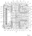
- each of the turntables 11 a positive Locking device assigned to the workpiece holder 1 through which, during the processing, the respectively tense Workpiece 14 in a predetermined angle of rotation position lockable in the correct position relative to the workpiece carrier is.
- This mechanical locking device is best from Figures 5, 6 and 7 to be seen.
- the receiving plate 13 of each of the rotary tables 11 is with the bearing pin 20 of its connecting element 19 in the associated bearing bore 21 of the workpiece carrier 1 screwed piston 22 not only rotatable sealed, but also axially displaceable to a limited extent.
- On its underside is carried on a workpiece carrier 1 facing ring surface, adjoining the toothed ring 25a on the inside, a plan gear in the form of a so-called Hirth serration 45, the first locking device on the a first locking part representing receiving plate 13 forms.
- the receiving plate 13 is opposite at a distance a coaxial toothed ring 46 is screwed onto the workpiece carrier 1, the one facing the receiving plate 13 Face a second face gear in the form of a second Hirth toothing 46a carries, the second locking means on the one serving as the second locking element Toothed ring 46 forms.
- the tooth pitches of the two Hirth gears 45, 46a are different from each other.
- a third locking part arranged in the form of a dividing disc 47, the encloses a ring cylinder 48 which is sealed and axial is slidably mounted on the cylinder liner 24 and bounded with a circumferential cylinder space 49.
- a ring piston 50 rigidly connected to workpiece holder 1, on the inner surface of the inner cylinder liner 24 is slidably guided and the is surrounded on the outside by the ring cylinder 48.
- the ring cylinder 48 is against the outer surface of the annular piston 50 sealed and bounded with the free face of the Annular piston 50 an annular cylinder space 51st
- the index plate 47 is connected to the ring cylinder 48 in Corresponding groove-shaped ball receptacles used driving balls 52 rotatable, but axially immovably connected. It bears on its flat surfaces lying one against the other two coaxial Hirth gears arranged in ring areas 53, 54, the shape and tooth pitch of each opposite Hirth teeth 45 or 46a on the receiving plate 13 or the toothed ring 46 corresponds.
- the the Form teeth 45, 46a associated teeth 53, 54 Locking means on the third locking part performing index plate 47.
- the cylinder spaces 23, 49, 51 of the cylinder liner 24 and the ring cylinder 48 formed lifting cylinder assembly are suitable, trained in the workpiece holder 1
- the Hirth teeth 53 on the clamping plate 13 facing Top of the index plate 47 - and the associated one Hirth teeth 45 on the underside of the mounting plate 13 - a tooth pitch of 5 angular degrees corresponding to 72 Show teeth.
- the one on the opposite bottom of the index plate 47 arranged Hirth teeth 54 - and the associated Hirth toothing 46a on the toothed ring 45 - be corresponding with a tooth pitch of 4.5 degrees 80 teeth trained.
- the clamping plate 13 is over the Partial disk 47 and the toothed ring 46 form-fitting with the Workpiece holder 1 clamped, the Hirth serrations a high-precision positioning of the clamping plate 13 with respect ensure the workpiece carrier 1.
- each of the turntables 11 is pressurized again. Since the annular surface 24b effective in the axial direction the cylinder liner 24 is larger than that in the axial direction effective annular surface 48a in the cylinder space 49, the Clamping plate 13 to the longitudinal axis 3 of the workpiece carrier 1 directed inwards until the Hirth serrations 45 on the underside of the clamping plate 13 and 53 the top of the index plate 47 engage and the Clamping plate 13 fixed precisely against the workpiece carrier 1 lock.
- the clamping plate 13 is thus together with the Pitch 47 moves outward until the Hirth serrations 46a, 54 have completely disengaged, and the end position shown on the right in FIG is reached, on which the annular surface 24b of the annular space 23 the opposite annular surface 22a of the piston 22 abuts.
- the workpiece carrier 1 is about its longitudinal axis 3 by 4.5 angular degrees, i.e. a tooth division of the Hirth gears 54, 46 in the opposite direction to the rotated backwards by 5 degrees, whereupon the Hirth gears 54, 46a snap back into place become.
- the cylinder chamber 23 is again with Pressurized so that the cylinder spaces 23 and 51 are under the pressure of the print medium. Because the axis effective annular surface 24b in the cylinder space 23 is larger than the axially effective annular surface 51a in the Cylinder chamber 51 arises to the longitudinal axis 3 of the Workpiece carrier 1 directed movement of the receiving table 13 and the partial disk 47 coupled thereto, in the course of the Hirth gears 54 and 46a in each other grab and be locked against each other.
- the two described above in succession carried out two steps for setting a resulting new rotation angle position of the turntable 11 can also be carried out in reverse order, by first the Hirth gears 54, 46a in the described disengaged and the Clamping plate 13 by a predetermined angle of rotation value in a sense of rotation is twisted and then, after the locking of the index plate 47 with the toothed ring 46, the other Hirth gears 45 and 53 are unlocked, around the clamping plate 13 by the desired angular value twist and then lock.
- turntables 11 at the both explained successive rotary movements for Setting a new angular position in the same direction to rotate about the respective axis of rotation 12, i.e. that of the the two rotary movements, respectively, through the rotational angle values can be added to or subtracted from each other.
- the multiple clamping device contains an interrogation device, which determines whether all turntables 11 are working properly locked via their Hirth serrations 45, 53 and 54, 46a are.
- This query device has query elements in the form of cylindrical interrogation bolts or slides 55 on that in associated with the bearing bore 21 of the respective Rotary table 11 coaxial bores 56 of the workpiece carrier 1 are mounted for longitudinal displacement. Every query slider 55 lies on the end face on the journal 20 of the assigned receiving plate 13 and thus gropes its axial position with respect to the workpiece carrier 1. Everyone the interrogation slide 55 carries on it in the workpiece carrier 1 molded-in front face Link part 57, only up to the respective longitudinal median plane of the query slider is enough and only one quadrant occupies its circular end face.
- the backdrop part 57 is with a continuous semi-cylindrical Provide recess 58 (see Figure 5), the right angle runs to the longitudinal central axis of the query slide 55.
- all query sliders are 55, each in groups of four Query sliders, in the manner shown in FIG. 5 pushed together that their four semi-cylindrical Recesses 58 to a continuous cylindrical bore complement that at the intersection of the diagonals of the square Cross-sectional shape of the workpiece carrier 1 lies.
- Interrogation rod 61 is coupled to an actuating cylinder 62 and configured to interrogate the query bar 61 to adjust the workpiece body 1 axially.
- a at 630 indicated position sensor gives depending on the axial position of the query rod 61 to a control signal control of the CNC machining center.
- the locking means especially Hirth gears, with different Have angular divisions so that a practically arbitrary subdivision of the switching movement in angular increments.
- a big advantage The new jig is that it stands out characterized by a small space requirement, so that several these fixtures to a multiple fixture can be summarized, in which, as described, a plurality of rotary tables 11, on several levels distributed, arranged on a common workpiece carrier are. The one required for the positioning of the turntables Rotational movement is in the described embodiment for all rotary tables 11 from a rotating NC axis derived, resulting in a very economical solution results.
- the dividing discs 47 do not require their own additional ones Drive devices and control means associated therewith.
- the clamping device ensures a very precise and stable positioning of the workpieces, one Change the respective position in small angular increments (less than e.g. an angular degree) without further ado is possible.
- the simple, closed structure of the new clamping device also offers the prerequisite for use in critical areas, such as in metalworking, due to the action of coolants, oils, Grinding dust changing temperatures, chips and the like are common.
Landscapes
- Engineering & Computer Science (AREA)
- Mechanical Engineering (AREA)
- Machine Tool Units (AREA)
- Machine Tool Positioning Apparatuses (AREA)
- Jigs For Machine Tools (AREA)
- Drilling And Boring (AREA)
- Feeding Of Workpieces (AREA)
Abstract
Description
- Fig. 1
- eine Mehrfach-Spannvorrichtung gemäß der Erfindung in perspektivischer Darstellung,
- Fig. 2
- die Mehrfach-Spannvorrichtung nach Fig. 1 mit teilweise abgenommenen Drehtischen unter Veranschaulichung verschiedener Hirth-Verzahnungen, in einer entsprechenden perspektivischen Darstellung,
- Fig. 3
- die Mehrfach-Spannvorrichtung nach Fig. 1 im axialen Längsschnitt, in einer Seitenansicht, im Ausschnitt unter Veranschaulichung ihrer Antriebseinrichtung, in einem anderen Maßstab,
- Fig. 4
- die Mehrfach-Spannvorrichtung nach Fig. 1 im axialen Längsschnitt, in einer Seitenansicht, im Ausschnitt unter Veranschaulichung ihrer Abfrageinrichtung, in einem anderen Maßstab,
- Fig. 5
- die Mehrfach-Spannvorrichtung nach Fig. 1, geschnitten längs der Line V-V der Fig. 4 in einer Seitenansicht unter Veranschaulichung verschiedener Betriebszuständen der vier dargestellten Drehtische,
- Fig. 6
- die Mehrfach-Spannvorrichtung nach Fig. 1 im axialen Längsschnitt, in einer Seitenansicht, im Ausschnitt unter Veranschaulichung von zwei einander gegenüberliegenden Drehtischen, in einem anderen Maßstab und
- Fig. 7
- eine Hubzylinderanordnung der Mehrfach-Spannvorrichtung nach Figur 6, in einer entsprechenden Teilansicht und in einem anderen Maßstab.
Claims (16)
- Spannvorrichtung, insbesondere für mehrseitig zu bearbeitende Werkstücke, miteinem Werkstückträger (1),wenigstens einem zur Werkstückaufnahme eingerichteten Drehtisch (11), der an dem Werkstückträger (1), um eine Drehachse (12) drehbar gelagert isteiner dem Drehtisch (11) zugeordneten formschlüssigen Verriegelungseinrichtung an dem Werkstückträger, durch die der Drehtisch (11) in einer vorgegebenen Drehwinkelstellung relativ zu dem Werkstückträger (1) lagegenau verriegelbar ist, wobei die Verriegelungseinrichtung aufweist:wenigstens drei zueinander koaxiale Verriegelungsteile (13,47, 46), von denen ein erstes Verriegelungsteil (13) mit dem Drehtisch (11) und ein zweites Verriegelungsteil (46) mit dem Werkstückträger (1) jeweils fest verbunden ist und wenigstens ein drittes Verriegelungsteil (47) zwischen dem ersten (13) und dem zweiten Verriegelungsteil (46) angeordnet und bezüglich des Werkstückträgers (1) drehbar gelagert ist und alle Verriegelungsteile auf den einander zugewandten Planflächen jeweils paarweise miteinander zusammenwirkende Verriegelungsmittel (45,53; 46a,54) tragen, die durch eine axiale Relativbewegung der Verriegelungsteile zueinander in und außer Eingriff bringbar sind undBetätigungsmitteln, um die Verriegelungsmittel der Verrieglungsteile wahlweise derart in und außer Eingriff zu bringen, dass das wenigstens eine dritte Verriegelungsteil (47) über seine Verriegelungsmittel immer mit zumindest einem ihm benachbarten Verriegelungsteil verrastet gehalten bleibt.einer Antriebseinrichtung, die mit dem Drehtisch (11) gekuppelt ist und durch die der Drehtisch bei gelösten Verriegelungsmitteln um einen vorbestimmten Winkelwert um seine Drehachse (12) verdrehbar ist.
- Spannvorrichtung nach Anspruch 1, dadurch gekennzeichnet, dass die Verriegelungsmittel jeweils durch eine Hirth-Verzahnung (5,53; 46a,54) gebildet sind.
- Spannvorrichtung nach Anspruch 1 oder 2, dadurch gekennzeichnet, dass die Verriegelungsmittel (45) des ersten Verriegelungsteils (13) und die diesen zugeordneten Verriegelungsmittel (53) des zweiten Verriegelungsteil (47) eine andere Winkelteilung aufweisen wie die Verriegelungsmittel (46a) des zweiten Verriegelungsteils (46) und die dieser zugeordneten Verriegelungsmittel (54) des dritten Verriegelungsteils (47).
- Spannvorrichtung nach Anspruch 1 oder 2, dadurch gekennzeichnet, dass das wenigstens eine dritte Verriegelungsteil (47) lose zwischen dem ersten und dem zweiten Verriegelungsteil (13,46) gelagert ist.
- Spannvorrichtung nach Anspruch 1, dadurch gekennzeichnet, dass der Drehtisch (11) eine Stirnverzahnung (25) aufweist oder mit diese drehfest verbunden ist, über die er mit Getriebemitteln (26,31) der Antriebseinrichtung (33) formschlüssig gekuppelt ist.
- Spannvorrichtung nach einem der vorhergehenden Ansprüche, dadurch gekennzeichnet, dass die Betätigungsmittel eine Hubeinrichtung aufweisen, durch die das erste und/oder zweite Verriegelungsteil (13,46) und/oder das wenigstens eine dritte Verriegelungsteil (47) relativ zueinander axial verstellbar sind.
- Spannvorrichtung nach Anspruch 6, dadurch gekennzeichnet, dass die Hubeinrichtung druckmediumsbetätigt ist.
- Spannvorrichtung nach Anspruch 7, dadurch gekennzeichnet, dass die Hubeinrichtung wenigstens zwei zu der Drehachse (12) koaxiale, mit Druckmittel beaufschlagbare Hubzylinder (24,48) aufweist, die bezüglich des Werkstückträgers (1) axial verstellbar gelagert sind und von denen einer (24) mit dem ersten (13) oder dem zweiten (46) Verriegelungsteil und ein anderer (48) mit wenigstens einem dritten Verriegelungsteil (47) gekuppelt ist.
- Spannvorrichtung nach Anspruch 8, dadurch gekennzeichnet, dass der eine Hubzylinder (24) mit dem ersten (13) oder zweiten (45) Verriegelungsteil und der andere Hubzylinder (48) mit dem zugeordneten dritten Verriegelungsteil (47) jeweils drehbar, aber axial unverschieblich gekuppelt ist.
- Spannvorrichtung nach einem der vorhergehenden Ansprüche, dadurch gekennzeichnet, dass das wenigstens eine dritte Verriegelungsteil als Teilscheibe (47) ausgebildet ist, die auf den beiden einander gegenüberliegenden Planseiten jeweils ein Verriegelungsmittel (53,54) trägt.
- Spannvorrichtung nach einem der vorhergehenden Ansprüche, dadurch gekennzeichnet, dass das wenigstens eine dritte Verriegelungsteil (47) bei bezüglich des ersten oder des zweiten Verriegelungsteiles (13,46) gelöster Verriegelung mit dem jeweils anderen Verriegelungsteil verrastet oder verriegelt gehalten ist.
- Spannvorrichtung nach einem der vorhergehenden Ansprüche, dadurch gekennzeichnet, dass der Werkstückträger (1) im Querschnitt polygonal gestaltet ist und wenigstens zwei parallel zu seiner Längsachse verlaufende Aufspannflächen (2) trägt und das auf jeder Aufspannfläche wenigstens ein Drehtisch (11) angeordnet ist.
- Spannvorrichtung nach Anspruch 11, dadurch gekennzeichnet, dass auf jeder Aufspannfläche (2) des balkenartig ausgebildeten Werkstückträgers wenigstens zwei Drehtische (11) angeordnet sind, deren Drehachse (12) in einer gemeinsamen, die Längsmittelachse des Werkstückträgers enthaltenden Ebene liegen.
- Spannvorrichtung nach Anspruch 12 oder 13, dadurch gekennzeichnet, dass die Antriebseinrichtung eine für alle Drehtische (11) gemeinsame Antriebsquelle aufweist, mit der die Getriebemittel der Drehtische (11) formschlüssig gekuppelt sind.
- Spannvorrichtung nach Anspruch 14, dadurch gekennzeichnet, dass die gemeinsame Antriebsquelle ein zentrales Antriebszahnrad (33) aufweist mit dem die Getriebemittel in Eingriff stehen, dass der Werkstückträger (1) in Lagermitteln um seine Längsmittelachse (3) drehbar gelagert ist und dass das Antriebszahnrad (33) relativ zu den Lagermitteln drehbar fixierbar ist.
- Spannvorrichtung nach Anspruch 14, dadurch gekennzeichnet, dass die gemeinsame Antriebsquelle unabhängig von der Drehbewegung des Werkstückträgers (1) um dessen Längsachse (3) ansteuerbar ist.
Applications Claiming Priority (2)
| Application Number | Priority Date | Filing Date | Title |
|---|---|---|---|
| DE10044915A DE10044915B4 (de) | 2000-09-12 | 2000-09-12 | Spannvorrichtung, insbesondere für mehrseitig zu bearbeitende Werkstücke |
| DE10044915 | 2000-09-12 |
Publications (2)
| Publication Number | Publication Date |
|---|---|
| EP1186373A1 true EP1186373A1 (de) | 2002-03-13 |
| EP1186373B1 EP1186373B1 (de) | 2006-05-31 |
Family
ID=7655828
Family Applications (1)
| Application Number | Title | Priority Date | Filing Date |
|---|---|---|---|
| EP01119316A Expired - Lifetime EP1186373B1 (de) | 2000-09-12 | 2001-08-10 | Spannvorrichtung, insbesondere für mehrseitig zu bearbeitende Werkstücke |
Country Status (4)
| Country | Link |
|---|---|
| US (1) | US6629345B2 (de) |
| EP (1) | EP1186373B1 (de) |
| AT (1) | ATE327859T1 (de) |
| DE (2) | DE10044915B4 (de) |
Cited By (10)
| Publication number | Priority date | Publication date | Assignee | Title |
|---|---|---|---|---|
| CN103252663A (zh) * | 2013-04-19 | 2013-08-21 | 苏州弘远机械制造有限公司 | 一种主轴套粗加工治具及加工工艺 |
| CN103433782A (zh) * | 2013-08-31 | 2013-12-11 | 荆州市祥达机械制造有限公司 | 汽车电动转向器蜗轮蜗杆壳体专用四轴夹具 |
| CN104786082A (zh) * | 2015-04-24 | 2015-07-22 | 铁岭天河机械制造有限责任公司 | 汽车发动机调温器座加工卡具 |
| CN104889771A (zh) * | 2015-06-03 | 2015-09-09 | 济南大学 | 一种多工位柔性夹持工装 |
| WO2015168712A1 (de) * | 2014-05-07 | 2015-11-12 | Amann Girrbach Ag | Werkstückträger |
| CN105382630A (zh) * | 2015-12-02 | 2016-03-09 | 贵州汉诺威数控机床有限公司 | 一种多功能复合分度机构 |
| CN108890488A (zh) * | 2018-07-19 | 2018-11-27 | 李国理 | 一种加工与存取同步的多工位设备 |
| CN109128934A (zh) * | 2018-09-27 | 2019-01-04 | 杭州昌鼎机械有限公司 | 汽车电池盒部件机加工回转夹具 |
| CN113618433A (zh) * | 2021-08-26 | 2021-11-09 | 无锡迈泽科技有限公司 | 一种弯曲类异性件四轴加工工装 |
| CN115847115A (zh) * | 2023-02-28 | 2023-03-28 | 象山申达轿车配件有限公司 | 差速器壳体及夹具 |
Families Citing this family (19)
| Publication number | Priority date | Publication date | Assignee | Title |
|---|---|---|---|---|
| DE10233869B4 (de) * | 2002-07-25 | 2005-12-08 | Roland Huber | Nachrüstbarer Aufsatztisch für Werkstückbearbeitungsmaschinen |
| US7331093B2 (en) * | 2004-04-08 | 2008-02-19 | Dm2 Di Duina Gianfranco S.R.L. | Pieces hold-unit for workstations, transfer machines and like |
| CN100515663C (zh) * | 2006-03-10 | 2009-07-22 | 鸿富锦精密工业(深圳)有限公司 | 成型方法及夹具 |
| CN102642132A (zh) * | 2012-04-28 | 2012-08-22 | 苏州市达圣机械有限公司 | 一种机床加工中心的工作台 |
| CN102626868B (zh) * | 2012-04-28 | 2013-11-20 | 苏州市达圣机械有限公司 | 机床加工中心的工作台 |
| CN104802023B (zh) * | 2014-01-24 | 2017-06-13 | 富鼎电子科技(嘉善)有限公司 | 翻转装置 |
| EP2929979A1 (de) * | 2014-04-08 | 2015-10-14 | Etxe-Tar, S.A. | Werkzeugmaschine zur mechanischen Bearbeitung von Gestängen |
| KR101523364B1 (ko) * | 2015-02-10 | 2015-05-28 | 고재식 | 지그 조립체 및 이를 구비하는 가공장치 |
| CN106181507A (zh) * | 2015-05-07 | 2016-12-07 | 哈尔滨飞机工业集团有限责任公司 | 一种多面可旋转工装 |
| KR102093074B1 (ko) * | 2019-09-26 | 2020-05-26 | 이종규 | 화기용 브래킷 제조방법 |
| CN110814796A (zh) * | 2019-11-25 | 2020-02-21 | 天津亿金鑫金属制品有限公司 | 一种斜支撑顶头定位装置 |
| CN111215919B (zh) * | 2020-03-18 | 2025-02-28 | 珠海格力智能装备有限公司 | 工作台及具有其的机床 |
| CN112025350A (zh) * | 2020-08-20 | 2020-12-04 | 南京中车浦镇城轨车辆有限责任公司 | 一种多功能堆叠式工艺装置 |
| CN113231851B (zh) * | 2021-05-18 | 2022-03-11 | 衢州职业技术学院 | 一种数控机床主轴箱的加工系统及其加工工艺 |
| CN114633133B (zh) * | 2022-05-20 | 2022-08-09 | 四川仨川航空科技股份有限公司 | 一种飞机异形零件夹持辅助装置及其夹持方法 |
| KR102559939B1 (ko) * | 2022-09-15 | 2023-07-27 | 박웅각 | 클러치 샤프트용 지그 시스템 |
| CN116079153B (zh) * | 2023-02-15 | 2025-09-09 | 上海电气液压气动有限公司 | 一种马达盖的加工方法 |
| DE102023129241A1 (de) * | 2023-10-24 | 2025-04-24 | Zeroclamp Gmbh | Werkstückträger |
| CN117798853A (zh) * | 2024-01-19 | 2024-04-02 | 无锡禹田真空设备有限公司 | 一种用于流量计的自动夹紧夹具 |
Citations (4)
| Publication number | Priority date | Publication date | Assignee | Title |
|---|---|---|---|---|
| US3049032A (en) * | 1959-08-20 | 1962-08-14 | Bernard W Schabot | Rotary precision work holder |
| US3846912A (en) * | 1972-01-10 | 1974-11-12 | R Newbould | Indexing mechanism |
| US3908484A (en) * | 1973-03-22 | 1975-09-30 | Frederick I Degen | Dividing head |
| DE19840942C1 (de) * | 1998-09-08 | 2000-03-09 | Albeck Gmbh | Mehrfach-Spannvorrichtung |
Family Cites Families (10)
| Publication number | Priority date | Publication date | Assignee | Title |
|---|---|---|---|---|
| US3146640A (en) * | 1961-08-02 | 1964-09-01 | Michigan Tool Co | Indexing device |
| DE1962097C3 (de) * | 1969-12-11 | 1982-09-09 | Fibro Gmbh, 7102 Weinsberg | Rundschalttisch |
| US4353271A (en) * | 1980-05-15 | 1982-10-12 | A.G. Davis Gage And Engineering Co. | Multiple position rotary index table |
| US4380939A (en) * | 1980-07-01 | 1983-04-26 | Cameron Iron Works, Inc. | Rotary indexing table |
| US4463488A (en) * | 1981-03-17 | 1984-08-07 | A. G. Davis Gage & Engineering Co. | Indexing work table |
| CA1199050A (en) * | 1981-10-26 | 1986-01-07 | Daniel J. Pieczulewski | Rotary index table with fluid pressure preloaded bearings |
| DE3676078D1 (de) * | 1986-03-07 | 1991-01-17 | Chuang Kuo Huey | Getriebe eines revolverkopfes bestehend aus einer zwillingsscheibe fuer cnc-maschinen. |
| DE3817937A1 (de) * | 1988-05-26 | 1989-11-30 | Sauter Kg Feinmechanik | Werkzeugrevolver |
| US5450771A (en) * | 1993-06-16 | 1995-09-19 | Utica Enterprises, Inc. | Rotary index table assembly |
| US5682658A (en) * | 1996-03-04 | 1997-11-04 | Utica Enterprises, Inc. | Rotary index table assembly |
-
2000
- 2000-09-12 DE DE10044915A patent/DE10044915B4/de not_active Expired - Fee Related
-
2001
- 2001-08-10 DE DE50109930T patent/DE50109930D1/de not_active Expired - Fee Related
- 2001-08-10 EP EP01119316A patent/EP1186373B1/de not_active Expired - Lifetime
- 2001-08-10 AT AT01119316T patent/ATE327859T1/de not_active IP Right Cessation
- 2001-09-10 US US09/949,609 patent/US6629345B2/en not_active Expired - Fee Related
Patent Citations (4)
| Publication number | Priority date | Publication date | Assignee | Title |
|---|---|---|---|---|
| US3049032A (en) * | 1959-08-20 | 1962-08-14 | Bernard W Schabot | Rotary precision work holder |
| US3846912A (en) * | 1972-01-10 | 1974-11-12 | R Newbould | Indexing mechanism |
| US3908484A (en) * | 1973-03-22 | 1975-09-30 | Frederick I Degen | Dividing head |
| DE19840942C1 (de) * | 1998-09-08 | 2000-03-09 | Albeck Gmbh | Mehrfach-Spannvorrichtung |
Cited By (17)
| Publication number | Priority date | Publication date | Assignee | Title |
|---|---|---|---|---|
| CN103252663A (zh) * | 2013-04-19 | 2013-08-21 | 苏州弘远机械制造有限公司 | 一种主轴套粗加工治具及加工工艺 |
| CN103433782A (zh) * | 2013-08-31 | 2013-12-11 | 荆州市祥达机械制造有限公司 | 汽车电动转向器蜗轮蜗杆壳体专用四轴夹具 |
| CN103433782B (zh) * | 2013-08-31 | 2015-08-26 | 荆州市祥达机械制造有限公司 | 汽车电动转向器蜗轮蜗杆壳体专用四轴夹具 |
| US11224919B2 (en) | 2014-05-07 | 2022-01-18 | Amann Girrbach Ag | Method for correcting an axial position of a workpiece support |
| WO2015168712A1 (de) * | 2014-05-07 | 2015-11-12 | Amann Girrbach Ag | Werkstückträger |
| EP4039224A1 (de) * | 2014-05-07 | 2022-08-10 | Amann Girrbach AG | Werkstückträger |
| CN104786082A (zh) * | 2015-04-24 | 2015-07-22 | 铁岭天河机械制造有限责任公司 | 汽车发动机调温器座加工卡具 |
| CN104786082B (zh) * | 2015-04-24 | 2016-11-23 | 铁岭天河机械制造有限责任公司 | 汽车发动机调温器座加工卡具 |
| CN104889771A (zh) * | 2015-06-03 | 2015-09-09 | 济南大学 | 一种多工位柔性夹持工装 |
| CN105382630B (zh) * | 2015-12-02 | 2017-11-07 | 贵州汉诺威数控机床有限公司 | 一种多功能复合分度机构 |
| CN105382630A (zh) * | 2015-12-02 | 2016-03-09 | 贵州汉诺威数控机床有限公司 | 一种多功能复合分度机构 |
| CN108890488A (zh) * | 2018-07-19 | 2018-11-27 | 李国理 | 一种加工与存取同步的多工位设备 |
| CN109128934A (zh) * | 2018-09-27 | 2019-01-04 | 杭州昌鼎机械有限公司 | 汽车电池盒部件机加工回转夹具 |
| CN109128934B (zh) * | 2018-09-27 | 2019-09-24 | 杭州昌鼎机械有限公司 | 汽车电池盒部件机加工回转夹具 |
| CN113618433A (zh) * | 2021-08-26 | 2021-11-09 | 无锡迈泽科技有限公司 | 一种弯曲类异性件四轴加工工装 |
| CN115847115A (zh) * | 2023-02-28 | 2023-03-28 | 象山申达轿车配件有限公司 | 差速器壳体及夹具 |
| CN115847115B (zh) * | 2023-02-28 | 2023-05-23 | 象山申达轿车配件有限公司 | 差速器壳体及夹具 |
Also Published As
| Publication number | Publication date |
|---|---|
| DE10044915A1 (de) | 2002-04-18 |
| US6629345B2 (en) | 2003-10-07 |
| DE50109930D1 (de) | 2006-07-06 |
| EP1186373B1 (de) | 2006-05-31 |
| US20020069498A1 (en) | 2002-06-13 |
| DE10044915B4 (de) | 2007-07-26 |
| ATE327859T1 (de) | 2006-06-15 |
Similar Documents
| Publication | Publication Date | Title |
|---|---|---|
| EP1186373B1 (de) | Spannvorrichtung, insbesondere für mehrseitig zu bearbeitende Werkstücke | |
| DE19840942C1 (de) | Mehrfach-Spannvorrichtung | |
| EP0596956B1 (de) | Werkzeugrevolver für eine werkzeugmaschine, insbesondere eine drehmaschine | |
| DE3730561C1 (de) | Werkzeugrevolver | |
| DE69229754T2 (de) | Werkzeugmaschine zur Verbundbearbeitung | |
| DE102007008837A1 (de) | Kupplungseinrichtung für Werkzeughalter oder Werkstückspanneinrichtungen | |
| DE19740379A1 (de) | Werkzeugrevolver für eine Werkzeugmaschine sowie Drehmaschine mit einem solchen Werkzeugrevolver | |
| DE2814013A1 (de) | Baueinheit mit einem drehbaren arbeitstisch und einer schrittschalt- steuereinrichtung | |
| EP0989922B1 (de) | Montage- oder fertigungsautomat und arbeitsstation für einen solchen automaten | |
| DE3209512A1 (de) | Rundschalttisch | |
| DE2308984C2 (de) | Schalttisch-Automat | |
| DE69527730T2 (de) | Rotierender bewegungsmechanismus | |
| DE3941480C2 (de) | ||
| DE69107639T2 (de) | Antriebsvorrichtung für Werkzeuge und Revolverkopf. | |
| DE3990008C1 (de) | ||
| DE2949709B1 (de) | Einrichtung zum Indexieren und Zentrieren bezueglich der Fraesspindelachse eines Winkelfraeskopfes an der Bodenplatte eines Fraesspindelstockes | |
| DE3619999C2 (de) | ||
| DE4235095C2 (de) | Werkzeugrevolver | |
| DE4006057A1 (de) | Vorsatzteil-anbringungsmechanismus bei einer werkzeugmaschine | |
| DE2840129A1 (de) | Befestigungsvorrichtung zum halten eines werkstuecks an einer werkzeugmaschine | |
| DE2129515B2 (de) | Schalttellermaschine | |
| DE3231782A1 (de) | Nc-gesteuerte revolver-drehmaschine | |
| DE4135735C1 (de) | ||
| DE10351694B4 (de) | Vorrichtung zum Erzeugen einer Klemmung | |
| DE3539471C1 (de) | Vorrichtung zum Verschwenken einer Werkzeugaufnahmevorrichtung, insbesondere eines Winkelfräskopfes, am freien (unteren) Ende eines Frässpindelstockes |
Legal Events
| Date | Code | Title | Description |
|---|---|---|---|
| PUAI | Public reference made under article 153(3) epc to a published international application that has entered the european phase |
Free format text: ORIGINAL CODE: 0009012 |
|
| AK | Designated contracting states |
Kind code of ref document: A1 Designated state(s): AT BE CH CY DE DK ES FI FR GB GR IE IT LI LU MC NL PT SE TR Kind code of ref document: A1 Designated state(s): AT CH DE FR GB IT LI |
|
| AX | Request for extension of the european patent |
Free format text: AL;LT;LV;MK;RO;SI |
|
| 17P | Request for examination filed |
Effective date: 20020531 |
|
| AKX | Designation fees paid |
Free format text: AT CH DE FR GB IT LI |
|
| GRAP | Despatch of communication of intention to grant a patent |
Free format text: ORIGINAL CODE: EPIDOSNIGR1 |
|
| GRAS | Grant fee paid |
Free format text: ORIGINAL CODE: EPIDOSNIGR3 |
|
| GRAA | (expected) grant |
Free format text: ORIGINAL CODE: 0009210 |
|
| AK | Designated contracting states |
Kind code of ref document: B1 Designated state(s): AT CH DE FR GB IT LI |
|
| REG | Reference to a national code |
Ref country code: CH Ref legal event code: EP Ref country code: GB Ref legal event code: FG4D Free format text: NOT ENGLISH |
|
| REG | Reference to a national code |
Ref country code: CH Ref legal event code: NV Representative=s name: KIRKER & CIE SA |
|
| REF | Corresponds to: |
Ref document number: 50109930 Country of ref document: DE Date of ref document: 20060706 Kind code of ref document: P |
|
| PGFP | Annual fee paid to national office [announced via postgrant information from national office to epo] |
Ref country code: AT Payment date: 20060816 Year of fee payment: 6 |
|
| GBT | Gb: translation of ep patent filed (gb section 77(6)(a)/1977) |
Effective date: 20060830 |
|
| ET | Fr: translation filed | ||
| PLBE | No opposition filed within time limit |
Free format text: ORIGINAL CODE: 0009261 |
|
| STAA | Information on the status of an ep patent application or granted ep patent |
Free format text: STATUS: NO OPPOSITION FILED WITHIN TIME LIMIT |
|
| 26N | No opposition filed |
Effective date: 20070301 |
|
| PG25 | Lapsed in a contracting state [announced via postgrant information from national office to epo] |
Ref country code: AT Free format text: LAPSE BECAUSE OF NON-PAYMENT OF DUE FEES Effective date: 20070810 |
|
| PGFP | Annual fee paid to national office [announced via postgrant information from national office to epo] |
Ref country code: CH Payment date: 20080814 Year of fee payment: 8 Ref country code: DE Payment date: 20080831 Year of fee payment: 8 |
|
| PGFP | Annual fee paid to national office [announced via postgrant information from national office to epo] |
Ref country code: FR Payment date: 20080813 Year of fee payment: 8 Ref country code: IT Payment date: 20080823 Year of fee payment: 8 |
|
| PGFP | Annual fee paid to national office [announced via postgrant information from national office to epo] |
Ref country code: GB Payment date: 20080821 Year of fee payment: 8 |
|
| REG | Reference to a national code |
Ref country code: CH Ref legal event code: PL |
|
| GBPC | Gb: european patent ceased through non-payment of renewal fee |
Effective date: 20090810 |
|
| PG25 | Lapsed in a contracting state [announced via postgrant information from national office to epo] |
Ref country code: CH Free format text: LAPSE BECAUSE OF NON-PAYMENT OF DUE FEES Effective date: 20090831 Ref country code: LI Free format text: LAPSE BECAUSE OF NON-PAYMENT OF DUE FEES Effective date: 20090831 |
|
| REG | Reference to a national code |
Ref country code: FR Ref legal event code: ST Effective date: 20100430 |
|
| PG25 | Lapsed in a contracting state [announced via postgrant information from national office to epo] |
Ref country code: FR Free format text: LAPSE BECAUSE OF NON-PAYMENT OF DUE FEES Effective date: 20090831 Ref country code: DE Free format text: LAPSE BECAUSE OF NON-PAYMENT OF DUE FEES Effective date: 20100302 |
|
| PG25 | Lapsed in a contracting state [announced via postgrant information from national office to epo] |
Ref country code: GB Free format text: LAPSE BECAUSE OF NON-PAYMENT OF DUE FEES Effective date: 20090810 |
|
| PG25 | Lapsed in a contracting state [announced via postgrant information from national office to epo] |
Ref country code: IT Free format text: LAPSE BECAUSE OF NON-PAYMENT OF DUE FEES Effective date: 20090810 |