EP1186767A2 - Exhaust gas recirculation system for internal combustion engine - Google Patents

Exhaust gas recirculation system for internal combustion engine Download PDF

Info

Publication number
EP1186767A2
EP1186767A2 EP01121561A EP01121561A EP1186767A2 EP 1186767 A2 EP1186767 A2 EP 1186767A2 EP 01121561 A EP01121561 A EP 01121561A EP 01121561 A EP01121561 A EP 01121561A EP 1186767 A2 EP1186767 A2 EP 1186767A2
Authority
EP
European Patent Office
Prior art keywords
egr
gas
passage
internal combustion
combustion engine
Prior art date
Legal status (The legal status is an assumption and is not a legal conclusion. Google has not performed a legal analysis and makes no representation as to the accuracy of the status listed.)
Withdrawn
Application number
EP01121561A
Other languages
German (de)
French (fr)
Other versions
EP1186767A3 (en
Inventor
Masahito Toyota Jidosha Kabushiki Kaisha Shibata
Yasuhiko Toyota Jidosha Kabushiki Kaisha Otsubo
Sadanobu Toyota Industries Corporation Shimizu
Current Assignee (The listed assignees may be inaccurate. Google has not performed a legal analysis and makes no representation or warranty as to the accuracy of the list.)
Toyota Motor Corp
Original Assignee
Toyota Motor Corp
Priority date (The priority date is an assumption and is not a legal conclusion. Google has not performed a legal analysis and makes no representation as to the accuracy of the date listed.)
Filing date
Publication date
Application filed by Toyota Motor Corp filed Critical Toyota Motor Corp
Publication of EP1186767A2 publication Critical patent/EP1186767A2/en
Publication of EP1186767A3 publication Critical patent/EP1186767A3/en
Withdrawn legal-status Critical Current

Links

Images

Classifications

    • FMECHANICAL ENGINEERING; LIGHTING; HEATING; WEAPONS; BLASTING
    • F02COMBUSTION ENGINES; HOT-GAS OR COMBUSTION-PRODUCT ENGINE PLANTS
    • F02MSUPPLYING COMBUSTION ENGINES IN GENERAL WITH COMBUSTIBLE MIXTURES OR CONSTITUENTS THEREOF
    • F02M26/00Engine-pertinent apparatus for adding exhaust gases to combustion-air, main fuel or fuel-air mixture, e.g. by exhaust gas recirculation [EGR] systems
    • F02M26/13Arrangement or layout of EGR passages, e.g. in relation to specific engine parts or for incorporation of accessories
    • F02M26/34Arrangement or layout of EGR passages, e.g. in relation to specific engine parts or for incorporation of accessories with compressors, turbines or the like in the recirculation passage
    • FMECHANICAL ENGINEERING; LIGHTING; HEATING; WEAPONS; BLASTING
    • F02COMBUSTION ENGINES; HOT-GAS OR COMBUSTION-PRODUCT ENGINE PLANTS
    • F02MSUPPLYING COMBUSTION ENGINES IN GENERAL WITH COMBUSTIBLE MIXTURES OR CONSTITUENTS THEREOF
    • F02M26/00Engine-pertinent apparatus for adding exhaust gases to combustion-air, main fuel or fuel-air mixture, e.g. by exhaust gas recirculation [EGR] systems
    • F02M26/02EGR systems specially adapted for supercharged engines
    • F02M26/04EGR systems specially adapted for supercharged engines with a single turbocharger
    • F02M26/06Low pressure loops, i.e. wherein recirculated exhaust gas is taken out from the exhaust downstream of the turbocharger turbine and reintroduced into the intake system upstream of the compressor
    • FMECHANICAL ENGINEERING; LIGHTING; HEATING; WEAPONS; BLASTING
    • F02COMBUSTION ENGINES; HOT-GAS OR COMBUSTION-PRODUCT ENGINE PLANTS
    • F02MSUPPLYING COMBUSTION ENGINES IN GENERAL WITH COMBUSTIBLE MIXTURES OR CONSTITUENTS THEREOF
    • F02M26/00Engine-pertinent apparatus for adding exhaust gases to combustion-air, main fuel or fuel-air mixture, e.g. by exhaust gas recirculation [EGR] systems
    • F02M26/13Arrangement or layout of EGR passages, e.g. in relation to specific engine parts or for incorporation of accessories
    • F02M26/22Arrangement or layout of EGR passages, e.g. in relation to specific engine parts or for incorporation of accessories with coolers in the recirculation passage
    • F02M26/23Layout, e.g. schematics
    • F02M26/28Layout, e.g. schematics with liquid-cooled heat exchangers
    • FMECHANICAL ENGINEERING; LIGHTING; HEATING; WEAPONS; BLASTING
    • F02COMBUSTION ENGINES; HOT-GAS OR COMBUSTION-PRODUCT ENGINE PLANTS
    • F02MSUPPLYING COMBUSTION ENGINES IN GENERAL WITH COMBUSTIBLE MIXTURES OR CONSTITUENTS THEREOF
    • F02M26/00Engine-pertinent apparatus for adding exhaust gases to combustion-air, main fuel or fuel-air mixture, e.g. by exhaust gas recirculation [EGR] systems
    • F02M26/13Arrangement or layout of EGR passages, e.g. in relation to specific engine parts or for incorporation of accessories
    • F02M26/22Arrangement or layout of EGR passages, e.g. in relation to specific engine parts or for incorporation of accessories with coolers in the recirculation passage
    • F02M26/29Constructional details of the coolers, e.g. pipes, plates, ribs, insulation or materials
    • F02M26/30Connections of coolers to other devices, e.g. to valves, heaters, compressors or filters; Coolers characterised by their location on the engine
    • FMECHANICAL ENGINEERING; LIGHTING; HEATING; WEAPONS; BLASTING
    • F02COMBUSTION ENGINES; HOT-GAS OR COMBUSTION-PRODUCT ENGINE PLANTS
    • F02MSUPPLYING COMBUSTION ENGINES IN GENERAL WITH COMBUSTIBLE MIXTURES OR CONSTITUENTS THEREOF
    • F02M26/00Engine-pertinent apparatus for adding exhaust gases to combustion-air, main fuel or fuel-air mixture, e.g. by exhaust gas recirculation [EGR] systems
    • F02M26/13Arrangement or layout of EGR passages, e.g. in relation to specific engine parts or for incorporation of accessories
    • F02M26/14Arrangement or layout of EGR passages, e.g. in relation to specific engine parts or for incorporation of accessories in relation to the exhaust system
    • F02M26/15Arrangement or layout of EGR passages, e.g. in relation to specific engine parts or for incorporation of accessories in relation to the exhaust system in relation to engine exhaust purifying apparatus
    • FMECHANICAL ENGINEERING; LIGHTING; HEATING; WEAPONS; BLASTING
    • F02COMBUSTION ENGINES; HOT-GAS OR COMBUSTION-PRODUCT ENGINE PLANTS
    • F02MSUPPLYING COMBUSTION ENGINES IN GENERAL WITH COMBUSTIBLE MIXTURES OR CONSTITUENTS THEREOF
    • F02M26/00Engine-pertinent apparatus for adding exhaust gases to combustion-air, main fuel or fuel-air mixture, e.g. by exhaust gas recirculation [EGR] systems
    • F02M26/50Arrangements or methods for preventing or reducing deposits, corrosion or wear caused by impurities

Definitions

  • the invention relates to an EGR (Exhaust Gas Recirculation) system for an internal combustion engine which is operable to recirculate at least a portion of an exhaust gas from an exhaust system to an intake air system of the engine, for the purpose of reducing nitrogen oxides (NOx) emissions.
  • EGR exhaust Gas Recirculation
  • Exhaust gas recirculation is performed as one of conventional techniques for purifying exhaust gas discharged from an internal combustion engine for a motor vehicle.
  • EGR Exhaust gas recirculation
  • at least a portion of the exhaust gas containing CO 2 which has a heat capacity larger than that of N 2 in the atmosphere, is reintroduced into a combustion chamber of the engine so as to lower a combustion temperature and, thus, to decrease an amount of nitrogen oxides (NOx) produced by the combustion.
  • the EGR technique is widely used for reducing NOx emissions in diesel engines in which combustion is performed in the presence of excessive air.
  • the EGR is likely to increase an amount of smoke emitted in the exhaust gas.
  • the engine is provided with an EGR system including an exhaust gas recirculation passage (EGR passage) for communication between an exhaust passage and an intake air passage, and an EGR valve disposed in the EGR passage.
  • EGR passage exhaust gas recirculation passage
  • the operation of the EGR system is controllable by suitably opening and closing the EGR valve.
  • the EGR system In the EGR system, at least a portion of the exhaust gas is reintroduced into an intake air of the engine as described above. Reintroducing the expanded exhaust gas at a high temperature into the intake air may decrease an amount of new air fed to the engine, and increase the combustion chamber temperature. As a result, the amount of NOx cannot be sufficiently reduced, and the amount of smoke is increased.
  • the aforementioned problem may be solved by providing the EGR system with an EGR cooler adapted to cool the exhaust gas flowing from the exhaust passage to the intake air.
  • the exhaust gas flowing from the exhaust passage to be reintroduced into the intake air is referred to as an "EGR gas".
  • the EGR system is operable to reintroduce the EGR gas into the intake air with the aid of a pressure difference between an exhaust pressure and an intake pressure.
  • the EGR cooler disposed in the EGR passage serves to resist the EGR gas flowing through the EGR passage, thus decreasing the flow rate of the EGR gas.
  • the pressure difference therebetween is reduced. In this case, the reduction of the pressure difference by the EGR cooler reaches the level that cannot be ignored.
  • the EGR is required to be performed even at a high intake air pressure during a high-load engine operation. Therefore, the EGR system generally needs to take a measure such that a sufficient pressure difference between the exhaust pressure and the intake pressure can be ensured.
  • the EGR system it is further required to purify the EGR gas so as to prevent clogging of the EGR valve, EGR cooler and compressor of the turbocharger, and contamination of the inside of the internal combustion engine.
  • EGR exhaust gas recirculation
  • the principle of the invention provides an EGR system for an internal combustion engine provided with cooling means disposed in an EGR passage, for cooling an EGR gas, an EGR-gas compressor which is disposed in the EGR passage upstream of the cooling means and is operable to compress the EGR gas, an EGR-gas turbine which is disposed in the EGR passage downstream of the cooling means and is operable to expand the EGR gas, and driving means for driving the EGR-gas compressor and the EGR-gas turbine.
  • the EGR passage communicates an exhaust passage downstream of a turbine of a supercharger for the internal combustion engine with an intake passage upstream of a compressor of the supercharger.
  • the EGR passage communicates an exhaust passage downstream of a particulate filter with an intake passage upstream of a compressor of a supercharger for the internal combustion engine.
  • Fig. 1 schematically shows a diesel engine with a supercharger incorporating an EGR system according to the preferred embodiment of the invention.
  • the diesel engine includes an engine body 10 provided with a plurality of cylinders each performing combustion therein, and an intake air passage 20 for supplying an intake air required for the combustion to the engine body 10. Described in detail, the engine is provided with the intake air passage 20, an air cleaner 22, a compressor 24 of the supercharger, an intercooler 26, and an intake manifold 28.
  • the intake air supplied to the engine body 10 through the intake air passage 20 is filtered by the air cleaner 22, compressed by the compressor 24, cooled by the intercooler 26, and then introduced to the intake manifold 28.
  • the intake manifold 28 serves to deliver the intake air to the plurality of cylinders of the engine body 10.
  • An exhaust gas generated in each of the cylinders is discharged through an exhaust passage 30.
  • the exhaust passage 30 is connected with an exhaust manifold 32, a turbine 34 of the supercharger and a diesel particulate filter (DPF) 36.
  • the exhaust gas discharged from each cylinder is collected in the exhaust manifold 32.
  • the collected exhaust gas is forced to pass through the turbine 34 that is connected coaxially with the compressor 24, purified by the DPF 36, and then finally discharged.
  • the diesel engine is adapted to perform combustion in the presence of excessive air. Accordingly, emissions of HC(hydrocarbons) and CO(carbon monoxide) as incomplete combustion components are reduced. On the contrary, however, emissions of particulates and nitrogen oxides (NOx) produced by a reaction between nitrogen in the atmosphere and unburned oxygen are increased in the exhaust gas.
  • the emitted particulates are formed as a composite of black smoke (dry soot) as a major component, soluble organic fraction (SOF), sulfates (sulfate mists) and the like. Therefore the particulate-emission rate cannot be reduced by merely improving combustion capacity of the internal combustion engine. Then the DPF 36 is provided in the exhaust passage 30 to lower the particulate emission by trapping the particulates therein.
  • the diesel engine of the invention is equipped with an EGR system intended to reduce the NOx emissions.
  • the EGR system includes an EGR passage 40 extending between the exhaust passage 30 and the intake air passage 20 so as to circulate the exhaust gas for reintroducing a portion of the exhaust gas, i.e., an EGR gas to the intake air.
  • An EGR valve 42 is provided in the EGR passage 40 to adjust a flow rate of the EGR gas to be recirculated.
  • An EGR cooler 44 is also provided in the EGR passage 40 for cooling the EGR gas.
  • the EGR cooler 44 may be formed as a heat exchanger using cooling water.
  • the EGR gas temperature decreases to be lower than a temperature limit below which the mist is generated. Therefore, the EGR gas mist is generated in the EGR cooler 44 and the mist particles adhere to the inside thereof. As a result, the EGR cooler 44 of the EGR gas is clogged.
  • the aforementioned clogging problem may be solved by providing an EGR-gas compressor 46 in the EGR passage 40 upstream of the EGR cooler 44 so as to temporarily increase the temperature of the EGR gas flowing into the EGR cooler 44.
  • the EGR gas temperature is effectively kept higher than the limit temperature, thus reducing an amount of the mist particles of the EGR gas generated in the EGR cooler 44.
  • the EGR system of the present embodiment further includes an EGR-gas turbine 48 disposed in the EGR passage 40 downstream of the EGR cooler 44.
  • the EGR-gas turbine 48 is adapted to expand the EGR gas delivered from the EGR cooler 44. Referring to Fig. 2B, expanding the EGR gas may decrease the EGR-gas temperature to the degree corresponding to a temperature increment of the EGR-gas compressed by the EGR-gas compressor 24. Since the EGR-gas turbine 48 rotates at a high revolution speed, no clogging occurs.
  • the temperature of the EGR gas is increased by compressing the EGR gas in the EGR-gas compressor 46 so as to prevent generation of the mist particles in the EGR cooler 44.
  • the temperature increment of the EGR-gas compressed by the EGR-gas compressor 46 can be effectively compensated by a temperature decrement of the EGR-gas expanded by the EGR-gas turbine 48.
  • the EGR system of the present embodiment makes it possible to recirculate the EGR gas cooled by the EGR cooler 44 to the intake air passage 20. Therefore, volumetric efficiency of the engine can be enhanced, and output characteristics, fuel economy, and exhaust gas purifying capacity of the engine can be improved.
  • EGR-gas turbine 48 and the EGR-gas compressor 46 are coaxially disposed with each other and are mechanically driven by driving means 50 such that the EGR gas increasingly flows through the EGR passage 40 without using an intake air throttle valve nor exhaust throttle valve.
  • Fig. 3 shows a first embodiment of the driving means 50 for driving the EGR-gas compressor 46 and the EGR-gas turbine 48.
  • the driving means 50 at least one of rotating members of the internal combustion engine, e.g., camshaft, timing belt, pulley, is utilized to drive the EGR-gas compressor 46 and the EGR-gas turbine 48.
  • Fig. 4 shows a second embodiment of the driving means 50 in which the driving means 50 is embodied by utilizing a power of the exhaust gas discharged from the engine. Namely, rotation of the supercharger consisting of the turbine 34 and the compressor 24 is utilized to drive the EGR-gas compressor 46 and the EGR-gas turbine 48.
  • Fig 5 shows a third embodiment of the driving means 50 in which an electric motor independent of the internal combustion engine is utilized to drive the EGR-gas compressor 46 and the EGR-gas turbine 48.
  • Fig. 6 shows a fourth embodiment of the driving means 50 which is embodied by utilizing a lubrication system of the internal combustion engine. That is, the EGR-gas compressor 46 and the EGR-gas turbine 48 are driven by a power of oil jet.
  • the EGR technique provides a recirculation of the exhaust gas into the intake air, by utilizing a pressure difference between an exhaust pressure and an intake air pressure.
  • the EGR cooler 44 functions as a resistance to the EGR gas flowing through the EGR passage 40, and reduces the pressure difference between the exhaust pressure and the intake air pressure.
  • the EGR system of the present embodiment is arranged such that the EGR passage 40 extends in communication between the exhaust passage 30 downstream of the turbine 34 of the supercharger and the intake air passage 20 upstream of the compressor 24 of the supercharger, as is apparent from Fig. 1. Namely, the pressure of the portion downstream of the turbine 34 is lower than that of the portion upstream of the turbine 34.
  • the intake air passage upstream of the compressor 24 is at a low pressure corresponding to be the atmospheric pressure, making it possible to keep sufficient pressure difference. Therefore, the EGR system of the embodiment may be operated during a high-load engine operation at a high intake air pressure.
  • the EGR passage 40 extends in communication between the exhaust passage 30 downstream of the DPF 36 and the intake air passage 20 EGR-gas upstream of the compressor 24 of the supercharger. This arrangement makes it possible to perform recirculation of purified EGR gas, thus preventing conventionally experienced problems such as clogging of the EGR valve 42, the EGR cooler 44 and the compressor 24 of the supercharger, and contamination of the inside of the internal combustion engine.
  • the EGR system of the invention is capable of performing the EGR gas by preventing generation of the mist particles of the EGR gas in the EGR cooler, and is operable of performing a desired amount of EGR gas within a broader range of engine operating conditions including the high-load engine operation condition. Further, the EGR system of the invention makes it possible to recirculate purified EGR gases, thus preventing problems of clogging of the EGR system components and the internal combustion engine or the like.
  • the EGR system for an internal combustion engine includes a cooling means 44 disposed in an EGR passage 40 for cooling an EGR gas, an EGR-gas compressor 46 disposed in the EGR passage 40 upstream of the cooling means 44 for compressing the EGR gas, an EGR-gas turbine 48 disposed in the EGR passage 40 downstream of the cooling means 44 for expanding the EGR gas, and driving means 50 for driving the EGR-gas compressor and turbine 46,48.
  • the EGR passage 40 extends in communication between the exhaust passage 30 downstream of a turbine 34 of a supercharger for the engine and the intake air passage 20 upstream of a compressor 24 of the supercharger.
  • the EGR passage 40 is connected to a portion of the exhaust passage 30 downstream of the particulate filter 36.

Landscapes

  • Engineering & Computer Science (AREA)
  • Chemical & Material Sciences (AREA)
  • Combustion & Propulsion (AREA)
  • Mechanical Engineering (AREA)
  • General Engineering & Computer Science (AREA)
  • Exhaust-Gas Circulating Devices (AREA)
  • Supercharger (AREA)
  • Output Control And Ontrol Of Special Type Engine (AREA)

Abstract

An EGR system for an internal combustion engine includes a cooling means (44) disposed in an EGR passage (40) for cooling an EGR gas, an EGR-gas compressor (46) disposed in the EGR passage (40) upstream of the cooling means (44) for compressing the EGR gas, an EGR-gas turbine (48) disposed in the EGR passage (40) downstream of the cooling means (44) for expanding the EGR gas, and driving means (50) for driving the EGR-gas compressor and turbine (46),(48). The EGR passage (40) extends in communication between the exhaust passage (30) downstream of a turbine (34) of a supercharger for the engine and the intake air passage (20) upstream of a compressor (24) of the supercharger. When the EGR system is equipped with a diesel particulate filter (36), the EGR passage (40) is connected to a portion of the exhaust passage (30) downstream of the particulate filter (36).

Description

BACKGROUND OF THE INVENTION 1.Field of the Invention
The invention relates to an EGR (Exhaust Gas Recirculation) system for an internal combustion engine which is operable to recirculate at least a portion of an exhaust gas from an exhaust system to an intake air system of the engine, for the purpose of reducing nitrogen oxides (NOx) emissions.
2.Description of Related Art
Exhaust gas recirculation (EGR) is performed as one of conventional techniques for purifying exhaust gas discharged from an internal combustion engine for a motor vehicle. According to the EGR technique, at least a portion of the exhaust gas containing CO2, which has a heat capacity larger than that of N2 in the atmosphere, is reintroduced into a combustion chamber of the engine so as to lower a combustion temperature and, thus, to decrease an amount of nitrogen oxides (NOx) produced by the combustion. The EGR technique is widely used for reducing NOx emissions in diesel engines in which combustion is performed in the presence of excessive air. The EGR, however, is likely to increase an amount of smoke emitted in the exhaust gas. The engine is provided with an EGR system including an exhaust gas recirculation passage (EGR passage) for communication between an exhaust passage and an intake air passage, and an EGR valve disposed in the EGR passage. The operation of the EGR system is controllable by suitably opening and closing the EGR valve.
In the EGR system, at least a portion of the exhaust gas is reintroduced into an intake air of the engine as described above. Reintroducing the expanded exhaust gas at a high temperature into the intake air may decrease an amount of new air fed to the engine, and increase the combustion chamber temperature. As a result, the amount of NOx cannot be sufficiently reduced, and the amount of smoke is increased. The aforementioned problem may be solved by providing the EGR system with an EGR cooler adapted to cool the exhaust gas flowing from the exhaust passage to the intake air. Hereinafter, the exhaust gas flowing from the exhaust passage to be reintroduced into the intake air is referred to as an "EGR gas".
In the EGR cooler, however, the lower the temperature of the EGR gas becomes, the more a mist of the EGR gas is generated. Particles of the resultant mist adhere to the inside of the EGR cooler, and clog the EGR cooler. Particularly, in the state where the EGR gas is at a relatively lower temperature than usual, e.g., during a low-load engine operation, its temperature is further decreased in the EGR cooler. This may further promote clogging of the EGR cooler with the mist particles.
The EGR system is operable to reintroduce the EGR gas into the intake air with the aid of a pressure difference between an exhaust pressure and an intake pressure. In this respect, the EGR cooler disposed in the EGR passage serves to resist the EGR gas flowing through the EGR passage, thus decreasing the flow rate of the EGR gas. Particularly in the internal combustion engine with a supercharger for the engine, since the exhaust pressure is increased as well as the intake air pressure, the pressure difference therebetween is reduced. In this case, the reduction of the pressure difference by the EGR cooler reaches the level that cannot be ignored. Meanwhile, in order to satisfy the requirement of the recent trend of further improvement in the exhaust-gas purifying capacity of the engine, the EGR is required to be performed even at a high intake air pressure during a high-load engine operation. Therefore, the EGR system generally needs to take a measure such that a sufficient pressure difference between the exhaust pressure and the intake pressure can be ensured.
In the EGR system, it is further required to purify the EGR gas so as to prevent clogging of the EGR valve, EGR cooler and compressor of the turbocharger, and contamination of the inside of the internal combustion engine.
SUMMARY OF THE INVENTION
It is an object of the invention to provide an exhaust gas recirculation (EGR) system for an internal combustion engine, which is capable of reducing an amount of mist particles generated in an EGR cooler, allowing a large amount of EGR gas to be recirculated by keeping a pressure difference between an exhaust pressure and an intake air pressure within a broader range of engine operating conditions including a high-load engine operating condition, and permitting recirculation of purified EGR gas.
To accomplish the above and/or other objects, the principle of the invention provides an EGR system for an internal combustion engine provided with cooling means disposed in an EGR passage, for cooling an EGR gas, an EGR-gas compressor which is disposed in the EGR passage upstream of the cooling means and is operable to compress the EGR gas, an EGR-gas turbine which is disposed in the EGR passage downstream of the cooling means and is operable to expand the EGR gas, and driving means for driving the EGR-gas compressor and the EGR-gas turbine.
According to one preferred form of the invention, the EGR passage communicates an exhaust passage downstream of a turbine of a supercharger for the internal combustion engine with an intake passage upstream of a compressor of the supercharger.
According to another preferred form of the invention, the EGR passage communicates an exhaust passage downstream of a particulate filter with an intake passage upstream of a compressor of a supercharger for the internal combustion engine.
BRIEF DESCRIPTION OF THE DRAWINGS
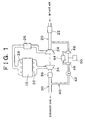
  • Fig. 1 is a schematic diagram of an internal combustion engine incorporating an EGR system according to one preferred embodiment of the invention;
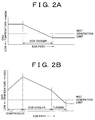
  • Fig. 2A is a graph showing a change in an EGR gas temperature in a conventional EGR system;
  • Fig. 2B is a graph showing a change in an EGR gas temperature in the EGR system of the invention;
  • Fig. 3 is a schematic diagram of a first embodiment of driving means for driving an EGR-gas compressor and an EGR-gas turbine incorporated in the EGR system of the invention;
  • Fig. 4 is a schematic diagram of a second embodiment of the driving means for driving the EGR-gas compressor and turbine incorporated in the EGR system of the invention;
  • Fig. 5 is a schematic diagram of a third embodiment of the driving means for driving the EGR-gas compressor and turbine incorporated in the EGR system of the invention; and
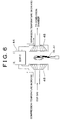
  • Fig. 6 is a schematic diagram of a fourth embodiment of the driving means for driving the EGR-gas compressor and turbine incorporated in the EGR system of the invention.
  • DETAILED DESCRIPTION OF PREFERRED EMBODIMENTS
    Preferred embodiments of the invention will be described with reference to the accompanying drawings.
    Fig. 1 schematically shows a diesel engine with a supercharger incorporating an EGR system according to the preferred embodiment of the invention. The diesel engine includes an engine body 10 provided with a plurality of cylinders each performing combustion therein, and an intake air passage 20 for supplying an intake air required for the combustion to the engine body 10. Described in detail, the engine is provided with the intake air passage 20, an air cleaner 22, a compressor 24 of the supercharger, an intercooler 26, and an intake manifold 28. The intake air supplied to the engine body 10 through the intake air passage 20 is filtered by the air cleaner 22, compressed by the compressor 24, cooled by the intercooler 26, and then introduced to the intake manifold 28. The intake manifold 28 serves to deliver the intake air to the plurality of cylinders of the engine body 10. An exhaust gas generated in each of the cylinders is discharged through an exhaust passage 30. Specifically, the exhaust passage 30 is connected with an exhaust manifold 32, a turbine 34 of the supercharger and a diesel particulate filter (DPF) 36. The exhaust gas discharged from each cylinder is collected in the exhaust manifold 32. The collected exhaust gas is forced to pass through the turbine 34 that is connected coaxially with the compressor 24, purified by the DPF 36, and then finally discharged.
    The diesel engine is adapted to perform combustion in the presence of excessive air. Accordingly, emissions of HC(hydrocarbons) and CO(carbon monoxide) as incomplete combustion components are reduced. On the contrary, however, emissions of particulates and nitrogen oxides (NOx) produced by a reaction between nitrogen in the atmosphere and unburned oxygen are increased in the exhaust gas. The emitted particulates are formed as a composite of black smoke (dry soot) as a major component, soluble organic fraction (SOF), sulfates (sulfate mists) and the like. Therefore the particulate-emission rate cannot be reduced by merely improving combustion capacity of the internal combustion engine. Then the DPF 36 is provided in the exhaust passage 30 to lower the particulate emission by trapping the particulates therein.
    The diesel engine of the invention is equipped with an EGR system intended to reduce the NOx emissions. The EGR system includes an EGR passage 40 extending between the exhaust passage 30 and the intake air passage 20 so as to circulate the exhaust gas for reintroducing a portion of the exhaust gas, i.e., an EGR gas to the intake air. An EGR valve 42 is provided in the EGR passage 40 to adjust a flow rate of the EGR gas to be recirculated. An EGR cooler 44 is also provided in the EGR passage 40 for cooling the EGR gas. In the present embodiment, the EGR cooler 44 may be formed as a heat exchanger using cooling water.
    In the conventional EGR system, as shown in Fig. 2A, when the EGR gas passes through the EGR cooler 44, the EGR gas temperature decreases to be lower than a temperature limit below which the mist is generated. Therefore, the EGR gas mist is generated in the EGR cooler 44 and the mist particles adhere to the inside thereof. As a result, the EGR cooler 44 of the EGR gas is clogged. The aforementioned clogging problem may be solved by providing an EGR-gas compressor 46 in the EGR passage 40 upstream of the EGR cooler 44 so as to temporarily increase the temperature of the EGR gas flowing into the EGR cooler 44. As is understood from the graph of Fig. 2B, when the EGR gas passes through the EGR cooler 44, the EGR gas temperature is effectively kept higher than the limit temperature, thus reducing an amount of the mist particles of the EGR gas generated in the EGR cooler 44.
    The EGR system of the present embodiment further includes an EGR-gas turbine 48 disposed in the EGR passage 40 downstream of the EGR cooler 44. The EGR-gas turbine 48 is adapted to expand the EGR gas delivered from the EGR cooler 44. Referring to Fig. 2B, expanding the EGR gas may decrease the EGR-gas temperature to the degree corresponding to a temperature increment of the EGR-gas compressed by the EGR-gas compressor 24. Since the EGR-gas turbine 48 rotates at a high revolution speed, no clogging occurs.
    In the EGR system of this embodiment, the temperature of the EGR gas is increased by compressing the EGR gas in the EGR-gas compressor 46 so as to prevent generation of the mist particles in the EGR cooler 44. The temperature increment of the EGR-gas compressed by the EGR-gas compressor 46 can be effectively compensated by a temperature decrement of the EGR-gas expanded by the EGR-gas turbine 48. In the end, the EGR system of the present embodiment makes it possible to recirculate the EGR gas cooled by the EGR cooler 44 to the intake air passage 20. Therefore, volumetric efficiency of the engine can be enhanced, and output characteristics, fuel economy, and exhaust gas purifying capacity of the engine can be improved. It should be appreciated that the EGR-gas turbine 48 and the EGR-gas compressor 46 are coaxially disposed with each other and are mechanically driven by driving means 50 such that the EGR gas increasingly flows through the EGR passage 40 without using an intake air throttle valve nor exhaust throttle valve.
    Fig. 3 shows a first embodiment of the driving means 50 for driving the EGR-gas compressor 46 and the EGR-gas turbine 48. According to the first embodiment of the driving means 50, at least one of rotating members of the internal combustion engine, e.g., camshaft, timing belt, pulley, is utilized to drive the EGR-gas compressor 46 and the EGR-gas turbine 48. Fig. 4 shows a second embodiment of the driving means 50 in which the driving means 50 is embodied by utilizing a power of the exhaust gas discharged from the engine. Namely, rotation of the supercharger consisting of the turbine 34 and the compressor 24 is utilized to drive the EGR-gas compressor 46 and the EGR-gas turbine 48.
    Fig 5 shows a third embodiment of the driving means 50 in which an electric motor independent of the internal combustion engine is utilized to drive the EGR-gas compressor 46 and the EGR-gas turbine 48. Fig. 6 shows a fourth embodiment of the driving means 50 which is embodied by utilizing a lubrication system of the internal combustion engine. That is, the EGR-gas compressor 46 and the EGR-gas turbine 48 are driven by a power of oil jet.
    Meanwhile, the EGR technique provides a recirculation of the exhaust gas into the intake air, by utilizing a pressure difference between an exhaust pressure and an intake air pressure. In this respect, the EGR cooler 44 functions as a resistance to the EGR gas flowing through the EGR passage 40, and reduces the pressure difference between the exhaust pressure and the intake air pressure. To compensate such decrease in the pressure difference, the EGR system of the present embodiment is arranged such that the EGR passage 40 extends in communication between the exhaust passage 30 downstream of the turbine 34 of the supercharger and the intake air passage 20 upstream of the compressor 24 of the supercharger, as is apparent from Fig. 1. Namely, the pressure of the portion downstream of the turbine 34 is lower than that of the portion upstream of the turbine 34. However, the intake air passage upstream of the compressor 24 is at a low pressure corresponding to be the atmospheric pressure, making it possible to keep sufficient pressure difference. Therefore, the EGR system of the embodiment may be operated during a high-load engine operation at a high intake air pressure.
    Referring to Fig. 1, the EGR passage 40 extends in communication between the exhaust passage 30 downstream of the DPF 36 and the intake air passage 20 EGR-gas upstream of the compressor 24 of the supercharger. This arrangement makes it possible to perform recirculation of purified EGR gas, thus preventing conventionally experienced problems such as clogging of the EGR valve 42, the EGR cooler 44 and the compressor 24 of the supercharger, and contamination of the inside of the internal combustion engine.
    As is understood from the foregoing description, the EGR system of the invention is capable of performing the EGR gas by preventing generation of the mist particles of the EGR gas in the EGR cooler, and is operable of performing a desired amount of EGR gas within a broader range of engine operating conditions including the high-load engine operation condition. Further, the EGR system of the invention makes it possible to recirculate purified EGR gases, thus preventing problems of clogging of the EGR system components and the internal combustion engine or the like.
    The EGR system for an internal combustion engine according to the present invention includes a cooling means 44 disposed in an EGR passage 40 for cooling an EGR gas, an EGR-gas compressor 46 disposed in the EGR passage 40 upstream of the cooling means 44 for compressing the EGR gas, an EGR-gas turbine 48 disposed in the EGR passage 40 downstream of the cooling means 44 for expanding the EGR gas, and driving means 50 for driving the EGR-gas compressor and turbine 46,48. The EGR passage 40 extends in communication between the exhaust passage 30 downstream of a turbine 34 of a supercharger for the engine and the intake air passage 20 upstream of a compressor 24 of the supercharger. When the EGR system is equipped with a diesel particulate filter 36, the EGR passage 40 is connected to a portion of the exhaust passage 30 downstream of the particulate filter 36.

    Claims (7)

    1. An EGR system for an internal combustion engine, comprising:
      cooling means (44), disposed in an EGR passage (40), for cooling an EGR gas;
      an EGR-gas compressor (46) which is disposed in the EGR passage (40) upstream of the cooling means (44) and is operable to compress the EGR gas;
      an EGR-gas turbine (48) which is disposed in the EGR passage (40) downstream of the cooling means (44) and is operable to expand the EGR gas; and
      driving means (50) for driving the EGR-gas compressor (46) and the EGR-gas turbine (48).
    2. An EGR system according to claim 1, wherein the EGR passage (40) communicates an exhaust passage (30) downstream of a turbine (34) of a supercharger for the internal combustion engine with an intake passage (20) upstream of a compressor (24) of the supercharger.
    3. An EGR system according to claim 1 or 2, wherein the EGR passage (40) communicates an exhaust passage (30) downstream of a particulate filter (36) with an intake passage (20) upstream of a compressor (24) of a supercharger for the internal combustion engine.
    4. An EGR system according to any one of claims 1 to 3, wherein the driving means (50) is operatively connected to a rotating member of the internal combustion engine.
    5. An EGR system according to any one of claims 1 to 3, wherein the driving means (50) is operatively connected to a supercharger for the internal combustion engine.
    6. An EGR system according to any one of claims 1 to 3, wherein the driving means (50) comprises a motor that is provided independently of the internal combustion engine.
    7. An EGR system according to any one of claims 1 to 3, wherein the driving means (50) utilizes a lubrication system of the internal combustion engine.
    EP01121561A 2000-09-11 2001-09-10 Exhaust gas recirculation system for internal combustion engine Withdrawn EP1186767A3 (en)

    Applications Claiming Priority (2)

    Application Number Priority Date Filing Date Title
    JP2000275428A JP2002089375A (en) 2000-09-11 2000-09-11 EGR device for internal combustion engine
    JP2000275428 2000-09-11

    Publications (2)

    Publication Number Publication Date
    EP1186767A2 true EP1186767A2 (en) 2002-03-13
    EP1186767A3 EP1186767A3 (en) 2003-04-23

    Family

    ID=18761050

    Family Applications (1)

    Application Number Title Priority Date Filing Date
    EP01121561A Withdrawn EP1186767A3 (en) 2000-09-11 2001-09-10 Exhaust gas recirculation system for internal combustion engine

    Country Status (2)

    Country Link
    EP (1) EP1186767A3 (en)
    JP (1) JP2002089375A (en)

    Cited By (17)

    * Cited by examiner, † Cited by third party
    Publication number Priority date Publication date Assignee Title
    FR2840648A1 (en) * 2002-06-11 2003-12-12 Inst Francais Du Petrole Device for control of exhaust gas recirculation for diesel engine comprises pipe and valve connected downstream of turbine and upstream of compressor
    WO2004044412A1 (en) 2002-11-13 2004-05-27 Honeywell International Inc. Dual and hybrid egr systems for use with turbocharged engine
    GB2386397B (en) * 2000-11-28 2005-02-16 Detroit Diesel Corp Electronic controlled engine exhaust treatment system to reduce NOx emissions
    US7013879B2 (en) 2003-11-17 2006-03-21 Honeywell International, Inc. Dual and hybrid EGR systems for use with turbocharged engine
    DE102004061028A1 (en) * 2004-12-18 2006-07-06 Pierburg Gmbh Exhaust gas recirculation system
    US7296403B2 (en) 2005-11-03 2007-11-20 Ford Global Technologies, Llc Dual walled particular filter for transporting filtered exhaust to a compressor of a diesel engine turbocharger
    EP1870590A1 (en) * 2006-06-22 2007-12-26 C.R.F. Società Consortile per Azioni Internal combustion engine with a pump for exhaust gas recirculation
    US7571608B2 (en) * 2005-11-28 2009-08-11 General Electric Company Turbocharged engine system and method of operation
    EP2108807A1 (en) 2008-04-12 2009-10-14 Pierburg GmbH Exhaust gas recirculation device for an internal combustion engine
    GB2459694A (en) * 2008-05-01 2009-11-04 Ford Global Tech Llc Exhaust gas recirculation
    US20110083641A1 (en) * 2009-10-13 2011-04-14 General Electric Company System and method for operating a turbocharged engine
    US8176736B2 (en) 2008-03-21 2012-05-15 Cummins Inc. EGR apparatuses, systems, and methods
    EP2505818A4 (en) * 2009-11-27 2014-01-01 Mitsubishi Heavy Ind Ltd Exhaust gas treatment device
    EP2639440A4 (en) * 2010-11-09 2016-10-05 Mitsubishi Heavy Ind Ltd DEVICE FOR PURIFYING EXHAUST GAS FROM AN ENGINE
    DE102015208957A1 (en) * 2015-05-15 2016-11-17 Ford Global Technologies, Llc Self-igniting internal combustion engine with turbocharging and exhaust gas recirculation
    US9989020B2 (en) 2015-05-15 2018-06-05 Ford Global Technologies, Llc Auto-ignition internal combustion engine with exhaust-gas turbocharging and exhaust-gas recirculation
    US20190186350A1 (en) * 2017-12-20 2019-06-20 John Manley McDonald Externally powered turbine for an internal combustion engine

    Families Citing this family (2)

    * Cited by examiner, † Cited by third party
    Publication number Priority date Publication date Assignee Title
    JP2007002668A (en) * 2003-07-01 2007-01-11 Tokudaiji Jidosha Bunka Kenkyusho:Kk Diesel engine exhaust purification device and control means
    JP5038992B2 (en) * 2008-08-19 2012-10-03 富士重工業株式会社 Diesel engine exhaust gas recirculation system

    Family Cites Families (4)

    * Cited by examiner, † Cited by third party
    Publication number Priority date Publication date Assignee Title
    JP3005776B2 (en) * 1991-09-10 2000-02-07 ヤンマーディーゼル株式会社 Exhaust gas recirculation system for diesel engine
    SE506125C2 (en) * 1994-12-08 1997-11-10 Scania Cv Ab Arrangements for redirecting exhaust gases in supercharged engines with parallel turbines
    JP2798901B2 (en) * 1995-07-27 1998-09-17 株式会社ディーゼルユナイテッド Exhaust gas recirculation device
    DE19603591C1 (en) * 1996-02-01 1997-03-06 Daimler Benz Ag Exhaust gas feedback system for turbocharged internal combustion engines

    Cited By (24)

    * Cited by examiner, † Cited by third party
    Publication number Priority date Publication date Assignee Title
    GB2386397B (en) * 2000-11-28 2005-02-16 Detroit Diesel Corp Electronic controlled engine exhaust treatment system to reduce NOx emissions
    FR2840648A1 (en) * 2002-06-11 2003-12-12 Inst Francais Du Petrole Device for control of exhaust gas recirculation for diesel engine comprises pipe and valve connected downstream of turbine and upstream of compressor
    WO2004044412A1 (en) 2002-11-13 2004-05-27 Honeywell International Inc. Dual and hybrid egr systems for use with turbocharged engine
    US7013879B2 (en) 2003-11-17 2006-03-21 Honeywell International, Inc. Dual and hybrid EGR systems for use with turbocharged engine
    US7165540B2 (en) * 2003-11-17 2007-01-23 Honeywell International Inc. Dual and hybrid EGR systems for use with turbocharged engine
    DE102004061028B4 (en) * 2004-12-18 2014-10-23 Pierburg Gmbh Exhaust gas recirculation system
    DE102004061028A1 (en) * 2004-12-18 2006-07-06 Pierburg Gmbh Exhaust gas recirculation system
    US7296403B2 (en) 2005-11-03 2007-11-20 Ford Global Technologies, Llc Dual walled particular filter for transporting filtered exhaust to a compressor of a diesel engine turbocharger
    US7571608B2 (en) * 2005-11-28 2009-08-11 General Electric Company Turbocharged engine system and method of operation
    EP1870590A1 (en) * 2006-06-22 2007-12-26 C.R.F. Società Consortile per Azioni Internal combustion engine with a pump for exhaust gas recirculation
    US8176736B2 (en) 2008-03-21 2012-05-15 Cummins Inc. EGR apparatuses, systems, and methods
    EP2108807A1 (en) 2008-04-12 2009-10-14 Pierburg GmbH Exhaust gas recirculation device for an internal combustion engine
    US20090255251A1 (en) * 2008-04-12 2009-10-15 Pierburg Gmbh Exhaust gas recirculation system for an internal combustion engine
    DE102008018583A1 (en) 2008-04-12 2009-10-22 Pierburg Gmbh Exhaust gas recirculation system for an internal combustion engine
    GB2459694A (en) * 2008-05-01 2009-11-04 Ford Global Tech Llc Exhaust gas recirculation
    GB2459694B (en) * 2008-05-01 2012-04-25 Ford Global Tech Llc Exhaust gas recirculation
    US20110083641A1 (en) * 2009-10-13 2011-04-14 General Electric Company System and method for operating a turbocharged engine
    US8640457B2 (en) * 2009-10-13 2014-02-04 General Electric Company System and method for operating a turbocharged engine
    EP2505818A4 (en) * 2009-11-27 2014-01-01 Mitsubishi Heavy Ind Ltd Exhaust gas treatment device
    EP2639440A4 (en) * 2010-11-09 2016-10-05 Mitsubishi Heavy Ind Ltd DEVICE FOR PURIFYING EXHAUST GAS FROM AN ENGINE
    DE102015208957A1 (en) * 2015-05-15 2016-11-17 Ford Global Technologies, Llc Self-igniting internal combustion engine with turbocharging and exhaust gas recirculation
    US9989020B2 (en) 2015-05-15 2018-06-05 Ford Global Technologies, Llc Auto-ignition internal combustion engine with exhaust-gas turbocharging and exhaust-gas recirculation
    US20190186350A1 (en) * 2017-12-20 2019-06-20 John Manley McDonald Externally powered turbine for an internal combustion engine
    US10995657B2 (en) * 2017-12-20 2021-05-04 John Manley McDonald Externally powered turbine for an internal combustion engine

    Also Published As

    Publication number Publication date
    JP2002089375A (en) 2002-03-27
    EP1186767A3 (en) 2003-04-23

    Similar Documents

    Publication Publication Date Title
    EP1186767A2 (en) Exhaust gas recirculation system for internal combustion engine
    US6981375B2 (en) Turbocharged internal combustion engine with EGR flow
    US7043914B2 (en) EGR system for internal combustion engine provided with a turbo-charger
    US6886544B1 (en) Exhaust gas venturi injector for an exhaust gas recirculation system
    US6338245B1 (en) Internal combustion engine
    AU762474B2 (en) Low emission, diesel-cycle engine
    EP1036270B1 (en) Arrangement for a combustion engine
    US7444815B2 (en) EGR system for high EGR rates
    US20020073981A1 (en) Twin turbine exhaust gas re-circulation system having a second stage variable nozzle turbine
    US6467257B1 (en) System for reducing the nitrogen oxide (NOx) and particulate matter (PM) emissions from internal combustion engines
    WO1998055759A1 (en) Method and apparatus for exhaust gas recirculation control and power augmentation in an internal combustion engine
    CN101316991A (en) Turbocharged engine system and method of operation
    JP5146303B2 (en) Exhaust gas recirculation device
    GB2418012A (en) Working fluid circuit for a turbocharged engine having exhaust gas recirculation
    US20060124116A1 (en) Clean gas injector
    EP2418369A1 (en) System for controlling exhaust gas temperature of an internal combustion engine with an exhaust gas after-treatment device and prime mover including same
    JP2009235944A (en) Supercharging apparatus for engine
    KR101683495B1 (en) Engine system having turbo charger
    WO2010123411A1 (en) Method and arrangement for recirculation of exhaust gases of a combustion engine
    JP2010270715A (en) Sequential two-stage supercharger-equipped internal combustion engine and control method therefor
    KR101071873B1 (en) Recirculating exhaust gas system using vortex tube
    JP2000008963A (en) Exhaust gas recirculation device for supercharged engine
    WO2010123409A1 (en) Method and arrangement for recirculation of exhaust gases of a combustion engine
    JP6073644B2 (en) Control device for exhaust pressure adjustment valve
    JP4049366B2 (en) EGR system for a turbocharged diesel engine

    Legal Events

    Date Code Title Description
    PUAI Public reference made under article 153(3) epc to a published international application that has entered the european phase

    Free format text: ORIGINAL CODE: 0009012

    17P Request for examination filed

    Effective date: 20010910

    AK Designated contracting states

    Kind code of ref document: A2

    Designated state(s): AT BE CH CY DE DK ES FI FR GB GR IE IT LI LU MC NL PT SE TR

    AX Request for extension of the european patent

    Free format text: AL;LT;LV;MK;RO;SI

    PUAL Search report despatched

    Free format text: ORIGINAL CODE: 0009013

    AK Designated contracting states

    Designated state(s): AT BE CH CY DE DK ES FI FR GB GR IE IT LI LU MC NL PT SE TR

    AX Request for extension of the european patent

    Extension state: AL LT LV MK RO SI

    STAA Information on the status of an ep patent application or granted ep patent

    Free format text: STATUS: THE APPLICATION HAS BEEN WITHDRAWN

    18W Application withdrawn

    Effective date: 20030620