EP1187268A2 - Coaxial connector module and method of fabricating same - Google Patents
Coaxial connector module and method of fabricating same Download PDFInfo
- Publication number
- EP1187268A2 EP1187268A2 EP01120502A EP01120502A EP1187268A2 EP 1187268 A2 EP1187268 A2 EP 1187268A2 EP 01120502 A EP01120502 A EP 01120502A EP 01120502 A EP01120502 A EP 01120502A EP 1187268 A2 EP1187268 A2 EP 1187268A2
- Authority
- EP
- European Patent Office
- Prior art keywords
- leg
- connector module
- coaxial connector
- coaxial
- shields
- Prior art date
- Legal status (The legal status is an assumption and is not a legal conclusion. Google has not performed a legal analysis and makes no representation as to the accuracy of the status listed.)
- Granted
Links
Images


Classifications
-
- H—ELECTRICITY
- H01—ELECTRIC ELEMENTS
- H01R—ELECTRICALLY-CONDUCTIVE CONNECTIONS; STRUCTURAL ASSOCIATIONS OF A PLURALITY OF MUTUALLY-INSULATED ELECTRICAL CONNECTING ELEMENTS; COUPLING DEVICES; CURRENT COLLECTORS
- H01R13/00—Details of coupling devices of the kinds covered by groups H01R12/70 or H01R24/00 - H01R33/00
- H01R13/648—Protective earth or shield arrangements on coupling devices, e.g. anti-static shielding
- H01R13/658—High frequency shielding arrangements, e.g. against EMI [Electro-Magnetic Interference] or EMP [Electro-Magnetic Pulse]
- H01R13/6581—Shield structure
- H01R13/659—Shield structure with plural ports for distinct connectors
-
- H—ELECTRICITY
- H01—ELECTRIC ELEMENTS
- H01R—ELECTRICALLY-CONDUCTIVE CONNECTIONS; STRUCTURAL ASSOCIATIONS OF A PLURALITY OF MUTUALLY-INSULATED ELECTRICAL CONNECTING ELEMENTS; COUPLING DEVICES; CURRENT COLLECTORS
- H01R9/00—Structural associations of a plurality of mutually-insulated electrical connecting elements, e.g. terminal strips or terminal blocks; Terminals or binding posts mounted upon a base or in a case; Bases therefor
- H01R9/03—Connectors arranged to contact a plurality of the conductors of a multiconductor cable, e.g. tapping connections
- H01R9/05—Connectors arranged to contact a plurality of the conductors of a multiconductor cable, e.g. tapping connections for coaxial cables
- H01R9/0515—Connection to a rigid planar substrate, e.g. printed circuit board
-
- H—ELECTRICITY
- H01—ELECTRIC ELEMENTS
- H01R—ELECTRICALLY-CONDUCTIVE CONNECTIONS; STRUCTURAL ASSOCIATIONS OF A PLURALITY OF MUTUALLY-INSULATED ELECTRICAL CONNECTING ELEMENTS; COUPLING DEVICES; CURRENT COLLECTORS
- H01R9/00—Structural associations of a plurality of mutually-insulated electrical connecting elements, e.g. terminal strips or terminal blocks; Terminals or binding posts mounted upon a base or in a case; Bases therefor
- H01R9/03—Connectors arranged to contact a plurality of the conductors of a multiconductor cable, e.g. tapping connections
- H01R9/05—Connectors arranged to contact a plurality of the conductors of a multiconductor cable, e.g. tapping connections for coaxial cables
- H01R9/0518—Connection to outer conductor by crimping or by crimping ferrule
Definitions
- This invention generally relates to the art of electrical connectors and, particularly, to an angular coaxial connector module for installation on a printed circuit board, along with a method of fabricating the module.
- coaxial connector modules In high frequency connectors, such as RF coaxial connector modules, it is particularly important to electrically shield the conductors of the module from ingress or egress of electromagnetic interference (EMI) or radio frequency interference. It also is important to prevent any crosstalk between the signals carried by two adjacent conductors. Consequently, coaxial connector modules typically have some form of elaborate shielding system about the conductors.
- EMI electromagnetic interference
- radio frequency interference radio frequency interference
- coaxial connector module is an angled connector module which has at least two conductors each having generally perpendicular legs joined at an elbow.
- Such connector modules interconnect electrical components that are disposed at angles to each other.
- an angular coaxial connector module may interconnect a first printed circuit board arranged perpendicularly to a second printed circuit board.
- multiple coaxial plug connectors, particularly coaxial connector modules such as the angled coaxial connector modules are used in a high packing density. Therefore, proper shielding of the conductors is absolutely necessary in such high density environments.
- insulated coaxial conductors of coaxial connector modules typically have been surrounded by a substantial unitary shielding housing which surrounds all of the conductors of the module.
- the present invention is directed to providing a simple and efficient angular coaxial connector module wherein the individual insulated conductors are simply individually shielded and the assembly is modularized by a simple overmolded dielectric housing.
- An object, therefore, of the invention is to provide a new and improved angular coaxial connector module for installation on a printed circuit board.
- Another object of the invention is to provide a new and improved method of fabricating an angular coaxial connector module of the character described.
- the angular coaxial connector module includes at least a pair of angled coaxial conductors each including first and second legs joined at an elbow. This distal end of the first leg of each conductor defines a contact end. The distal end of the second leg of each conductor defines a terminal end for attachment to the printed circuit board.
- a dielectric sheath is disposed about each angled coaxial conductor, leaving the distal ends thereof exposed.
- a tubular shield is disposed about each dielectric sheath. Grounding means are provided for coupling the shields to the printed circuit board.
- a unitary dielectric housing is disposed about at least portions of the shields to hold the connector assembly in a module.
- the dielectric sheaths are overmolded in tubular form about the angled coaxial conductors.
- the dielectric housing is a one-piece plastic structure overmolded about at least portions of the shields.
- the grounding means comprises at least one grounding clip having at least one tail portion for attachment to the printed circuit board.
- One type of grounding clip includes a body portion embracing the conductive shields of both coaxial conductors. Individual grounding clips also may be provided for embracing each individual conductive shield.
- each of the tubular conductive shields about a respective one of the angled coaxial conductors includes an axially split, L-shaped shield portion about one leg and the elbow of the respective conductor, leaving the distal end of the one leg exposed.
- Each shield further includes a circumferentially continuous shield portion about the other leg of the respective conductor leaving the distal end of the other leg exposed. The circumferentially continuous portion of each shield has an end surrounding an adjacent end of the axially split portion of the shield to hold the axially split portion together.
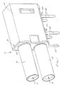
- FIG. 1 shows the front portions 14 of the tubular conductive shields which surround a pair of angled coaxial conductors, as will be described hereinafter.
- the front portions of the shields project outwardly of a one-piece overmolded plastic housing 16.
- a grounding clip, generally designated 18, includes a body portion 20 which embraces the two tubular shields, and a tail portion 22 for insertion into a hole in the printed circuit board and for electrical connection, as by soldering, to a ground circuit on the board and/or in the hole.
- a plurality of tail portions 24 of an additional pair of grounding clips project downwardly from overmolded housing 16, also for insertion into appropriate holes in the printed circuit board.
- Figure 2 shows the first fabrication step which is to overmold a one-piece, L-shaped dielectric sheath 26 about each of the pair of coaxial conductors of the module.
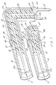
- Figure 7 shows the full extent of a pair of angled coaxial conductors, including an inside conductor generally designated 28 and an outside conductor generally designated 30, are shown in their full extent.
- Each conductor includes first and second legs 32 and 34, respectively, joined at a right-angular elbow 36.
- Legs 32 have distal ends 32a exposed outside sheaths 26.
- Legs 34 have distal ends 34a exposed outside sheaths 26.
- Distal ends 32a of legs 32 are disposed within front portions 14 of the tubular shields of the module for connection to the female contacts of an appropriate mating connecting device having portions inserted in the direction of arrows "A" (Fig. 7).
- Distal ends 34a of legs 34 are provided for attachment to appropriate circuit traces on the printed circuit board, as will be described hereinafter.
- each rear shield portion 38 of each tubular shield is axially split, as at 40, to define two L-shaped semi-tubular portions which are joined together to surround legs 34 and elbows 36 (Fig. 7) of angled coaxial conductors 30, as well as to surround substantial portions of legs 32 of the conductors, as seen by the L-shaped configurations of the rear shield portions shown in Figure 3.
- rear shield portions 38 have reduced-diameter portions 42 at the upper, forwardly facing ends thereof. The reduced-diameter portions form ring-like shoulders 44.
- FIG. 4 The next step is shown in Figure 4 wherein rear ends 46 of front shield portions 14 are inserted through holes 48 in body portion 20 of grounding clip 18.
- Each front shield portion 14 has a circular, outwardly projecting flange 50 against which the grounding clip abuts. It should be noted that front shield portions 14 are circumferentially continuous in cylindrical form, versus the axially split structure of rear shield portions 38.
- Figure 5 shows the subassembly of Figure 3 inserted into the rear of the subassembly of Figure 4.
- reduced-diameter portions 42 of rear shield portions 38 are inserted into rear portions 46 of front shield portions 14.
- the circumferentially continuous configuration of the front shield portions hold the axially split rear shield portions together.
- An alternative arrangement may include a pair of axially split, L-shaped shields which would enclose the dielectric sheaths 26 and be held together with the grounding clip 18 or the like.
- FIGs 6 and 7 show two additional grounding clips, generally designated 60, which include the tail portions 24 described above in relation to Figure 1.
- the tail portions project downwardly from a ring-like mounting portion 62 for each grounding clip 60.
- the ring-like mounting portion 62 of each grounding clip surrounds a reduced-diameter portion 64 of the respective rear shield portion 38.
- the mounting portion can be held onto the reduced-diameter portion by a press-fit, for instance.
- Grounding clip 18 (Figs. 4 and 5) has been removed from Figures 6 and 7 to facilitate the illustration. It should be understood that both grounding clip 18 and grounding clips 60 can be used as shown in Figure 8. By utilizing all of the grounding clips, a redundant grounding system is provided to ensure a good ground between the entire tubular shield of each coaxial conductor, including front shield portions 14 which are embraced by grounding clip 18 and rear shield portions 38 which are embraced by grounding clips 60.
- FIG 9 shows an alternate embodiment of grounding clips 60, and the grounding clips are generally designated 60A in Figure 9.
- the alternate embodiment of grounding clips 60A include only one tail portion 24.
- a pair of inverted U-shaped latches 66 project upwardly from opposite sides of each grounding clip. The latches snap onto ramped latch bosses 68 formed on opposite sides of rear shield portions 38.
- FIG 10 shows a further embodiment of grounding clips 60B which have inverted U-shaped body portions 70 which are snapped onto a pair of mounting bridges 72 formed integrally with rear shield portions 38 and projecting outwardly therefrom.
- Grounding clips 60B include a pair of the tail portions 24 for attachment to appropriate grounding circuit traces on the printed circuit board.
- Figures 9 and 10 show a process for easily attaching coaxial conductors 32 (Fig. 7) to appropriate circuit traces on the printed circuit board. Specifically, Figure 7 shows that distal ends 34a of legs 34 of coaxial conductors 28 and 30 are of reduced diameters. Figures 9 and 10 show a pair of preformed (cylindrical) solder plugs 74 which are press-fit over distal ends 34a of the coaxial conductors. These preformed solder plugs facilitate ready connection of the conductors to circuit traces on the printed circuit board by a surface-mount process.
- legs 34 of the angled coaxial conductors can extend further to comprise tail portions for insertion into appropriate holes in the printed circuit board and for connection, as by soldering, to circuit traces on the board and/or in the holes.
- Figure 11 shows the final step of overmolding dielectric housing 16 over the subassembly of Figure 8 (or Figs. 9 or 10) to form the completely fabricated coaxial connector module 12 initially described in relation to Figure 1.
- the housing is overmolded in an appropriate molding die, leaving the bottom of the housing open, as at 76, so that tail portions 24 of the grounding clips can project out of the housing, and preformed solder plugs 74 are exposed for soldering to the circuit traces on the printed circuit board.
- the bottom of the housing has portions 78 which define a mounting surface for positioning module 12 on the printed circuit board.
- the overmolding of the individual coaxial conductors to form the module 12 as described is not necessary. If desired the individual coaxial conductors may be held together by the grounding clip 18, or individually may be inserted into receptacles of a housing.
Landscapes
- Coupling Device And Connection With Printed Circuit (AREA)
- Details Of Connecting Devices For Male And Female Coupling (AREA)
- Manufacturing Of Electrical Connectors (AREA)
Abstract
Description
Claims (33)
- An angular coaxial connector module (12) for installation on a printed circuit board, comprising:at least a pair of angled coaxial conductors (28,30) each including first and second legs (32,34) joined at an elbow (36), a distal end (32a) of each first leg (32) defining a contact end of the respective conductor, and a distal end (34a) of each second leg (34) defining a terminal end for attachment to the printed circuit board;a dielectric sheath (26) about each angled coaxial conductor leaving the distal ends thereof exposed;a tubular conductive shield (14,38) about each dielectric sheath (26);grounding means (18,60) for coupling the shields (14,38) to the printed circuit board; anda unitary dielectric housing (16) about at least portions (38) of the shields (14,38) to hold the connector in a module.
- The coaxial connector module of claim 1 wherein said dielectric sheaths (26) are overmolded in tubular form about the angled coaxial conductors (28,30).
- The coaxial connector module of claim 1 wherein said tubular conductive shields (14,38) are generally cylindrical in cross-section.
- The coaxial connector module of claim 1 wherein each of said tubular conductive shields (14,38) includes a circumferentially continuous portion (14) about one leg (32) of the respective conductor leaving the respective distal end (32a) of the one leg exposed.
- The coaxial connector module of claim 1 wherein each of said tubular conductive shields (14,38) includes an axially split, L-shaped portion (38) about one leg (34) and the elbow (36) of the respective conductor leaving the distal end (34a) of the one leg exposed.
- The coaxial connector module of claim 5 wherein each of said tubular conductive shields (14,38) includes a circumferentially continuous portion (14) about the other leg (32) of the respective conductor leaving the distal end (32a) of the other leg exposed.
- The coaxial connector module of claim 6 wherein said circumferentially continuous portion (14) of each shield includes an end (46) surrounding an adjacent end (42) of the axially split portion (38) of the shield to hold the axially split portion together.
- The coaxial connector module of claim 1 wherein said grounding means comprises at least one grounding clip (18,60) having at least one tail portion (22,24) for attachment to the printed circuit board.
- The coaxial connector module of claim 8 wherein said grounding clip (18) includes a body portion (20) embracing the conductive shields (14) of both coaxial conductors (28,30).
- The coaxial connector module of claim 8, including one of said grounding clips (18) embracing each conductive shield.(14).
- The coaxial connector module of claim 1 wherein said housing (16) comprises a one-piece plastic structure overmolded about at least portions of the shields (14,38).
- The coaxial connector of claim 3 wherein each of said tubular shield is axially split.
- An angular coaxial connector module (12) for installation on a printed circuit board, comprising:at least a pair of angled coaxial conductors (28,30) each including first and second legs (32,34) joined at an elbow (36), the distal end (32a) of each first leg (32) defining a contact end of the respective conductor, and a distal end (34a) of each second leg (34) defining a terminal end for attachment to a printed circuit board;a dielectric sheath (26) overmolded in tubular form about each angled coaxial conductor (28,30) leading the distal ends (32a,34a) thereof exposed;a tubular conductive shield (14,38) about each dielectric sheath (26), each shield including an axially split, L-shaped portion (38) about one leg (34) and the elbow (36) of the respective conductor leaving the distal end (34a) of the one leg exposed, a circumferentially continuous portion (14) about the other leg (32) leaving the distal end (32a) of the other leg exposed, and the circumferentially continuous portion (14) having an end (42) surrounding an adjacent end (42) of the axially split portion to hold the axially split portion together;at least one grounding clip (18,60) having at least one tail portion (22,24) for attachment to the printed circuit board; anda one-piece plastic housing (16) overmolded about at least portions (38) of the shields (14,38) to hold the connector in a module.
- The coaxial connector module of claim 13 wherein said shield portions (14,38) of the tubular conductive shield are generally cylindrical in cross-section.
- The coaxial connector module of claim 13, including one of said grounding clips (18) embracing each conductive shield (14).
- The coaxial connector module of claim 13 wherein said grounding clip (18) includes a body portion (20) embracing the conductive shields (14) of both coaxial conductors (28,30).
- An angular coaxial connector module (12) for installation on a printed circuit board, comprising:at least a pair of angled coaxial conductors (28,30) each including first and second legs (32,34) joined at an elbow (36), a distal end (32a) of each first leg (32) defining a contact end of the respective conductor, and a distal end (34a) of each second leg (34) defining a terminal end for attachment to the printed circuit board;a dielectric sheath (26) about each angled coaxial conductor leaving the distal end thereof exposed;a conductive shield (14,38) about each dielectric sheath (26); anda unitary dielectric housing (16) about at least portions (38) of the shields (14,38) to hold the connector in a module.
- The coaxial connector module of claim 17 wherein said dielectric sheaths (26) are overmolded in tubular form about the angled coaxial conductors (28,30).
- The coaxial connector module of claim 17 wherein each of said tubular conductive shields (14,38) includes an axially split, L-shaped portion (38) about one leg (34) and the elbow (36) of the respective conductor leaving the distal end (34a) of the one leg exposed, a circumferentially continuous portion (14) about the other leg (32) of the respective conductor leaving the distal end (32a) of the other leg exposed, said circumferentially continuous portion (14) of each shield including an end (46) surrounding an adjacent end (42) of the axially split portion (38) of the shield to hold the axially split portion together.
- The coaxial connector module of claim 17 wherein said grounding means comprises at least one grounding clip (18,60) having at least one tail portion (22,24) for attachment to the printed circuit board.
- The coaxial connector module of claim 20 wherein said grounding clip (18) includes a body portion (20) embracing the conductive shields (14) of both coaxial conductors (28,30).
- The coaxial connector module of claim 21, including one of said grounding clips (18) embracing each conductive shield (14).
- The coaxial connector module of claim 17 wherein said housing (16) comprises a one-piece plastic structure overmolded about at least portions of the shields (14,38).
- A method of fabricating an angular coaxial connector module (12) for installation on a printed circuit board, comprising:providing at least a pair of angled coaxial conductors (28,30) each including first and second legs (32,34) joined at an elbow (36), a distal end (32a) of each first leg (32) defining a contact end of the respective conductor, and a distal end (34a) of each second leg (34) defining a terminal end for attachment to the printed circuit board;positioning a dielectric sheath (26) about each angled coaxial conductor leaving the distal ends thereof exposed;positioning a tubular conductive shield (14,38) about each dielectric sheath (26);positioning a grounding means (18,60) on the shields for connection to the printed circuit board; andproviding a unitary dielectric housing (16) about at least portions (38) of the shields (14,38) to hold the connector in a module.
- The method of claim 24 including overmolding said dielectric sheaths (26) in tubular form about the angled coaxial conductors (28,30).
- The method of claim 24 including overmolding said housing (16) in a one-piece plastic structure about at least portions (38) of the shields(14,38).
- The method of claim 26 including providing each of said conductive shields (14,38) with an axially split, L-shaped portion (38) about one leg (34) and the elbow (36) of the respective conductor leaving the distal end (34a) of the one leg exposed, with a circumferentially continuous portion (14) about the other leg (32) of the respective conductor leaving the distal end (32a) of the other leg exposed, and with an end (46) of the circumferentially continuous portion (14) surrounding an adjacent end (42) of the axially split portion (38) to hold the axially split portion together.
- A method of fabricating an angular coaxial connector module (12) for installation on a printed circuit board, comprising:providing at least a pair of angled coaxial conductors (28,30) each including first and second legs (32,34) joined at an elbow (36), a distal end (32a) of each first leg (32) defining a contact end of the respective conductor, and a distal end (34a) of each second leg (34) defining a terminal end for attachment to the printed circuit board;positioning a dielectric sheath (26) about each angled coaxial conductor leaving the distal ends thereof exposed;positioning a tubular conductive shield (14,38) about each dielectric sheath (26); andpositioning a grounding means (18,60) on the shields for connection to the printed circuit board.
- The method of claim 28 including overmolding said dielectric sheaths (26) in tubular form about the angled coaxial conductors (28,30).
- An angular coaxial connector module (12) for installation on a printed círcuit board, comprising:at least a pair of angled coaxial conductors (28,30) each including first and second legs (32,34) joined at an elbow (36), a distal end (32a) of each first leg (32) defining a contact end of the respective conductor, and a distal end (34a) of each second leg (34) defining a terminal end for attachment to the printed circuit board;a dielectric sheath (26) about each angled coaxial conductor leaving the distal ends thereof exposed;a tubular conductive shield (14,38) about each dielectric sheath (26); anda grounding means (18,60) for coupling the shields (14,38) to the printed circuit board.
- The coaxial connector module of claim 30 wherein said dielectric sheaths (26) are overmolded in tubular form about the angled coaxial conductors (28,30).
- The coaxial connector module of claim 30 wherein said tubular conductive shields (14,38) are generally cylindrical in cross-section.
- The coaxial connector module of claim 30 wherein each of said tubular conductive shields (14, 38) is axially split.
Applications Claiming Priority (2)
| Application Number | Priority Date | Filing Date | Title |
|---|---|---|---|
| US651634 | 2000-08-30 | ||
| US09/651,634 US6575761B1 (en) | 2000-08-30 | 2000-08-30 | Coaxial connector module and method of fabricating same |
Publications (3)
| Publication Number | Publication Date |
|---|---|
| EP1187268A2 true EP1187268A2 (en) | 2002-03-13 |
| EP1187268A3 EP1187268A3 (en) | 2002-09-25 |
| EP1187268B1 EP1187268B1 (en) | 2006-03-22 |
Family
ID=24613608
Family Applications (1)
| Application Number | Title | Priority Date | Filing Date |
|---|---|---|---|
| EP01120502A Expired - Lifetime EP1187268B1 (en) | 2000-08-30 | 2001-08-28 | Coaxial connector module and method of fabricating same |
Country Status (5)
| Country | Link |
|---|---|
| US (1) | US6575761B1 (en) |
| EP (1) | EP1187268B1 (en) |
| JP (2) | JP2002270311A (en) |
| CN (1) | CN1245786C (en) |
| DE (1) | DE60118069T2 (en) |
Cited By (4)
| Publication number | Priority date | Publication date | Assignee | Title |
|---|---|---|---|---|
| EP1653575A1 (en) * | 2004-10-27 | 2006-05-03 | Osram Sylvania Inc. | Method of making an electrical connector |
| WO2015010776A1 (en) * | 2013-07-24 | 2015-01-29 | Rosenberger Hochfrequenztechnik Gmbh & Co. Kg | System consisting of a printed circuit board and tubular casing |
| GB2493589B (en) * | 2011-05-31 | 2017-05-31 | Adder Tech Ltd | Electronic device security |
| EP3324492B1 (en) * | 2015-03-03 | 2023-08-09 | Fujitsu Component Limited | Connector |
Families Citing this family (33)
| Publication number | Priority date | Publication date | Assignee | Title |
|---|---|---|---|---|
| JP2904132B2 (en) | 1996-06-14 | 1999-06-14 | 日本電気株式会社 | Jig for measuring high frequency semiconductor devices |
| USD491534S1 (en) | 2003-05-06 | 2004-06-15 | Hon Hai Precision Ind. Co., Ltd. | Cable end connector assembly |
| US6908346B1 (en) * | 2004-01-20 | 2005-06-21 | Itt Manufacturing Enterprises, Inc. | Quad cable interface using available insert |
| US7137825B2 (en) * | 2004-03-31 | 2006-11-21 | Tyco Electronics Corporation | Shielded electrical jack connector |
| US7264499B2 (en) * | 2004-10-14 | 2007-09-04 | Pent Technologies, Inc. | Power entry assembly for an electrical distribution system |
| USD527345S1 (en) * | 2004-12-15 | 2006-08-29 | Hon Hai Precision Ind. Co., Ltd. | Power connector |
| US7121883B1 (en) * | 2005-06-06 | 2006-10-17 | John Mezzalingua Associates, Inc. | Coax connector having steering insulator |
| CN100550536C (en) * | 2005-06-09 | 2009-10-14 | 株式会社自动网络技术研究所 | Mounting structure of coaxial connector and connector housing of coaxial connector |
| US7150648B1 (en) * | 2005-11-02 | 2006-12-19 | Tyco Electronics Corporation | Surface mount electrical connector |
| TWI323062B (en) * | 2006-11-08 | 2010-04-01 | Unihan Corp | Connector with torque limiting control and coaxial connector assembly thereof |
| US7473137B2 (en) * | 2007-03-30 | 2009-01-06 | Intel Corporation | Right-angle coaxial connector |
| US8259457B2 (en) * | 2007-08-16 | 2012-09-04 | Arris Group, Inc. | Formed shielding feature |
| USD612811S1 (en) | 2008-09-12 | 2010-03-30 | Tyco Electronics Corporation | Contact isolator |
| US8011950B2 (en) * | 2009-02-18 | 2011-09-06 | Cinch Connectors, Inc. | Electrical connector |
| JP5489691B2 (en) * | 2009-12-16 | 2014-05-14 | 矢崎総業株式会社 | Insulation structure of L-shaped terminal |
| US8888519B2 (en) | 2012-05-31 | 2014-11-18 | Cinch Connectivity Solutions, Inc. | Modular RF connector system |
| US9093800B2 (en) * | 2012-10-23 | 2015-07-28 | Tyco Electronics Corporation | Leadframe module for an electrical connector |
| DE102013200810A1 (en) * | 2013-01-18 | 2014-07-24 | Robert Bosch Gmbh | Shielding arrangement for an electrical connector |
| JP5737533B2 (en) * | 2013-06-12 | 2015-06-17 | Smk株式会社 | Multi-pole connector |
| CN106816786B (en) * | 2015-11-27 | 2021-02-26 | 富士康(昆山)电脑接插件有限公司 | Radio frequency connector assembly |
| JP1568066S (en) * | 2016-04-22 | 2017-01-30 | ||
| EP3507869B1 (en) * | 2016-09-19 | 2021-07-28 | Huawei Technologies Co., Ltd. | Shielded board-to-board connector |
| JP2018063892A (en) * | 2016-10-14 | 2018-04-19 | 日本圧着端子製造株式会社 | Coaxial connector |
| JP6853998B2 (en) * | 2016-10-14 | 2021-04-07 | 日本圧着端子製造株式会社 | Coaxial connector mounting structure |
| US11205867B2 (en) | 2017-09-15 | 2021-12-21 | Molex, Llc | Grid array connector system |
| KR102397282B1 (en) * | 2017-09-15 | 2022-05-13 | 몰렉스 엘엘씨 | Grid Array Connector System |
| JP6489342B1 (en) * | 2018-07-26 | 2019-03-27 | Smk株式会社 | connector |
| JP2019021649A (en) * | 2018-11-12 | 2019-02-07 | 富士通コンポーネント株式会社 | connector |
| DE102019101491A1 (en) * | 2019-01-22 | 2020-07-23 | Engeser Gmbh Innovative Verbindungstechnik | Protective sleeve to protect shielded cables |
| JP6879647B2 (en) * | 2019-02-27 | 2021-06-02 | 住友電装株式会社 | Shield terminal and shield connector |
| JP7363440B2 (en) | 2019-12-10 | 2023-10-18 | 株式会社オートネットワーク技術研究所 | connector |
| JP2021111439A (en) * | 2020-01-06 | 2021-08-02 | 矢崎総業株式会社 | Shielded connector for board |
| US11146026B1 (en) * | 2020-07-06 | 2021-10-12 | Dongguan Way Way Electronic Technology Co., Ltd | Electrical connector having shielding function |
Family Cites Families (9)
| Publication number | Priority date | Publication date | Assignee | Title |
|---|---|---|---|---|
| GB9019540D0 (en) | 1990-09-07 | 1990-10-24 | Amp Great Britain | Coaxial electrical connectors and their manufacture |
| US5169343A (en) | 1990-11-29 | 1992-12-08 | E. I. Du Pont De Nemours And Company | Coax connector module |
| FR2685553A1 (en) | 1991-12-18 | 1993-06-25 | Radiall Sa | COAXIAL CONNECTOR ELEMENT ELBOW FIXED TO A PRINTED BOARD. |
| FR2702095B1 (en) | 1993-02-26 | 1995-04-14 | Radiall Sa | Angled coaxial connector element capable of being fixed to a printed circuit board. |
| FR2726128B1 (en) | 1994-10-19 | 1996-12-27 | Radiall Sa | MULTI-WAY ELECTRICAL CONNECTOR WITHOUT ELECTROMAGNETIC BARRIER BETWEEN TRACKS |
| DE4438872C1 (en) | 1994-11-03 | 1995-12-07 | Harting Elektronik Gmbh | Coaxial angle connector for PCB |
| FR2746971B1 (en) * | 1996-04-01 | 1998-04-30 | Framatome Connectors France | MINIATURE SHIELDED CONNECTOR WITH BENDED CONTACT RODS |
| DE19707490C2 (en) | 1997-02-25 | 2000-05-11 | Siemens Ag | RF coaxial connector |
| US6305947B1 (en) * | 1998-11-19 | 2001-10-23 | Berg Technology, Inc. | Angled coaxial connector module |
-
2000
- 2000-08-30 US US09/651,634 patent/US6575761B1/en not_active Expired - Fee Related
-
2001
- 2001-08-28 DE DE60118069T patent/DE60118069T2/en not_active Expired - Fee Related
- 2001-08-28 EP EP01120502A patent/EP1187268B1/en not_active Expired - Lifetime
- 2001-08-29 CN CN01130335.2A patent/CN1245786C/en not_active Expired - Fee Related
- 2001-08-30 JP JP2001309241A patent/JP2002270311A/en active Pending
-
2005
- 2005-06-24 JP JP2005004822U patent/JP3114071U/en not_active Expired - Fee Related
Cited By (5)
| Publication number | Priority date | Publication date | Assignee | Title |
|---|---|---|---|---|
| EP1653575A1 (en) * | 2004-10-27 | 2006-05-03 | Osram Sylvania Inc. | Method of making an electrical connector |
| US7114247B2 (en) | 2004-10-27 | 2006-10-03 | Osram Sylvania Inc. | Method of making an electrical connector |
| GB2493589B (en) * | 2011-05-31 | 2017-05-31 | Adder Tech Ltd | Electronic device security |
| WO2015010776A1 (en) * | 2013-07-24 | 2015-01-29 | Rosenberger Hochfrequenztechnik Gmbh & Co. Kg | System consisting of a printed circuit board and tubular casing |
| EP3324492B1 (en) * | 2015-03-03 | 2023-08-09 | Fujitsu Component Limited | Connector |
Also Published As
| Publication number | Publication date |
|---|---|
| DE60118069D1 (en) | 2006-05-11 |
| JP3114071U (en) | 2005-09-29 |
| EP1187268B1 (en) | 2006-03-22 |
| CN1245786C (en) | 2006-03-15 |
| JP2002270311A (en) | 2002-09-20 |
| EP1187268A3 (en) | 2002-09-25 |
| DE60118069T2 (en) | 2006-11-02 |
| CN1349288A (en) | 2002-05-15 |
| US6575761B1 (en) | 2003-06-10 |
Similar Documents
| Publication | Publication Date | Title |
|---|---|---|
| US6575761B1 (en) | Coaxial connector module and method of fabricating same | |
| US4634208A (en) | Electrical plug connector and method of terminating a cable therewith | |
| EP1766728B1 (en) | Modular plug assemblies, terminated cable assemblies and methods for forming the same | |
| CA1178351A (en) | Coaxial connector assembly | |
| EP0118168B2 (en) | Electrical plug connector and receptacle therefor | |
| US4838811A (en) | Modular connector with EMI countermeasure | |
| US5865646A (en) | Connector shield with integral latching and ground structure | |
| EP0590544B1 (en) | Shielded electrical connector assembly | |
| US7040917B2 (en) | Electrical connector assembly | |
| EP0624928B1 (en) | Shielded electrical connector assembly | |
| JP2003163058A (en) | Shield connector | |
| US20040259421A1 (en) | Cable connector assembly having improved shield members | |
| GB2257851A (en) | Shielded connector. | |
| JPH0652936A (en) | Electric connector | |
| US5611711A (en) | Electrical connector assembly | |
| EP1003248A3 (en) | Angled coaxial connector module | |
| US6821150B2 (en) | Connector assembly having dielectric cover | |
| WO1986005035A1 (en) | Coaxial cable terminator | |
| JP3738388B2 (en) | Coaxial connector | |
| US6234840B1 (en) | Shield connector | |
| US5975955A (en) | Shielded electrical connector assembly with grounding system | |
| US6106334A (en) | Shielded cable connector | |
| CA2157087C (en) | Plug-type connector for wiring backplanes | |
| EP0510264B1 (en) | Coaxial cable connector system | |
| US20030034165A1 (en) | Method and apparatus for external grounding of plastic backshell connectors |
Legal Events
| Date | Code | Title | Description |
|---|---|---|---|
| PUAI | Public reference made under article 153(3) epc to a published international application that has entered the european phase |
Free format text: ORIGINAL CODE: 0009012 |
|
| AK | Designated contracting states |
Kind code of ref document: A2 Designated state(s): AT BE CH CY DE DK ES FI FR GB GR IE IT LI LU MC NL PT SE TR |
|
| AX | Request for extension of the european patent |
Free format text: AL;LT;LV;MK;RO;SI |
|
| PUAL | Search report despatched |
Free format text: ORIGINAL CODE: 0009013 |
|
| AK | Designated contracting states |
Kind code of ref document: A3 Designated state(s): AT BE CH CY DE DK ES FI FR GB GR IE IT LI LU MC NL PT SE TR |
|
| AX | Request for extension of the european patent |
Free format text: AL;LT;LV;MK;RO;SI |
|
| 17P | Request for examination filed |
Effective date: 20030315 |
|
| AKX | Designation fees paid |
Designated state(s): DE FI FR GB SE |
|
| 17Q | First examination report despatched |
Effective date: 20030515 |
|
| GRAP | Despatch of communication of intention to grant a patent |
Free format text: ORIGINAL CODE: EPIDOSNIGR1 |
|
| GRAS | Grant fee paid |
Free format text: ORIGINAL CODE: EPIDOSNIGR3 |
|
| GRAA | (expected) grant |
Free format text: ORIGINAL CODE: 0009210 |
|
| AK | Designated contracting states |
Kind code of ref document: B1 Designated state(s): DE FI FR GB SE |
|
| REG | Reference to a national code |
Ref country code: GB Ref legal event code: FG4D |
|
| REG | Reference to a national code |
Ref country code: SE Ref legal event code: TRGR |
|
| REF | Corresponds to: |
Ref document number: 60118069 Country of ref document: DE Date of ref document: 20060511 Kind code of ref document: P |
|
| ET | Fr: translation filed | ||
| PLBE | No opposition filed within time limit |
Free format text: ORIGINAL CODE: 0009261 |
|
| STAA | Information on the status of an ep patent application or granted ep patent |
Free format text: STATUS: NO OPPOSITION FILED WITHIN TIME LIMIT |
|
| 26N | No opposition filed |
Effective date: 20061227 |
|
| PGFP | Annual fee paid to national office [announced via postgrant information from national office to epo] |
Ref country code: FI Payment date: 20080828 Year of fee payment: 8 Ref country code: FR Payment date: 20080818 Year of fee payment: 8 |
|
| PGFP | Annual fee paid to national office [announced via postgrant information from national office to epo] |
Ref country code: GB Payment date: 20080827 Year of fee payment: 8 |
|
| PGFP | Annual fee paid to national office [announced via postgrant information from national office to epo] |
Ref country code: DE Payment date: 20080930 Year of fee payment: 8 |
|
| PGFP | Annual fee paid to national office [announced via postgrant information from national office to epo] |
Ref country code: SE Payment date: 20080827 Year of fee payment: 8 |
|
| GBPC | Gb: european patent ceased through non-payment of renewal fee |
Effective date: 20090828 |
|
| PG25 | Lapsed in a contracting state [announced via postgrant information from national office to epo] |
Ref country code: FI Free format text: LAPSE BECAUSE OF NON-PAYMENT OF DUE FEES Effective date: 20090828 |
|
| REG | Reference to a national code |
Ref country code: FR Ref legal event code: ST Effective date: 20100430 |
|
| PG25 | Lapsed in a contracting state [announced via postgrant information from national office to epo] |
Ref country code: DE Free format text: LAPSE BECAUSE OF NON-PAYMENT OF DUE FEES Effective date: 20100302 Ref country code: FR Free format text: LAPSE BECAUSE OF NON-PAYMENT OF DUE FEES Effective date: 20090831 |
|
| PG25 | Lapsed in a contracting state [announced via postgrant information from national office to epo] |
Ref country code: GB Free format text: LAPSE BECAUSE OF NON-PAYMENT OF DUE FEES Effective date: 20090828 |
|
| PG25 | Lapsed in a contracting state [announced via postgrant information from national office to epo] |
Ref country code: SE Free format text: LAPSE BECAUSE OF NON-PAYMENT OF DUE FEES Effective date: 20090829 |