EP1188482A2 - Apparatus & method for conducting assays - Google Patents
Apparatus & method for conducting assays Download PDFInfo
- Publication number
- EP1188482A2 EP1188482A2 EP01123697A EP01123697A EP1188482A2 EP 1188482 A2 EP1188482 A2 EP 1188482A2 EP 01123697 A EP01123697 A EP 01123697A EP 01123697 A EP01123697 A EP 01123697A EP 1188482 A2 EP1188482 A2 EP 1188482A2
- Authority
- EP
- European Patent Office
- Prior art keywords
- disc
- space
- opening
- fluid
- wells
- Prior art date
- Legal status (The legal status is an assumption and is not a legal conclusion. Google has not performed a legal analysis and makes no representation as to the accuracy of the status listed.)
- Withdrawn
Links
Images

Classifications
-
- B—PERFORMING OPERATIONS; TRANSPORTING
- B01—PHYSICAL OR CHEMICAL PROCESSES OR APPARATUS IN GENERAL
- B01L—CHEMICAL OR PHYSICAL LABORATORY APPARATUS FOR GENERAL USE
- B01L3/00—Containers or dishes for laboratory use, e.g. laboratory glassware; Droppers
- B01L3/50—Containers for the purpose of retaining a material to be analysed, e.g. test tubes
- B01L3/508—Rigid containers without fluid transport within
- B01L3/5085—Rigid containers without fluid transport within for multiple samples, e.g. microtitration plates
- B01L3/50855—Rigid containers without fluid transport within for multiple samples, e.g. microtitration plates using modular assemblies of strips or of individual wells
-
- B—PERFORMING OPERATIONS; TRANSPORTING
- B01—PHYSICAL OR CHEMICAL PROCESSES OR APPARATUS IN GENERAL
- B01L—CHEMICAL OR PHYSICAL LABORATORY APPARATUS FOR GENERAL USE
- B01L3/00—Containers or dishes for laboratory use, e.g. laboratory glassware; Droppers
- B01L3/50—Containers for the purpose of retaining a material to be analysed, e.g. test tubes
- B01L3/508—Rigid containers without fluid transport within
- B01L3/5085—Rigid containers without fluid transport within for multiple samples, e.g. microtitration plates
-
- G—PHYSICS
- G01—MEASURING; TESTING
- G01N—INVESTIGATING OR ANALYSING MATERIALS BY DETERMINING THEIR CHEMICAL OR PHYSICAL PROPERTIES
- G01N33/00—Investigating or analysing materials by specific methods not covered by groups G01N1/00 - G01N31/00
- G01N33/48—Biological material, e.g. blood, urine; Haemocytometers
- G01N33/50—Chemical analysis of biological material, e.g. blood, urine; Testing involving biospecific ligand binding methods; Immunological testing
- G01N33/53—Immunoassay; Biospecific binding assay; Materials therefor
- G01N33/5302—Apparatus specially adapted for immunological test procedures
- G01N33/5304—Reaction vessels, e.g. agglutination plates
-
- B—PERFORMING OPERATIONS; TRANSPORTING
- B01—PHYSICAL OR CHEMICAL PROCESSES OR APPARATUS IN GENERAL
- B01L—CHEMICAL OR PHYSICAL LABORATORY APPARATUS FOR GENERAL USE
- B01L2200/00—Solutions for specific problems relating to chemical or physical laboratory apparatus
- B01L2200/02—Adapting objects or devices to another
- B01L2200/025—Align devices or objects to ensure defined positions relative to each other
-
- B—PERFORMING OPERATIONS; TRANSPORTING
- B01—PHYSICAL OR CHEMICAL PROCESSES OR APPARATUS IN GENERAL
- B01L—CHEMICAL OR PHYSICAL LABORATORY APPARATUS FOR GENERAL USE
- B01L2200/00—Solutions for specific problems relating to chemical or physical laboratory apparatus
- B01L2200/06—Fluid handling related problems
- B01L2200/0642—Filling fluids into wells by specific techniques
-
- B—PERFORMING OPERATIONS; TRANSPORTING
- B01—PHYSICAL OR CHEMICAL PROCESSES OR APPARATUS IN GENERAL
- B01L—CHEMICAL OR PHYSICAL LABORATORY APPARATUS FOR GENERAL USE
- B01L2300/00—Additional constructional details
- B01L2300/02—Identification, exchange or storage of information
- B01L2300/021—Identification, e.g. bar codes
-
- B—PERFORMING OPERATIONS; TRANSPORTING
- B01—PHYSICAL OR CHEMICAL PROCESSES OR APPARATUS IN GENERAL
- B01L—CHEMICAL OR PHYSICAL LABORATORY APPARATUS FOR GENERAL USE
- B01L2300/00—Additional constructional details
- B01L2300/08—Geometry, shape and general structure
- B01L2300/0803—Disc shape
-
- B—PERFORMING OPERATIONS; TRANSPORTING
- B01—PHYSICAL OR CHEMICAL PROCESSES OR APPARATUS IN GENERAL
- B01L—CHEMICAL OR PHYSICAL LABORATORY APPARATUS FOR GENERAL USE
- B01L2300/00—Additional constructional details
- B01L2300/16—Surface properties and coatings
- B01L2300/161—Control and use of surface tension forces, e.g. hydrophobic, hydrophilic
- B01L2300/165—Specific details about hydrophobic, oleophobic surfaces
-
- B—PERFORMING OPERATIONS; TRANSPORTING
- B01—PHYSICAL OR CHEMICAL PROCESSES OR APPARATUS IN GENERAL
- B01L—CHEMICAL OR PHYSICAL LABORATORY APPARATUS FOR GENERAL USE
- B01L2400/00—Moving or stopping fluids
- B01L2400/04—Moving fluids with specific forces or mechanical means
- B01L2400/0403—Moving fluids with specific forces or mechanical means specific forces
- B01L2400/0406—Moving fluids with specific forces or mechanical means specific forces capillary forces
-
- B—PERFORMING OPERATIONS; TRANSPORTING
- B01—PHYSICAL OR CHEMICAL PROCESSES OR APPARATUS IN GENERAL
- B01L—CHEMICAL OR PHYSICAL LABORATORY APPARATUS FOR GENERAL USE
- B01L3/00—Containers or dishes for laboratory use, e.g. laboratory glassware; Droppers
- B01L3/50—Containers for the purpose of retaining a material to be analysed, e.g. test tubes
- B01L3/502—Containers for the purpose of retaining a material to be analysed, e.g. test tubes with fluid transport, e.g. in multi-compartment structures
- B01L3/5027—Containers for the purpose of retaining a material to be analysed, e.g. test tubes with fluid transport, e.g. in multi-compartment structures by integrated microfluidic structures, i.e. dimensions of channels and chambers are such that surface tension forces are important, e.g. lab-on-a-chip
-
- B—PERFORMING OPERATIONS; TRANSPORTING
- B01—PHYSICAL OR CHEMICAL PROCESSES OR APPARATUS IN GENERAL
- B01L—CHEMICAL OR PHYSICAL LABORATORY APPARATUS FOR GENERAL USE
- B01L3/00—Containers or dishes for laboratory use, e.g. laboratory glassware; Droppers
- B01L3/50—Containers for the purpose of retaining a material to be analysed, e.g. test tubes
- B01L3/508—Rigid containers without fluid transport within
- B01L3/5088—Rigid containers without fluid transport within confining liquids at a location by surface tension, e.g. virtual wells on plates, wires
-
- G—PHYSICS
- G01—MEASURING; TESTING
- G01N—INVESTIGATING OR ANALYSING MATERIALS BY DETERMINING THEIR CHEMICAL OR PHYSICAL PROPERTIES
- G01N35/00—Automatic analysis not limited to methods or materials provided for in any single one of groups G01N1/00 - G01N33/00; Handling materials therefor
- G01N35/02—Automatic analysis not limited to methods or materials provided for in any single one of groups G01N1/00 - G01N33/00; Handling materials therefor using a plurality of sample containers moved by a conveyor system past one or more treatment or analysis stations
- G01N35/04—Details of the conveyor system
- G01N2035/0439—Rotary sample carriers, i.e. carousels
- G01N2035/0451—Rotary sample carriers, i.e. carousels composed of interchangeable sectors
-
- Y—GENERAL TAGGING OF NEW TECHNOLOGICAL DEVELOPMENTS; GENERAL TAGGING OF CROSS-SECTIONAL TECHNOLOGIES SPANNING OVER SEVERAL SECTIONS OF THE IPC; TECHNICAL SUBJECTS COVERED BY FORMER USPC CROSS-REFERENCE ART COLLECTIONS [XRACs] AND DIGESTS
- Y10—TECHNICAL SUBJECTS COVERED BY FORMER USPC
- Y10T—TECHNICAL SUBJECTS COVERED BY FORMER US CLASSIFICATION
- Y10T436/00—Chemistry: analytical and immunological testing
- Y10T436/11—Automated chemical analysis
- Y10T436/111666—Utilizing a centrifuge or compartmented rotor
-
- Y—GENERAL TAGGING OF NEW TECHNOLOGICAL DEVELOPMENTS; GENERAL TAGGING OF CROSS-SECTIONAL TECHNOLOGIES SPANNING OVER SEVERAL SECTIONS OF THE IPC; TECHNICAL SUBJECTS COVERED BY FORMER USPC CROSS-REFERENCE ART COLLECTIONS [XRACs] AND DIGESTS
- Y10—TECHNICAL SUBJECTS COVERED BY FORMER USPC
- Y10T—TECHNICAL SUBJECTS COVERED BY FORMER US CLASSIFICATION
- Y10T436/00—Chemistry: analytical and immunological testing
- Y10T436/25—Chemistry: analytical and immunological testing including sample preparation
- Y10T436/2575—Volumetric liquid transfer
Definitions
- the present invention relates to apparatus and to a method for conducting assays and, in particular, to multi-well plate structures for receiving and holding, in separate wells, volumes of liquid for the purpose of conducting chemical or biochemical assays.
- Multi-well trays or plates having a 2-dimensional array of small wells are commonly used in medicine and science to facilitate testing of a liquid analyte.
- One particular area of use is blood screening where blood or blood products are introduced into the wells to test for viruses such as HIV, hepatitis etc.
- Such tests typically involve an antigen-antibody interaction, where the surfaces of the wells are coated with specific antigen itself. This approach detects circulating antibodies to that specific antigen.
- the wells can be coated with a specific antibody which captures circulating antigen which is, in turn, identified by a second antibody directed against a second epitope on the captured antigen.
- the wells of a tray be contained within a substantially closed container, e.g. to avoid the risk of contamination of the wells and of leakage of contaminated material.
- trays such as this, it may be difficult or impossible to gain access to the wells to enable them to be filled using a micro-pipette.
- a multi-well assay plate structure which defines a relatively shallow substantially enclosed space above a plurality of wells, with the enclosed space having an inlet and an outlet separate from the inlet. Fluid introduced via the inlet flows into the space, and covers the wells, by displacing air. Withdrawal of the fluid from the space via the inlet or outlet leaves fluid in the wells allowing various tests to be performed.
- a multi-well assay plate structure comprising:
- the chamber is shallow enough to allow fluid to fill the wells and the chamber.
- the wells are deep enough to retain a volume of fluid following withdrawal of fluid in the space above the wells.
- the plate structure can be of any convenient shape but, advantageously, is sector-shaped with a detachable handle at the longer arc-portion to facilitate locating the sector on a disc. Conveniently, a plurality of sector-shaped structures are located on the disc.
- the sectors and discs are made of plastic and the sectors can be snap-fitted onto the disc.
- the sectors and the disc include lock and key portions to allow the sectors to be snap-fitted in the correct orientation only.
- a disc with a plurality of separate sections can be manufactured or moulded in one piece instead of snap-in sectors.
- the composite structure may be snap-fitted onto a compact disk.
- the disk structure may have a circumferential gutter extending around its periphery to facilitate collection of fluid following fluid introduction/withdrawal from the chamber.
- the wells are dimensioned and proportioned in terms of diameter and depth to receive and retain fluid containing the analyte or part of the reagent under test.
- the exact dimensions are a matter of choice and depend on a number of parameters such as the type of material of the surfaces of the chamber and wells; viscosity of the fluid and the depth (height) of the space between the first and second surfaces.
- the dimensions of the structure are such that the wells fill to retain sufficient fluid the space is flooded and withdrawal to allow a measurable reaction to be measured within an individual well without contribution from adjacent wells.
- the overall process of sequential steps of flood and fill is advantageous in that it allows both discrete measurements within individual wells when filled and efficient washing of an array of wells (flood) which is useful in multistep procedures, such as immunoassays, which requires sequential application of reagents interspersed with rigorous washing steps. This permits the wells to be cleaned or rinsed in the same way as filling to allow subsequent tests to be carried out within an individual well whilst avoiding cross-contamination between adjacent wells.
- the structure is preferably made of transparent or otherwise optically transmissive plastic to facilitate optical reading of the wells to determine the results of the tests.
- the structure is integrated with automatic fluid handling apparatus and an optical reader to allow automatic fluid handling and optical assessment of the results of the reactions.
- fluid handling can be manually controlled and the results of the reactions within the structure can be assessed by an optical reader or be scored by visual assessment.
- a multi-well assay structure comprising an upper surface and a lower closely spaced opposed surface, said upper and lower surfaces defining a relatively shallow space therebetween, the lower surface having a plurality of wells therein, at least two spaced apart openings providing access to said space from an external location, wherein a fluid introduced into said space through one of said openings fills substantially all of the space and covers of the wells and said fluid, when subsequently withdrawn through the same or the other opening, leaves the wells filled with liquid.
- the volume of fluid introduced into each well when using the structure of the present invention is substantially defined by the volume of the well.
- the accuracy and precision with which the wells can be filled is therefore defined by the accuracy and precision with which the wells can be fabricated and which is generally high.
- the multiplicity of wells can be filled by way of a single injection and withdrawal of fluid through an opening into the space containing the wells, so that the wells can be filled extremely rapidly.
- the structure of the present invention provides for the filling of a plurality of wells in a substantially closed chamber, the only openings into that container being the fluid injection opening and a second 'vent' opening.
- the structure of the present invention simplifies the process of cleaning or rinsing previously filled wells as this can be achieved by repeatedly injecting and withdrawing fluid through one of said openings.
- the spacing between said upper and lower surfaces is sufficiently small to facilitate the flow of fluid in said space by capillary or capillary like action.
- the spacing is less than 1mm and preferably less than 0.5mm.
- said upper and lower surfaces are substantially planer.
- the wells may have any suitable geometry.
- the wells may be provided in said lower surface by blind circular holes with a semi-spherical termination.
- the wells may have substantially straight sidewalls, e.g. so that the sidewalls extend substantially vertically and terminate in a flat base. Vertical sidewalls assist in preventing the transfer of fluid between adjacent wells.
- the surfaces may be provided by respective upper and lower plates which are spaced apart by one or more spacer walls.
- the opening through which fluid is introduced into said space is provided through either the upper or lower surface and, more preferably, through the upper surface.
- the additional opening may be provided through said upper or lower surface or through a side surface.
- said opening for introducing a fluid comprises a relatively small opening arranged to receive the end of a syringe or similar liquid injecting device, where the opening forms a substantially air-tight seal around said end.
- said lower surface of the container is treated to increase the hydrophobicity to facilitate smooth flow of liquid across the sector and hydrophilicity to aid movement of liquid into desired locations, e.g. wells.
- the treatment may comprise for example exposing the surface to a wetting agent, e.g. poly-l-lysine, or exposing the surface to a gas plasma.
- the multi-well structure is embodied in a disc.
- the disc effectively comprises upper and lower circular plates, the internal surfaces of which respectively define said upper and lower opposed surfaces.
- said opening for introducing liquid into the space is a hole passing through the upper circular plate.
- the second opening is provided at the peripheral edge of the disc.
- the space between the upper and lower plates is subdivided, by one or more dividing walls, to provide a plurality of multi-well plates in which case each space is provided with an opening and a vent to enable each space to be independently filled.
- the dividing walls may extend radially and/or may be concentric to one another.
- At least one of the upper and lower plates forming the container are transparent to enable optical inspection of the wells from outside the container.
- the other of the upper and lower plates may comprise a reflecting surface so that radiation entering into the container through the transparent plate transverses the container in both directions, resulting in an improved signal detection for optical inspection.
- a disc arranged to receive a plurality of sector (pie) shaped inserts each of which comprises a generally planar upper surface having a plurality of wells provided therein.
- the disc comprises a substantially planar surface arranged, in use, to oppose said substantially planar insert surface and means for retaining the insert in position so that the respective planar surfaces are in closely spaced opposition to one another, and said at least two openings.
- the opening for filling the container is provided through the planar surface of the disc.
- the vent opening is preferably provided at, or adjacent to, the peripheral edge of the disc.
- the disc preferably comprises upper and lower circular plates separated by radially extending spacers.
- the spacers define slots between the plates for receiving said inserts.
- said planar surface of each insert comprises upstanding walls around at least a portion of its periphery for the purpose of sealing the inner edges of the insert to the opposed planar surface of the disc, thereby to prevent seepage of liquid around the insert.
- a third aspect of the present invention there is provided a method of filling the wells of the multi-well structure of the above first aspect of the present invention, said method comprising the steps of:
- the method further includes the step of forming an air tight seal between the fluid inlet and an end region of a syringe or similar liquid injecting device, and injecting fluid through the opening into the chamber and subsequently sucking liquid out of the space through the opening.
- a method of conducting a chemical or biochemical assay comprising the steps of:
- the step of optical assessment is carried out automatically using optical reading apparatus.
- the surfaces with the wells having first fluid carrying reagents are prior prepared for loading into the structure.
- the fluid carrying at least the second reagent is introduced into the structure and withdrawn from the structure using suitable automatic fluid handling apparatus.
- the automated fluid handling apparatus is used to inject and withdraw rinsing fluid a predetermined number of times from the well tray to clean the wells for receiving subsequent samples for assay.
- chemical/biochemical assay apparatus comprising an assay plate structure defined in said first aspect and having a plurality of wells for receiving samples to be assayed,
- the fluid handling means and the optical assessment means are automated.
- an assay plate structure for use in conducting optical assays of a fluid analyte, the plate structure comprising:
- the disc further comprises a lower plate, spaced apart from said upper plate by said radially extending walls. More preferably, the upper and lower plates are circular.
- each disc insert and the opposed surface of the plate are substantially planar, and, more preferably, are in a closely spaced arrangement.
- a vent opening is provided for each disc segment around the periphery thereof, between the radially outer edge of the upper plate and each disc insert.
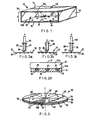
- FIG. 1 shows a multi-well assay plate, generally indicated by reference numeral 10, having a box-like construction with a rectangular cross-section.
- the assay plate 10 comprises an upper plate 12, a lower plate 14, and side and rear spacers 16,18,20 all of which are made of a transparent polycarbonate.
- the front of the box, indicated generally by the reference numeral 22, is open to the surrounding space.
- the spacers 16,18,20 are dimensioned to produce a space 21 of uniform spacing d between the opposed inner surfaces 12a,14a of the upper and lower plates 12,14. Spacing d is chosen such that a selected liquid is able to flow through the space 21 between the upper and lower plates 12,14 in a controlled manner by capillary or capillary-like action. Generally, d is less than 0.5mm.
- a small opening 23 extends through the upper plate 12 to communicate the inner space 21 with the exterior space surrounding the container. Opening 23 is located close to the rear wall 20 in order to prevent air-locks forming in the container during filling as will be described in more detail below.
- a regular array of wells or depressions 24 are formed in the upper surface 14a of the lower plate 14.
- the polycarbonate assay plate with wells 24 is produced by suitably moulding the lower plate 14 or by etching or pressing.
- the wells 24 are 2mm in diameter and 1mm deep and typically have a volume of 5 ⁇ l and any suitable number of wells may be provided.
- the wells are spaced 4mm apart (centre to centre).
- Figs. 2a to 2c illustrate the process by which the wells 24 of the assay plate 10 are filled with a liquid analyte 25.
- the end 26 of a syringe 28 containing the liquid analyte 25 is pressed into the opening 23 provided in the upper plate 12 of the container 10 (Fig. 2a) so as to form an air-tight seal between the periphery of the syringe and the inner surface of the opening 23.
- the plunger 30 of the syringe 28 is then depressed to force the liquid 25 through the opening 23 into the space 21 within the plate 10.
- Fig. 2a illustrate the process by which the wells 24 of the assay plate 10 are filled with a liquid analyte 25.
- the wells 24 of the plate 10 may be coated with an appropriate reactant. For example, if it is desired to conduct antigen-antibody reactions, the wells 24 are coated with an antigen. The remainder of the surface 14a is coated with a blocking agent to prevent antigen and antibodies from binding to surface 14a.
- a blocking agent to prevent antigen and antibodies from binding to surface 14a.
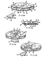
- FIG. 3 a second embodiment of the present invention which depicts a multi-well assay plate in the form of a disk 32 designed for use with a rotating scanning device having a CD player type format.
- the disk 32 shown in Fig. 3 comprises a pair of upper and lower circular plates 34,36 sandwiched together to provide a cylindrical space 38 therebetween. This space 38 is divided into eight sectors 40 by radially extending spacers 42.
- a plurality of wells 44 are provided in each sector 40 (one set of which is shown in broken outline) by forming the upper surface 36a of the lower circular plate 36 as described with reference to Fig. 1.
- the wells 44 are of the same size and are spaced as for Fig. 1.
- Each sector 40 provides a chamber or space 46 which can be filled independently via openings 48 provided through the top surface of each sector 40.
- the peripheral edge 50 of each sector 40 is open to the surrounding space to provide a vent for the sector 40 to allow liquid to flow through the space or chamber 46 by displacing air therefrom.
- the upper and/or lower plates 34,36 are made of transparent polycarbonate to enable a light beam to be scanned across the disk surface.
- the disk 32 is provided with a central hole 52 to enable the disk 32 to be mounted on a rotatable shaft.
- one of the surfaces of the upper or lower plates 34,36 may be provided with digitally encoded address information which can be read by the scanned light beam.
- This information may be encoded by way of "pits” and “lans” pressed or moulded into one of the plates. This address information can be used to provide accurate location information on the part of the disk which is begin scanned by the light beam.
- a disk assay plate 54 which comprises upper and lower circular transparent polycarbonate plates 56,58 which are spaced apart by a number of radially extending spacer walls 60 to create a plurality of disk sectors 62.
- the inner surfaces 56a,58a of the circular plates 56,58 are both planar.
- Each disk sector 62 is arranged to receive a sector plate insert 64 which is a transparent polycarbonate plate with a detachable handle 66 on the outer side to facilitate entry and removal of the plate insert 64 in the sector 62.
- the plate insert 64 and spacer wall 60 have respective recesses/projections (not shown in the interest of clarity) which allow the assay plate 64 to be inserted only in the correct orientation.
- the plate 64 has a groove 68, as shown in Fig. 4b for example, which allow the insert to be snap-fitted over a projection 70 upstanding from plate 58 into the sector.
- the thickness of the sector insert plate 64 is marginally less than the spacing provided between the upper and lower plates 56,58 so that the plate insert 64 can be pressed/fitted into one of the disk sector 62 to define a liquid receiving chamber or space 73 between the upper surface 64a of the insert plate 64 and the lower surface 56a of the upper disk plate 56. Openings 72 are provided through the upper plate 56 into each disk sector 64 whilst the space 70 between the radially outermost peripheral edge 74 of the insert plate 64 and the upper plate 56 provides a further vent or filling opening into the disk sector 64.
- the surface 64a of the insert plate 64 is provided with a plurality of wells 76 as described with respect to Fig. 1.
- the wells are 2mm in diameter, 1mm in depth and 4mm apart (spaced between centres). These wells are filled by introducing liquid into the disk sector 64 through the upper opening 72 to fill space 70 and subsequently withdrawing the liquid through the same opening as previously described.
- Fig. 5 of the drawings depicts assay apparatus for conducting an assay on reactions carried out using the assay plate structures of the already described embodiments.
- the assay apparatus will be described in combination with the preferred embodiment shown in Figs. 4a,b with like numerals referring to like parts.
- the apparatus includes a suitable automatic fluid filling/withdrawal system, generally indicated by reference numeral 80, which operates a syringe 82 to dispense/retrieve fluid from a reservoir 84 via the openings 72 into the space 70 between the plate surface 56a and the surface 64a of each sector plate 64.
- the fluid can of course be dispensed and retrieved manually if desired. This is achieved for each sector by rotating the disk plate 54 to a suitable position to allow fluid filling/withdrawal.
- the plates are pre-prepared with various reagents, e.g.
- antigens are inserted in the appropriate wells 76, as described with reference to Figs. 4a,4b.
- the plates are first flooded with fluid carrying antibodies and withdrawal of the fluid leaves the antibody/antigen reagents filling the wells 76 resulting in a reaction.
- the disk sector plate 54 is more suitable for conducting a variety of different assays, e.g. antigen/antibody assays for different patients, i.e. one patient/sector.
- the opening through which the liquid analyte is introduced may be provided through the lower plate of the multi-well container. More than one opening can be used for faster flooding. This opening may be arranged to receive the tip of a syringe needle.
- the vent opening may also be provided in any one of the walls of the container although it is preferably provided in a peripheral wall.
- the opening 22 may be provided by a single opening 22 or by a series of openings or vents as shown in Fig. 4d for example.
- a laser may be used with CD optics instead of the microscope and video camera for the embodiment of Fig. 4.
- the upper planar surface 56 can have sector covers connected to a lower surface or central boss by a hinge, for example an integrated living hinge 90 at the inner radius to allow each disk sector 62 to be pivotably raised and lowered and allow sector plates 64 to be inserted into each sector.
- the well size and spacing may be varied as required, for example the wells could be 3mm in diameter; 1.5mm apart and spaced 5.5mm between centre. The exact size and spacing is a matter of choice consistent with the requirement that fluid is retained in the wells after withdrawal as described above.
- the wells could also be filled during flooding of the space depending on the well size, type of plastic and fluid properties. However, liquid will still be retained in the wells upon withdrawal of the liquid.
- the structure and inserts made may be of any suitable optically transmissive plastic, such as polystyrene or perspex (TM).
- the handle 66 may be integrated with or detachable from plate 64. As shown in Fig. 4a the radially extending ribs may have radial shoulders 92 to define a recess 94 for receiving the plate 64 also defining the spacing height between the surface 64a of the plate 64 and the underside 56a for receiving the liquid. Suitable materials may be used to coat the interior of the sectors to aid fluid movement as described with reference to silicone above.
- Suitable materials may be used to increase the hydrophobicity of liquid across the sector and hydrophilicity to and movement of liquid into the desired locations, e.g. wells.
- the wells may be coated with a suitable optical reflective material to enhance the reflection of light and observation of reactions occurring within the wells and, similarly, lenses may be located in the top or bottom light transmissive plate to improve optical assessment of the reaction.
- These lenses may be moulded into the upper or lower plates during the manufacture as is well known in plastic moulding processes. Separate optical elements may be used instead, if appropriate.
- the wells are absent from the upper surface of the plate and that plate retains its planar surface to enable a thin, uniform layer of liquid to be introduced into the space between the upper disk plate and the insert plate.
- An insoluble substrate with reagent or reagents e.g. an antigen
- each insert may be slid into the space between the insert and the upper plate 22 of the disk following filling of the wells.
- the lower surface of the lid may be arranged to be flush with the surface of the insert so as to close off each well. This prevents liquid from being thrown out of the wells during spinning of the disk during automated reading and analysis.
- the invention has use in immunoassay applications including tests for sexually transmitted diseases, parasites, allergens, cancer markers and cardiac markers, either in laboratories or at point-of-care locations, for example medical practitioners offices or the like.
- Other applications of the invention are in chemical and biochemical assays. Examples of such assays include immunoassay, clinical biochemistry tests, nucleic acid analysis and receptor ligand interactions.
- Immunoassay application include tests designed to detect infectious organisms, viruses, parasites as well as endogenous analytes such as circulating hormone levels and cancer markers.
- Examples of chemical analysis include measure of phosphate and nitrate levels in water, environmental and industrial monitoring including potable and waste water and process monitoring. The system could be used in a variety of settings including clinical laboratories, doctor's and veterinary surgeries as well as industrial and research laboratories.
Landscapes
- Health & Medical Sciences (AREA)
- Chemical & Material Sciences (AREA)
- Hematology (AREA)
- Immunology (AREA)
- Life Sciences & Earth Sciences (AREA)
- Engineering & Computer Science (AREA)
- Analytical Chemistry (AREA)
- General Health & Medical Sciences (AREA)
- Chemical Kinetics & Catalysis (AREA)
- Molecular Biology (AREA)
- Clinical Laboratory Science (AREA)
- Biomedical Technology (AREA)
- Urology & Nephrology (AREA)
- Physics & Mathematics (AREA)
- General Physics & Mathematics (AREA)
- Cell Biology (AREA)
- Food Science & Technology (AREA)
- Medicinal Chemistry (AREA)
- Biotechnology (AREA)
- Biochemistry (AREA)
- Microbiology (AREA)
- Pathology (AREA)
- Automatic Analysis And Handling Materials Therefor (AREA)
- Optical Measuring Cells (AREA)
- Analysing Materials By The Use Of Radiation (AREA)
- Apparatus Associated With Microorganisms And Enzymes (AREA)
- Sampling And Sample Adjustment (AREA)
- Radar Systems Or Details Thereof (AREA)
- Investigating Or Analysing Biological Materials (AREA)
Abstract
Description
The data for the above assay is shown in Fig. 6a and is graphically represented in Fig. 6b which is reproducible and is representative of a large number of experiments (712).
Claims (50)
- An optically transparent structure for conducting assays comprising one or more chambers, each having an upper surface and a lower spaced opposed surface, said upper and lower surfaces defining a space therebetween, the lower surface having a plurality of surface locations bearing a hydrophilic coating, the spacing between said upper and lower surfaces being sufficiently small to facilitate fluid flow by capillary action of a fluid introduced into said space to cover all of the locations bearing a hydrophilic coating.
- The structure of claim 1 including at least one opening providing access to said space from an external location.
- The structure of claim 1 wherein areas of said lower surface between said locations having hydrophobic coatings.
- The structure of claim 1 wherein said surfaces are provided by respective upper and lower plates of an optical disc.
- The structure of claim 2 wherein said one opening providing access to said space is provided through either the upper or lower surface.
- The structure of claim 1 including digitally encoded address information provided for optical inspection thereof from exteriorly of said structure.
- The structure of claim 2 wherein said opening for providing access to said space is provided to receive the end of a liquid injecting device, and said one opening forms a substantially air-tight seal around said end.
- The structure of claim 1 wherein the structure is a disc which includes upper and lower circular plates, the internal surfaces of which respectively define said upper and lower opposed surfaces.
- The structure of claim 8 wherein a first opening is provided for access to said space from an external location and second opening is provided at a peripheral edge of the disc to vent said space.
- The structure of claim 8 wherein the space between the upper and lower plates is subdivided, by one or more dividing walls, to provide a plurality of spaces, and each space being provided with a fluid introduction opening and a vent opening to enable independent access to each space.
- The structure of claim 10 wherein the dividing walls are radially extending.
- The structure of claim 8 wherein at least one of the upper and lower plates forming the structure is transparent to enable optical inspection of the surface locations from outside the structure, and the other of the upper and lower plates includes a reflecting surface.
- The structure of claim 1 arranged to receive one or more inserts.
- The structure of claim 1 wherein the structure is provided as a sector of a disc.
- The structure of claim 14 wherein the structure is made of plastic and said one or more inserts is provided to be snap-fitted onto the disc.
- The structure of claim 15 wherein the structure and the disc include lock and key portions to allow the structure to be snap-fitted to the disc in a correct orientation only.
- The structure of claim 1 including one or more lenses to improve the optical inspection of said surface locations.
- The structure of claim 17 wherein said one or more lenses are molded into said structure.
- A multi-reaction site assay plate structure comprising an upper surface and a lower opposed surface, said upper and lower surfaces defining a space therebetween, the lower surface having a plurality of separate reaction sites, the reaction sites being treated to increase the hydrophilicity thereof, and the lower surface being treated to increase the hydrophobicity of the surface other than at said reaction sites, the spacing between said upper and lower surfaces being sufficiently small to facilitate the flow of fluid in said space by capillary action of a fluid introduced into said space through said opening to cover all of the sites, the sites being such that when excess fluid is subsequently withdrawn through the one or another opening some of said liquid is left at said sites.
- The assay plate structure of claim 19 including at least one opening providing access to said space from an external location.
- The assay plate structure of claim 20 wherein said opening providing access to said space is provided to receive the end of a liquid injecting device, and said opening forms a substantially air-tight seal around said end.
- The assay plate structure of claim 19 wherein the structure is an optically transparent disc which includes upper and lower circular plates, the internal surfaces of which respectively define said upper and lower opposed surfaces.
- The assay plate structure of claim 22 wherein a second opening is provided at a peripheral edge of the disc.
- The assay plate structure of claim 23 wherein the space between the upper and lower plates is subdivided, by one or more dividing walls, to provide a plurality of spaces, each space being provided with a fluid introduction opening and a vent opening to enable each space to be independently accessed.
- The assay plate structure of claim 22 wherein at least one of the upper and lower plates forming the structure are transparent to enable optical inspection of the sites from outside the structure.
- The assay plate structure of claim 25 wherein the other of the upper and lower plates includes a reflecting surface.
- The assay plate structure of claim 19 wherein the plate structure includes digitally encoded address information.
- An optically transparent disc for use with an optical reader, said disc comprising:an internal surface having a reaction site to be optically inspected by said reader; anda lens in said disc to improve optical inspection of said sites.
- The disc of claim 28 wherein said lens is molded into said disc as a part of said disc.
- The disc of claim 28 wherein said disc includes digitally encoded address information provided for optical inspection by said reader.
- The disc of anyone of claim 28 through 30 wherein said internal surface is provided within a chamber within said disc, said chamber having an upper surface spaced above said internal surface so as to facilitate fluid flow within said chamber by capillary action of a fluid introduced into said chamber.
- An optically transparent disc comprising digitally encoded address information;one or more fluid flow chambers, each of said one or more chambers defining a space therein to facilitate fluid flow throughout said space by capillary action of a fluid introduced into said space;a first opening providing access to said space from a location external of said disc; anda second opening for venting displacement of fluids from said space.
- The disc of claim 32 wherein said first opening providing access to said space is provided to receive the end of a liquid injecting device, and said first opening forms a substantially air-tight seal around said end.
- The disc of claim 32 wherein a surface within said chamber is treated to increase the hydrophobicity of such surface.
- The disc of claim 32 including upper and lower circular plates, the internal surfaces of which respectively define said space.
- The disc of claim 32 wherein said second opening is provided at a peripheral edge of the disc.
- The optical disc structure of claim 35 wherein the space between the upper and lower plates is subdivided, by one or more dividing walls, to provide a plurality of spaces, and each of said spaces being provided with a fluid introduction opening and a vent opening to enable each space to be independently accessed and vented.
- The optical disc structure of claim 37 wherein the dividing walls are radially extending.
- The optical disc structure of claim 35 wherein at least one of the upper and lower plates forming the structure are transparent to enable optical inspection of the one or more chambers from outside the structure.
- The optical disc structure of claim 39 wherein the other of the upper and lower plates includes a reflecting surface.
- The optical disc structure of claim 32 wherein the disc is arranged to receive one or more inserts, each of which includes one of said fluid flow chambers.
- An assay structure for use in conducting optical assays of a fluid analyte, the structure comprising:a disc for rotation about a central axis, the disc including optically readable digitally encoded address information provided therein for optical inspection thereof from externally of said disc and said disc being sub-divided into one or more disc sectors;one or more disc inserts arranged to be received by a respective disc sectors and to be retained therein,the structure further including one or more openings through the disc to provide , at least one opening for each disc sector for fluid communication with a disc insert received in said sector.
- The assay structure of claim 42 wherein a vent opening is provided in said disc for each disc sector around the periphery thereof.
- The assay structure of claim 42 wherein the one or more disc inserts are snap-fitted to the disc.
- The assay structure of claim 42 wherein the disc inserts and the disc include lock and key portions to allow the inserts to be snap-fitted to the disc in a correct orientation only.
- The assay structure of claim 42 wherein the disc and inserts are made of optically transmissive plastic.
- An optical disc for use in conducting optical assays of a fluid analyte, the disc comprising:optically readable digitally encoded address information; andsaid disc being divided into one or more disc sectors, each of said sectors being provided to receive a disc insert.
- The optical disc of claim 47 wherein a disc sector is provided with upper and lower plates spaced apart a sufficiently shallow distance to facilitate the flow of a fluid between said plates by capillary action.
- The optical disc of claim 48 including one or more disc inserts received in a respective disc sector.
- The optical disc of claim 49 wherein said disc sectors and disc inserts are provided to allow each of said inserts to be snap-fitted to said respective sector.
Applications Claiming Priority (3)
| Application Number | Priority Date | Filing Date | Title |
|---|---|---|---|
| GBGB9620934.1A GB9620934D0 (en) | 1996-10-08 | 1996-10-08 | Multi-well containers |
| GB9620934 | 1996-10-08 | ||
| EP97943992A EP0938382B1 (en) | 1996-10-08 | 1997-10-08 | Apparatus and method for conducting assays |
Related Parent Applications (1)
| Application Number | Title | Priority Date | Filing Date |
|---|---|---|---|
| EP97943992A Division EP0938382B1 (en) | 1996-10-08 | 1997-10-08 | Apparatus and method for conducting assays |
Publications (2)
| Publication Number | Publication Date |
|---|---|
| EP1188482A2 true EP1188482A2 (en) | 2002-03-20 |
| EP1188482A3 EP1188482A3 (en) | 2004-05-19 |
Family
ID=10801090
Family Applications (2)
| Application Number | Title | Priority Date | Filing Date |
|---|---|---|---|
| EP97943992A Expired - Lifetime EP0938382B1 (en) | 1996-10-08 | 1997-10-08 | Apparatus and method for conducting assays |
| EP01123697A Withdrawn EP1188482A3 (en) | 1996-10-08 | 1997-10-08 | Apparatus & method for conducting assays |
Family Applications Before (1)
| Application Number | Title | Priority Date | Filing Date |
|---|---|---|---|
| EP97943992A Expired - Lifetime EP0938382B1 (en) | 1996-10-08 | 1997-10-08 | Apparatus and method for conducting assays |
Country Status (10)
| Country | Link |
|---|---|
| US (2) | US7387898B1 (en) |
| EP (2) | EP0938382B1 (en) |
| CN (1) | CN1108874C (en) |
| AT (1) | ATE234154T1 (en) |
| AU (1) | AU724660B2 (en) |
| DE (1) | DE69719782T2 (en) |
| GB (1) | GB9620934D0 (en) |
| IL (1) | IL130042A0 (en) |
| NZ (1) | NZ335863A (en) |
| WO (1) | WO1998015356A1 (en) |
Cited By (2)
| Publication number | Priority date | Publication date | Assignee | Title |
|---|---|---|---|---|
| CN102639246A (en) * | 2009-10-22 | 2012-08-15 | 吉哈德·波耐科 | Test assembly for photometric measuring device and photometric measuring method for sample liquid |
| WO2016102071A1 (en) * | 2014-12-23 | 2016-06-30 | Testo Ag | Analysis method, discoid sample holder and use of a sample holder |
Families Citing this family (56)
| Publication number | Priority date | Publication date | Assignee | Title |
|---|---|---|---|---|
| US6327031B1 (en) | 1998-09-18 | 2001-12-04 | Burstein Technologies, Inc. | Apparatus and semi-reflective optical system for carrying out analysis of samples |
| GB9418981D0 (en) | 1994-09-21 | 1994-11-09 | Univ Glasgow | Apparatus and method for carrying out analysis of samples |
| US6342349B1 (en) | 1996-07-08 | 2002-01-29 | Burstein Technologies, Inc. | Optical disk-based assay devices and methods |
| GB9620934D0 (en) * | 1996-10-08 | 1996-11-27 | Molecular Drives Limited | Multi-well containers |
| EP1044375B1 (en) * | 1997-12-30 | 2005-12-14 | Remacle, José | Method comprising capture molecule fixed on disc surface |
| US8337753B2 (en) | 1998-05-01 | 2012-12-25 | Gen-Probe Incorporated | Temperature-controlled incubator having a receptacle mixing mechanism |
| ES2286750T3 (en) | 1998-05-01 | 2007-12-01 | Gen-Probe Incorporated | DEVICE FOR SHAKING THE LIQUID CONTENT OF A CONTAINER. |
| GB9809943D0 (en) * | 1998-05-08 | 1998-07-08 | Amersham Pharm Biotech Ab | Microfluidic device |
| US6888951B1 (en) | 1999-08-23 | 2005-05-03 | Nagaoka & Co., Ltd. | Methods and apparatus for analyzing operational and analyte data acquired from optical disc |
| EP1369699A1 (en) * | 1999-10-15 | 2003-12-10 | PE Corporation (NY) | System and method for filling a substrate with a liquid sample |
| US6272939B1 (en) * | 1999-10-15 | 2001-08-14 | Applera Corporation | System and method for filling a substrate with a liquid sample |
| US6760298B2 (en) | 2000-12-08 | 2004-07-06 | Nagaoka & Co., Ltd. | Multiple data layer optical discs for detecting analytes |
| US7079468B2 (en) | 2000-12-08 | 2006-07-18 | Burstein Technologies, Inc. | Optical discs for measuring analytes |
| AU2002239554A1 (en) * | 2000-12-08 | 2002-06-18 | Burstein Technologies, Inc. | Optical disc assemblies for performing assays |
| US7054258B2 (en) | 2000-12-08 | 2006-05-30 | Nagaoka & Co., Ltd. | Optical disc assemblies for performing assays |
| US7157047B2 (en) * | 2001-02-09 | 2007-01-02 | Pss Bio Instruments, Inc. | Device for containing, reacting and measuring, and method of containing, reacting and measuring |
| NL1017374C2 (en) * | 2001-02-15 | 2002-08-16 | Univ Delft Tech | Device for carrying out a reaction, as well as a method for carrying out a reaction in the device. |
| US7759067B2 (en) | 2001-03-19 | 2010-07-20 | Gyros Patent Ab | Method for determining the amount of an analyte with a disc-shaped microfluidic device |
| US20030077627A1 (en) * | 2001-07-19 | 2003-04-24 | Worthington Mark Oscar | Transmissive optical disc assemblies for performing physical measurements and methods relating thereto |
| DE10262157B4 (en) * | 2002-02-01 | 2006-11-09 | Fraunhofer-Gesellschaft zur Förderung der angewandten Forschung e.V. | Plate for use in cryogenic storage of biological specimens has wells, into which specimens are placed, fits into cover in same way as drawer of matchbox, and is held in position by e.g. studs and recesses |
| DE10262208B4 (en) * | 2002-02-01 | 2008-04-03 | Fraunhofer-Gesellschaft zur Förderung der angewandten Forschung e.V. | Sample carrier for a variety of cryoprobes |
| US7785782B2 (en) | 2002-12-12 | 2010-08-31 | Novartis Vaccines And Diagnostics, Inc. | Device and method for in-line blood testing using biochips |
| IL154677A0 (en) | 2003-02-27 | 2003-09-17 | Univ Bar Ilan | A method and apparatus for manipulating an individual cell |
| JP2007502218A (en) | 2003-05-23 | 2007-02-08 | ユィロス・パテント・アクチボラグ | Hydrophilic / hydrophobic surface |
| US7888110B2 (en) | 2003-06-26 | 2011-02-15 | Seng Enterprises Ltd. | Pico liter well holding device and method of making the same |
| US9200245B2 (en) | 2003-06-26 | 2015-12-01 | Seng Enterprises Ltd. | Multiwell plate |
| US7273591B2 (en) * | 2003-08-12 | 2007-09-25 | Idexx Laboratories, Inc. | Slide cartridge and reagent test slides for use with a chemical analyzer, and chemical analyzer for same |
| WO2005074893A1 (en) | 2004-02-03 | 2005-08-18 | Chemagis Ltd. | Stable amorphous forms of montelukast sodium |
| JP2005257337A (en) * | 2004-03-09 | 2005-09-22 | Brother Ind Ltd | Inspection object receiver, inspection device, and inspection method |
| US20080063251A1 (en) * | 2004-07-07 | 2008-03-13 | Mordechai Deutsch | Method and Device for Identifying an Image of a Well in an Image of a Well-Bearing |
| US7403647B2 (en) | 2004-09-13 | 2008-07-22 | Seng Enterprises Ltd. | Method for identifying an image of a well in an image of a well-bearing component |
| DE202006012937U1 (en) * | 2006-08-23 | 2007-12-27 | LÖRSCH, Johannes | Holding device for samples to be examined, in particular chemical or biological substances or the like. |
| US9145540B1 (en) | 2007-11-15 | 2015-09-29 | Seng Enterprises Ltd. | Device for the study of living cells |
| EP2237887A2 (en) | 2007-12-26 | 2010-10-13 | Seng Enterprises Ltd. | Device for the study of living cells |
| US8446463B2 (en) * | 2008-08-22 | 2013-05-21 | Genprime, Inc. | Apparatus, method and article to perform assays using assay strips |
| EP2639587B1 (en) | 2010-11-08 | 2019-08-14 | Hitachi High-Technologies Corporation | Reaction plate assembly, reaction plate and nucleic acid analysis device |
| US9914968B2 (en) | 2012-09-26 | 2018-03-13 | Cepheid | Honeycomb tube |
| CA3235305A1 (en) | 2013-01-04 | 2014-07-10 | Meso Scale Technologies, Llc. | Assay apparatuses, methods and reagents |
| US10831013B2 (en) | 2013-08-26 | 2020-11-10 | S.D. Sight Diagnostics Ltd. | Digital microscopy systems, methods and computer program products |
| CN106660047B (en) * | 2014-02-18 | 2019-12-10 | 卓格瑞公司 | Porous separation device and reagent delivery apparatus |
| AU2016322966B2 (en) | 2015-09-17 | 2021-10-14 | S.D. Sight Diagnostics Ltd | Methods and apparatus for detecting an entity in a bodily sample |
| US11733150B2 (en) | 2016-03-30 | 2023-08-22 | S.D. Sight Diagnostics Ltd. | Distinguishing between blood sample components |
| US11307196B2 (en) | 2016-05-11 | 2022-04-19 | S.D. Sight Diagnostics Ltd. | Sample carrier for optical measurements |
| EP3455626B1 (en) | 2016-05-11 | 2025-08-06 | S.D. Sight Diagnostics Ltd. | Performing optical measurements on a sample |
| US10576475B2 (en) | 2016-09-15 | 2020-03-03 | Genprime, Inc. | Diagnostic assay strip cassette |
| AU2018369859B2 (en) * | 2017-11-14 | 2024-01-25 | S.D. Sight Diagnostics Ltd | Sample carrier for optical measurements |
| US11008627B2 (en) | 2019-08-15 | 2021-05-18 | Talis Biomedical Corporation | Diagnostic system |
| AU2020372024B2 (en) | 2019-10-22 | 2026-03-12 | S.D. Sight Diagnostics Ltd | Accounting for errors in optical measurements |
| BR112022011312A2 (en) | 2019-12-12 | 2022-08-23 | S D Sight Diagnostics Ltd | ANALYSIS OF AN ANALYTE DISPOSED IN A MEDIUM |
| MX2022007127A (en) | 2019-12-12 | 2022-07-11 | S D Sight Diagnostics Ltd | Artificial generation of color blood smear image. |
| AU2020400400B2 (en) | 2019-12-12 | 2026-03-19 | S.D. Sight Diagnostics Ltd | Detecting platelets in a blood sample |
| WO2022136848A1 (en) * | 2020-12-22 | 2022-06-30 | Oxford Immune Algorithmics Ltd | Wafer for carrying biological sample |
| JP2024077768A (en) * | 2022-11-29 | 2024-06-10 | 博訊生物科技股▲分▼有限公司 | Automatic cell freezing and thawing equipment and rack carrier used therein |
| US12610944B2 (en) | 2022-12-21 | 2026-04-28 | Drsignal Biotechnology Co., Ltd. | Automatic cell cryopreservation and thawing apparatus |
| WO2024211906A1 (en) * | 2023-04-06 | 2024-10-10 | University Of Florida Research Foundation, Incorporated | Multi-well plates and methods of use |
| WO2025096875A1 (en) * | 2023-11-03 | 2025-05-08 | Generate Biomedicines, Inc. | High-throughput electrochemical sensing device, system, and related methods |
Family Cites Families (37)
| Publication number | Priority date | Publication date | Assignee | Title |
|---|---|---|---|---|
| SE399768B (en) | 1975-09-29 | 1978-02-27 | Lilja Jan E | CYVETT FOR SAMPLING, MIXING OF, THE SAMPLE WITH A REAGENTS AND DIRECT PERFORMANCE OF, SPECIAL OPTICAL, ANALYSIS OF THE SAMPLE MIXED WITH THE REAGENTS |
| GB1572596A (en) * | 1976-12-06 | 1980-07-30 | Opto Electronic Displays Ltd | Apparatus and method for innoculation |
| US4077845A (en) * | 1977-04-20 | 1978-03-07 | Miles Laboratories, Inc. | Disposable inoculation device and process of using same |
| US4195060A (en) * | 1978-02-08 | 1980-03-25 | Abbott Laboratories | Liquid reagent cartridge cuvette |
| US5496520A (en) * | 1982-01-08 | 1996-03-05 | Kelton; Arden A. | Rotary fluid manipulator |
| US4483925A (en) * | 1982-12-30 | 1984-11-20 | Becton, Dickinson And Company | Liquid removal device |
| GB8321239D0 (en) | 1983-08-05 | 1983-09-07 | Orbec Ltd | Innoculating means |
| US4961906A (en) * | 1984-04-12 | 1990-10-09 | Fisher Scientific Company | Liquid handling |
| US4596695A (en) | 1984-09-10 | 1986-06-24 | Cottingham Hugh V | Agglutinographic reaction chamber |
| US4900513A (en) * | 1986-07-11 | 1990-02-13 | Beckman Instruments, Inc. | Sample loading apparatus |
| US4722598A (en) * | 1986-12-04 | 1988-02-02 | Max M. Ford | Diagnostic microscope slide having multiple sample wells and cover |
| US5084397A (en) * | 1988-04-11 | 1992-01-28 | Miles Inc. | Method and apparatus for controlled reagent deposition in reaction cassettes and the like |
| US5281540A (en) * | 1988-08-02 | 1994-01-25 | Abbott Laboratories | Test array for performing assays |
| CA2028829A1 (en) * | 1989-03-07 | 1990-09-08 | Minoru Takase | Analyzer of liquid sample and analyzing method of liquid sample using said analyzer |
| AU642444B2 (en) * | 1989-11-30 | 1993-10-21 | Mochida Pharmaceutical Co., Ltd. | Reaction vessel |
| US5041266A (en) * | 1989-12-21 | 1991-08-20 | Hoffmann-La Roche Inc. | Tray for immunometric determinations |
| US5066465A (en) | 1989-12-27 | 1991-11-19 | Olympus Optical Co., Ltd. | Reaction apparatus |
| US5167922A (en) * | 1990-04-27 | 1992-12-01 | Pb Diagnostic Systems Inc. | Assay cartridge |
| ES2057904T3 (en) * | 1990-06-15 | 1994-10-16 | Chiron Corp | ASSEMBLY AND TEST APPARATUS, SELF-CONTAINED AND COMPLETE IN THEIR SAME. |
| US5182082A (en) * | 1991-01-23 | 1993-01-26 | Becton, Dickinson And Company | Multiple aliquot device for distributing a liquid solution into a well |
| JP3193443B2 (en) * | 1992-04-24 | 2001-07-30 | オリンパス光学工業株式会社 | Automatic analyzer |
| AU690124B2 (en) | 1993-06-09 | 1998-04-23 | Gamera Bioscience Corporation | Magnetic cycle reaction |
| JPH07113872A (en) * | 1993-10-13 | 1995-05-02 | Shigeo Baba | Method and apparatus for measuring beta emitter |
| CH687592A5 (en) * | 1993-10-18 | 1997-01-15 | Eidgenoess Munitionsfab Thun | Mehrgefaessanordnung for instrumental analysis. |
| KR970702375A (en) | 1994-03-24 | 1997-05-13 | 알렉미안 | A DNA MELTOMETER AND METHODS OF USE THEREOF |
| US5686271A (en) | 1994-06-09 | 1997-11-11 | Gamera Bioscience Corporation | Apparatus for performing magnetic cycle reaction |
| GB9418981D0 (en) * | 1994-09-21 | 1994-11-09 | Univ Glasgow | Apparatus and method for carrying out analysis of samples |
| US5585069A (en) * | 1994-11-10 | 1996-12-17 | David Sarnoff Research Center, Inc. | Partitioned microelectronic and fluidic device array for clinical diagnostics and chemical synthesis |
| US5955352A (en) * | 1994-12-22 | 1999-09-21 | Showa Yakuhin Kako Co., Ltd. | Instruments for chemical and microbiological tests |
| US5700655A (en) * | 1995-11-14 | 1997-12-23 | Idexx Laboratories, Inc. | Method for quantification of biological material in a sample |
| AU702403B2 (en) | 1995-12-05 | 1999-02-18 | Gamera Bioscience | Devices and methods for using centripetal acceleration to drive fluid movement in a microfluidics system with on-board informatics |
| GB9620934D0 (en) * | 1996-10-08 | 1996-11-27 | Molecular Drives Limited | Multi-well containers |
| US6143496A (en) * | 1997-04-17 | 2000-11-07 | Cytonix Corporation | Method of sampling, amplifying and quantifying segment of nucleic acid, polymerase chain reaction assembly having nanoliter-sized sample chambers, and method of filling assembly |
| USD403077S (en) * | 1997-05-12 | 1998-12-22 | Neogen Corporation | Microorganism culture tray |
| DE69816663T2 (en) * | 1997-10-27 | 2004-04-15 | Idexx Laboratories, Inc. | DEVICE FOR DETERMINING ANALYTES IN SOLUTIONS |
| US6027695A (en) * | 1998-04-01 | 2000-02-22 | Dupont Pharmaceuticals Company | Apparatus for holding small volumes of liquids |
| US6027873A (en) * | 1999-03-19 | 2000-02-22 | Genencor International, Inc. | Multi-through hole testing plate for high throughput screening |
-
1996
- 1996-10-08 GB GBGB9620934.1A patent/GB9620934D0/en active Pending
-
1997
- 1997-10-08 IL IL13004297A patent/IL130042A0/en unknown
- 1997-10-08 EP EP97943992A patent/EP0938382B1/en not_active Expired - Lifetime
- 1997-10-08 NZ NZ335863A patent/NZ335863A/en unknown
- 1997-10-08 DE DE69719782T patent/DE69719782T2/en not_active Expired - Fee Related
- 1997-10-08 US US09/284,421 patent/US7387898B1/en not_active Expired - Fee Related
- 1997-10-08 AU AU45642/97A patent/AU724660B2/en not_active Ceased
- 1997-10-08 EP EP01123697A patent/EP1188482A3/en not_active Withdrawn
- 1997-10-08 CN CN97180429A patent/CN1108874C/en not_active Expired - Fee Related
- 1997-10-08 WO PCT/GB1997/002708 patent/WO1998015356A1/en not_active Ceased
- 1997-10-08 AT AT97943992T patent/ATE234154T1/en not_active IP Right Cessation
-
2008
- 2008-06-17 US US12/140,691 patent/US20090068064A1/en not_active Abandoned
Cited By (7)
| Publication number | Priority date | Publication date | Assignee | Title |
|---|---|---|---|---|
| CN102639246A (en) * | 2009-10-22 | 2012-08-15 | 吉哈德·波耐科 | Test assembly for photometric measuring device and photometric measuring method for sample liquid |
| CN102639246B (en) * | 2009-10-22 | 2015-03-04 | 吉哈德·波耐科 | Test assembly for photometric measuring device and photometric measuring method for sample liquid |
| WO2016102071A1 (en) * | 2014-12-23 | 2016-06-30 | Testo Ag | Analysis method, discoid sample holder and use of a sample holder |
| CN107206374A (en) * | 2014-12-23 | 2017-09-26 | 特斯托欧洲股份两合公司 | Test method, disc-shaped specimen carrier and application of the specimen carrier |
| RU2721533C2 (en) * | 2014-12-23 | 2020-05-19 | ТЕСТО СЕ унд Ко. КГаА | Disc-shaped sample holder, sample processing method and use of sample holder |
| US11007521B2 (en) | 2014-12-23 | 2021-05-18 | Testo SE & Co. KGaA | Analysis method, discoid sample holder and use of a sample holder |
| US11654430B2 (en) | 2014-12-23 | 2023-05-23 | Testo SE & Co. KGaA | Analysis method, discoid sample holder and use of a sample holder |
Also Published As
| Publication number | Publication date |
|---|---|
| EP0938382A1 (en) | 1999-09-01 |
| AU4564297A (en) | 1998-05-05 |
| IL130042A0 (en) | 2000-02-29 |
| CN1108874C (en) | 2003-05-21 |
| EP0938382B1 (en) | 2003-03-12 |
| DE69719782D1 (en) | 2003-04-17 |
| EP1188482A3 (en) | 2004-05-19 |
| NZ335863A (en) | 2000-11-24 |
| AU724660B2 (en) | 2000-09-28 |
| DE69719782T2 (en) | 2004-03-25 |
| US7387898B1 (en) | 2008-06-17 |
| WO1998015356A1 (en) | 1998-04-16 |
| CN1239905A (en) | 1999-12-29 |
| GB9620934D0 (en) | 1996-11-27 |
| ATE234154T1 (en) | 2003-03-15 |
| US20090068064A1 (en) | 2009-03-12 |
Similar Documents
| Publication | Publication Date | Title |
|---|---|---|
| EP0938382B1 (en) | Apparatus and method for conducting assays | |
| JP3985872B2 (en) | container | |
| US5698406A (en) | Disposable device in diagnostic assays | |
| EP0034049B1 (en) | Test device for analysis of a plurality of analytes | |
| US7799558B1 (en) | Ligand binding assays on microarrays in closed multiwell plates | |
| US8097450B2 (en) | Thin film chemical analysis apparatus and analysis method using the same | |
| US7931868B2 (en) | Device for the manipulation of limited quantities of liquids | |
| US5399486A (en) | Disposable unit in diagnostic assays | |
| US20080274451A1 (en) | Body for flow-through cells and the use thereof | |
| JP2004361421A (en) | container | |
| JP2005010179A (en) | container | |
| JP3472306B2 (en) | Method and apparatus for treating a fluid | |
| US7863037B1 (en) | Ligand binding assays on microarrays in closed multiwell plates | |
| JP2731423B2 (en) | Rotary cuvette | |
| US6582929B2 (en) | Method for minimizing optical interference during antibiotic susceptibility readings in a microbiological analyzer | |
| US20040184965A1 (en) | Testing cup | |
| JP2004519235A (en) | Liquid flow and control in biological test arrays | |
| BR112021000974A2 (en) | multiplexed sample plate | |
| CZ178499A3 (en) | Method of carrying out analyses and apparatus for making the same | |
| JP2004361422A (en) | container |
Legal Events
| Date | Code | Title | Description |
|---|---|---|---|
| PUAI | Public reference made under article 153(3) epc to a published international application that has entered the european phase |
Free format text: ORIGINAL CODE: 0009012 |
|
| 17P | Request for examination filed |
Effective date: 20011024 |
|
| AC | Divisional application: reference to earlier application |
Ref document number: 938382 Country of ref document: EP |
|
| AK | Designated contracting states |
Kind code of ref document: A2 Designated state(s): AT BE CH DE DK ES FI FR GB GR IE IT LI LU MC NL PT SE |
|
| AX | Request for extension of the european patent |
Free format text: AL PAYMENT 20011029;LT PAYMENT 20011029;LV PAYMENT 20011029;RO PAYMENT 20011029;SI PAYMENT 20011029 |
|
| RIC1 | Information provided on ipc code assigned before grant |
Ipc: 7G 01N 33/543 B Ipc: 7B 01L 3/00 A |
|
| PUAL | Search report despatched |
Free format text: ORIGINAL CODE: 0009013 |
|
| AK | Designated contracting states |
Kind code of ref document: A3 Designated state(s): AT BE CH DE DK ES FI FR GB GR IE IT LI LU MC NL PT SE |
|
| AX | Request for extension of the european patent |
Extension state: AL LT LV RO SI |
|
| AKX | Designation fees paid |
Designated state(s): AT BE CH DE DK ES FI FR GB GR IE IT LI LU MC NL PT SE |
|
| AXX | Extension fees paid |
Extension state: SI Payment date: 20011029 Extension state: RO Payment date: 20011029 Extension state: LV Payment date: 20011029 Extension state: LT Payment date: 20011029 Extension state: AL Payment date: 20011029 |
|
| 17Q | First examination report despatched |
Effective date: 20050407 |
|
| RAP1 | Party data changed (applicant data changed or rights of an application transferred) |
Owner name: BURSTEIN TECHNOLOGIES, INC. |
|
| RAP1 | Party data changed (applicant data changed or rights of an application transferred) |
Owner name: NAGAOKA & CO., LTD. Owner name: BURSTEIN TECHNOLOGIES, INC. |
|
| STAA | Information on the status of an ep patent application or granted ep patent |
Free format text: STATUS: THE APPLICATION IS DEEMED TO BE WITHDRAWN |
|
| 18D | Application deemed to be withdrawn |
Effective date: 20071211 |