EP1195880A1 - Verfahren zur Erhöhung der Positioniergenauigkeit eines relativ zu einem Stator bewegbar angeordneten Elements - Google Patents
Verfahren zur Erhöhung der Positioniergenauigkeit eines relativ zu einem Stator bewegbar angeordneten Elements Download PDFInfo
- Publication number
- EP1195880A1 EP1195880A1 EP00810916A EP00810916A EP1195880A1 EP 1195880 A1 EP1195880 A1 EP 1195880A1 EP 00810916 A EP00810916 A EP 00810916A EP 00810916 A EP00810916 A EP 00810916A EP 1195880 A1 EP1195880 A1 EP 1195880A1
- Authority
- EP
- European Patent Office
- Prior art keywords
- sensor
- sensors
- stator
- error
- target position
- Prior art date
- Legal status (The legal status is an assumption and is not a legal conclusion. Google has not performed a legal analysis and makes no representation as to the accuracy of the status listed.)
- Granted
Links
- 238000000034 method Methods 0.000 title claims description 20
- 230000002708 enhancing effect Effects 0.000 title 1
- 238000004519 manufacturing process Methods 0.000 description 5
- 230000001419 dependent effect Effects 0.000 description 2
- 238000001514 detection method Methods 0.000 description 2
- 238000010276 construction Methods 0.000 description 1
- 238000011161 development Methods 0.000 description 1
- 230000018109 developmental process Effects 0.000 description 1
- 230000005415 magnetization Effects 0.000 description 1
- 238000005259 measurement Methods 0.000 description 1
- 230000003287 optical effect Effects 0.000 description 1
- 230000000737 periodic effect Effects 0.000 description 1
Images


Classifications
-
- H—ELECTRICITY
- H02—GENERATION; CONVERSION OR DISTRIBUTION OF ELECTRIC POWER
- H02K—DYNAMO-ELECTRIC MACHINES
- H02K41/00—Propulsion systems in which a rigid body is moved along a path due to dynamo-electric interaction between the body and a magnetic field travelling along the path
- H02K41/02—Linear motors; Sectional motors
- H02K41/03—Synchronous motors; Motors moving step by step; Reluctance motors
- H02K41/031—Synchronous motors; Motors moving step by step; Reluctance motors of the permanent magnet type
-
- H—ELECTRICITY
- H02—GENERATION; CONVERSION OR DISTRIBUTION OF ELECTRIC POWER
- H02K—DYNAMO-ELECTRIC MACHINES
- H02K29/00—Motors or generators having non-mechanical commutating devices, e.g. discharge tubes or semiconductor devices
- H02K29/06—Motors or generators having non-mechanical commutating devices, e.g. discharge tubes or semiconductor devices with position sensing devices
- H02K29/08—Motors or generators having non-mechanical commutating devices, e.g. discharge tubes or semiconductor devices with position sensing devices using magnetic effect devices, e.g. Hall-plates, magneto-resistors
Definitions
- the invention relates to a method for increasing the Positioning accuracy of a relative to a stator movably arranged element according to the preamble of independent claim.
- stator-side manufacturing tolerances are still relative well measured and for example in the processor or the Electronics of the linear motor are taken into account accordingly can be inhomogeneous, for example magnetized magnets of the runner - if at all - only possible with a lot of effort. But they are common Deviations of the runner from the target position by the inhomogeneous magnetization of the individual magnets of the rotor originate, much more dominant than those of Manufacturing tolerances of the stator arise, and the tolerances on the stator side can be measured anyway be compensated.
- Fig. 1 is an example of the course of a deviation the actual position of the rotor of a linear motor graphically displayed from its target position, with the Ordinate the deviation of the actual position of the Runner is plotted from its target position, and on the Abscissa the target position of the runner.
- the invention seeks to remedy this and a method propose which one - in the case of the linear motor - with Determination of the position error of the runner on simple Way is possible. Generally speaking, an easy one Determination of the position error of the movable element can be done.
- the conditions in considered a linear motor as an application example for the Method according to the invention, but without this Want to limit application to linear motors.
- the method can e.g. with rotary motors are used or generally in devices or Systems in which a movable element with sensors moved relative to a stator (fixed part of the device) is, wherein sensors are arranged in the stator for detection the position of the movable element.
- the actual course of the position error i.e. the Deviation from the actual position of the runner Linear motor from its target position, which for example is output by a display of the linear motor, shown.
- the position error shown in Fig. 1 is not determined with the aid of the method according to the invention been (but was e.g. measured).
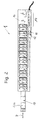
- FIG. 2 shows a linear motor 1 in a strong simplified representation, with the exception of the stator .10 nor the sensors 11 and 12 for determining the position of the Runner 13 can recognize, as well as electronics 14. Die Permanent magnets 130 of rotor 13 are only here shown in dashed lines, but they represent the Sensor which, when the rotor 13 moves in the Sensors 11 and 12 cause corresponding sensor signals.
- the sensors 11 and 12 can be used, for example, as Hall sensors be trained.
- FIG. 3 is a section of a stator shown as the sensors 11 and 12 for example are arranged, namely at a distance a from each other. If the rotor with its permanent magnets (in Fig. 3 not shown) on the sensors 11 and 12 in the direction of Arrows P moved past, as this when extending and retracting the Is the case, the sensors 11 and 12 corresponding sensor signals caused.
- FIG. 5 shows the spatial distance A, the two successive sensor signals of the same size of the corresponds to the first and second sensors 11 and 12, respectively. you recognizes that this distance A varies depending on is the target position of the runner.
- the course of the in Fig. 5th The curve shown is explained as follows: begins one at the target position zero (zero position of the rotor), so a very specific encoder excites that in this target position Sensor signal S11 (FIG. 5) in the first sensor 11 (FIG. 3). Becomes then the runner extended from the zero position, so it must first be extended a certain way, until exactly the same sensor in the second sensor 12 (FIG. 3) produces a sensor signal S12 of the same size as it is in the zero position of the rotor in the first sensor 11 has caused.
- the distance A between two sensor signals same size can be determined because the sensor signal S12 of the second sensor has not yet reached the value has which the encoder in the first sensor 11 in the Has caused the rotor to zero.
- the distance A is as large as the actual distance a of the two sensors 11 and 12 in the stator, which yes of the Construction is known or can be measured (in other words, you take for this area an error from zero or the error in this area is cleaned up with other methods).
- Fig. 6 now shows the course of the position error F as it determined with the aid of the method according to the invention and after the end of the calibration run at the actual Positioning of the runner is taken into account.
- the error F is zero at the beginning (he is simply assumed to be zero, as previously explained) until the runner has moved so far from the zero position, that the sensor signal S12 of the second sensor 12 (FIG. 3) is the same size as the sensor signal S11 of the first sensor 11 (Fig. 3) in the zero position of the rotor.
- the error F - starting from the zero position of the rotor when extending - as follows: As soon as the sensor signal S12 of the second sensor 12 is the same is as large as the sensor signal S11 in the zero position of the Distance A is determined. This distance is A nothing but the difference between the first Target position (here: zero position) and the second Target position (this is the position from which the Electronics "believes" that the runner is in this position actually located). To correct the position error of the Runner in this second position (that's the one Position in which the sensor signal S12 of the sensor 12 is the same size as the sensor signal S11 in the To be able to determine the zero position of the rotor) must the distance A the error in the first position - here the Zero position - be known.
- the error is in the second position of the However, Läufer determined that the error in the associated first position of the runner (that's the one Position in which the immediately preceding and from same signal of the first sensor Sensor 11 was the same size as the sensor signal S12 of the second sensor 12 in the second position) is determined. If this error is known in the first position, it becomes this error the difference between the distance A and the actual distance a of the sensors 11 and 12 is added. On this way you get the error in the second Position of the runner. If you do this successively for everyone "second" positions of the runner, you get the Course of the error F, as shown in Fig. 6. This error F thus determined is then after the end of Calibration run when positioning the runner takes into account what, for example, the basic software or by the respective application software can.
- the error in the first position of the runner (this is the position at which is the same as the sensor signal S11 of the first sensor 11 is as large as the sensor signal S12 of the second sensor S12 at the point at which the error is to be determined) weighted, for example with a factor of 0.75.
- This can cause tendencies to oscillate the error F, stimulated by outliers (small disturbances) in the Sensor signal detection can be reduced or suppressed. This makes the error determination procedure more stable.
- the application of the Process not only limited to linear motors, but is generally suitable for devices where a movable element relative to a stator (fixed Element) is movable and its position can be precisely determined have to be.
- the donors also do not have to be mandatory be magnetic and the sensors must accordingly not necessarily be magnetic field sensors, but can for example, on an optical or mechanical principle based. This is only in the application of the linear motor typically the case.
- the procedure is suitable for example also for rotary systems (e.g. for systems, where there is a very precise positioning of the rotor arrives).
- the sensors with which during the Calibration run of the position error is determined can be the same sensors, which later - after successful calibration - in the operation of the linear motor as Position sensors to determine the position of the runner can be used, but separate ones can also be used Calibration sensors are used.
- the calibration can also be carried out during operation or be tracked in between.
Landscapes
- Engineering & Computer Science (AREA)
- Physics & Mathematics (AREA)
- Chemical & Material Sciences (AREA)
- Combustion & Propulsion (AREA)
- Electromagnetism (AREA)
- Power Engineering (AREA)
Abstract
Description
- Fig. 1
- ein Beispiel für die Abweichung (Fehler) der tatsächlichen Position des Läufers eines Linearmotors von seiner Sollposition,
- Fig. 2
- ein Ausführungsbeispiel eines Linearmotors,
- Fig. 3
- einen Ausschnitt aus dem Stator eines Linearmotors mit zwei Sensoren zur Erfassung der Position des Läufers,
- Fig. 4
- den Verlauf der Sensorsignale,
- Fig. 5
- den Verlauf des räumlichen Abstandes, der zwei gleich grossen und aufeinander folgenden Sensorsignalen entspricht, welche durch denselben Geber hervorgerufen werden,
- Fig. 6
- den Verlauf des aufgrund des erfindungsgemässen Verfahrens ermittelten Fehlers der Sollposition (Abweichung der Sollposition von der tatsächlichen Position)
- Fig. 7
- den Verlauf des Fehlers der Sollposition aus Fig. 6, wobei jedoch nur eine bestimmte Anzahl von diskreten Werten gespeichert wird.
Claims (9)
- Verfahren zur Erhöhung der Positioniergenauigkeit eines relativ zu einem Stator (10) bewegbar angeordneten Elements (13) , wobei im Stator (10) mindestens zwei Sensoren (11,12) vorgesehen sind, ein erster (11) und ein zweiter (12) Sensor, die in Bezug auf die Bewegungsrichtung (P) des bewegbar angeordneten Elements (13) im Stator (10) in einem Abstand (a) voneinander angeordnet sind, und wobei das relativ zum Stator (10) bewegbar angeordnete Element (13) mit Gebern (130) versehen ist, die zusammen mit dem bewegbaren Element (13) mitbewegbar sind und bei einer ausfahrenden Bewegung des Elements (13) relativ zum Stator (10) zuerst in dem ersten Sensor (11) und dann bei fortschreitender Bewegung des Elements in dem zweiten Sensor (12) jeweils ein Sensorsignal (S11,S12) hervorrufen,
dadurch gekennzeichnet, dass zunächst in einem Kalibrierlauf das bewegbare Element (13) über den gesamten möglichen Bereich der Bewegung bewegt wird und während dieser Bewegung die Sensorsignale (S11,S12) des ersten (11) und des zweiten (12) Sensors sowie die zugehörigen Sollpositionen des bewegbaren Elements (13) erfasst werden, dass dann der räumliche Abstand (A) ermittelt wird, der zwei gleich grossen aufeinander folgenden und durch denselben Geber hervorgerufenen Sensorsignalen (S11,S12) des ersten (11) und des zweiten (12) Sensors entspricht, und dass aus dem so ermittelten räumlichen Abstand (A) , dem tatsächlichen Sensorabstand (a) und den zugehörigen Sollpositionen dann der Fehler (F) der Sollposition des bewegbaren Elements ermittelt und bei der Positionierung des bewegbaren Elements (13) berücksichtigt wird. - Verfahren nach Anspruch 1, bei welchem die Ermittlung des Fehlers (F) an einer bestimmten Sollposition des bewegbaren Elements (13) derart erfolgt, dass das Sensorsignal (S12) des zweiten Sensors (12) an der bestimmten Sollposition ausgelesen wird, danach diejenige Sollposition ausgelesen wird, bei der der erste Sensor (11) ein gleich grosses unmittelbar vorausgehendes Sensorsignal (S11) aufweist, danach der Positionsfehler (F) des Läufers an dieser Sollposition ausgelesen wird, und dann zu diesem Positionsfehler (F) die Differenz zwischen dem zuvor ermittelten räumlichen Abstand (A), bei dem die beiden Sensoren (11,12) ein gleich grosses Sensorsignal (S11,S12) aufweisen, und dem tatsächlichen Abstand (a) der Sensoren (11,12), addiert wird.
- Verfahren nach Anspruch 2, bei welchem der Positionsfehler an derjenigen Sollposition, bei welcher der erste Sensor (11) ein gleich grosses Sensorsignal (S11) aufweist wie bei der bestimmten Sollposition, gewichtet wird.
- Verfahren nach einem der vorangehenden Ansprüche, bei welchem dann, wenn der Betrag der Steigung der Sensorsignale (S11,S12) einen vorgebbaren Wert unterschreitet, anstelle einer Ermittlung des räumlichen Abstands (A) eine Interpolation zwischen dem vorhergehenden und dem nachfolgenden Wert für den Abstand (A) vorgenommen wird.
- Verfahren nach einem der vorangehenden Ansprüche, bei welchem der tatsächliche Fehler (F) der Sollposition des bewegbaren Elements (13) nicht für jede einzelne Sollposition in einem Speicher abgelegt wird, sondern nur für eine bestimmte Anzahl von Sollpositionen, und dass dann, wenn der Fehler für eine Sollposition benötigt wird, die zwischen zwei im Speicher abgelegten Sollpositionen liegt, eine Interpolation vorgenommen wird.
- Vorrichtung mit einem Stator (10) und einem relativ zu diesem Stator (10) bewegbaren Element (13), wobei im Stator (10) mindestens zwei Sensoren (11,12) vorgesehen sind, ein erster (11) und ein zweiter (12) Sensor, die in Bezug auf die Bewegungsrichtung (P) des bewegbar angeordneten Elements im Stator in einem Abstand (a) voneinander angeordnet sind, und wobei das relativ zum Stator bewegbare Element (13) mit Gebern (130) versehen ist, die zusammen mit dem bewegbaren Element (13) mitbewegbar sind und bei einer ausfahrenden Bewegung des Elements (13) relativ zum Stator (10) zuerst in dem ersten Sensor (11) und dann bei fortschreitender Bewegung in dem zweiten Sensor (12) jeweils ein Sensorsignal (S11,S12) hervorrufen, dadurch gekennzeichnet, dass Mittel (14) vorgesehen sind zur Erfassung der Sensorsignale (S11,S12) des ersten (11) und des zweiten (12) Sensors sowie der zugehörigen Sollpositionen des bewegbaren Elements (13) und zur Ermittlung des räumlichen Abstands (A), welcher zwei gleich grossen aufeinander folgenden Sensorsignalen (S11,S12) des ersten (11) und des zweiten (12) Sensors entspricht, und dass Mittel (14) vorgesehen sind, welche aus dem so ermittelten räumlichen Abstand (A), dem tatsächlichen Sensorabstand (a) und den zugehörigen Sollpositionen dann den Fehler (F) der Sollposition des bewegbaren Elements (13) ermitteln und bei der Positionierung des bewegbaren Elements (13) berücksichtigen.
- Vorrichtung nach Anspruch 6, welche einen Linearmotor (1) mit einem Stator (10) und einem Läufer (13) umfasst, und bei welcher die Geber als Permanentmagnete (130) im Läufer angeordnet sind und die im Stator (10) angeordneten Sensoren (11,12) als Magnetfeldsensoren ausgebildet sind, insbesondere als Hall-Sensoren, und bei welcher die Mittel zur Erfassung der Sensorsignale und der zugehörigen Sollpositionen in einer Elektronik (14) vorgesehen sind, ebenso wie die Mittel, welche den räumlichen Abstand (A) ermitteln und welche dann den Fehler (F) der Sollposition ermitteln und bei der Positionierung des Läufers (13) berücksichtigen.
- Vorrichtung nach Anspruch 7, bei welcher die Mittel (14) zur Erfassung der Sensorsignale (S11,S12) und der zugehörigen Sollpositionen ebenso wie die Mittel (14), welche den räumlichen Abstand (A) ermitteln und welche dann den Fehler (F) der Sollposition ermitteln und bei der Positionierung des Läufers (13) berücksichtigen, in der Basis-Software und/oder in der Applikations-Software der Elektronik (14) vorgesehen sind.
- Vorrichtung nach einem der Ansprüche 6 bis 8, bei welcher die Sensoren (11,12) zur Ermittlung des Positionsfehlers (F) die gleichen Sensoren sind wie die Positionssensoren, welche im Betrieb die Position des beweglichen Elements bzw. des Läufers (13) bestimmen.
Priority Applications (3)
| Application Number | Priority Date | Filing Date | Title |
|---|---|---|---|
| DE50003742T DE50003742D1 (de) | 2000-10-04 | 2000-10-04 | Verfahren zur Erhöhung der Positioniergenauigkeit eines relativ zu einem Stator bewegbar angeordneten Elements |
| EP00810916A EP1195880B1 (de) | 2000-10-04 | 2000-10-04 | Verfahren zur Erhöhung der Positioniergenauigkeit eines relativ zu einem Stator bewegbar angeordneten Elements |
| US09/970,039 US6532791B2 (en) | 2000-10-04 | 2001-10-01 | Method for increasing the positioning accuracy of an element which is movably arranged relative to a stator |
Applications Claiming Priority (1)
| Application Number | Priority Date | Filing Date | Title |
|---|---|---|---|
| EP00810916A EP1195880B1 (de) | 2000-10-04 | 2000-10-04 | Verfahren zur Erhöhung der Positioniergenauigkeit eines relativ zu einem Stator bewegbar angeordneten Elements |
Publications (2)
| Publication Number | Publication Date |
|---|---|
| EP1195880A1 true EP1195880A1 (de) | 2002-04-10 |
| EP1195880B1 EP1195880B1 (de) | 2003-09-17 |
Family
ID=8174953
Family Applications (1)
| Application Number | Title | Priority Date | Filing Date |
|---|---|---|---|
| EP00810916A Expired - Lifetime EP1195880B1 (de) | 2000-10-04 | 2000-10-04 | Verfahren zur Erhöhung der Positioniergenauigkeit eines relativ zu einem Stator bewegbar angeordneten Elements |
Country Status (3)
| Country | Link |
|---|---|
| US (1) | US6532791B2 (de) |
| EP (1) | EP1195880B1 (de) |
| DE (1) | DE50003742D1 (de) |
Cited By (8)
| Publication number | Priority date | Publication date | Assignee | Title |
|---|---|---|---|---|
| EP1612920A3 (de) * | 2004-07-01 | 2008-07-16 | Tsunehiko Yamazaki | Positionssensor für einen Linearmotor |
| CN103288025A (zh) * | 2012-02-28 | 2013-09-11 | 克朗斯股份公司 | 容器处理机和用于校准的方法 |
| EP2908098A1 (de) | 2014-02-18 | 2015-08-19 | Hexagon Technology Center GmbH | Lineargeber mit Kalibrierfunktionalität |
| EP2908100A1 (de) | 2014-02-18 | 2015-08-19 | Hexagon Technology Center GmbH | System zur Bestimmung von Relativpositionen |
| EP3376166A1 (de) * | 2017-03-13 | 2018-09-19 | B&R Industrial Automation GmbH | Verfahren zur bestimmung der absolutposition eines läufers eines linearmotors |
| DE102022110084A1 (de) | 2022-04-26 | 2023-10-26 | Sick Ag | Bestimmung der Position eines ersten Objekts relativ zu einem zweiten Objekt |
| WO2023208945A1 (de) | 2022-04-28 | 2023-11-02 | B&R Industrial Automation GmbH | Verfahren zur identifikation und kompensation eines positions-messfehlers |
| DE102023130003A1 (de) * | 2023-10-30 | 2025-04-30 | J.Schmalz Gmbh | Spannsystem umfassend eine Spannvorrichtung und eine Konsole |
Families Citing this family (20)
| Publication number | Priority date | Publication date | Assignee | Title |
|---|---|---|---|---|
| DE10162448B4 (de) * | 2001-01-12 | 2014-09-04 | Heidelberger Druckmaschinen Ag | Einrichtung zur Lageerfassung eines Läuferteils in einem Transportsystem |
| DE10316940B4 (de) * | 2003-04-12 | 2007-05-24 | Minebea Co., Ltd. | Meßverfahren an einem Elektromotor und Meßvorrichtung für einen Elektromotor zur Bestimmung von Abhebehöhe und/oder axialem Spiel |
| US7696748B2 (en) * | 2003-10-10 | 2010-04-13 | Jentek Sensors, Inc. | Absolute property measurements using electromagnetic sensors |
| US20060025951A1 (en) * | 2004-07-28 | 2006-02-02 | Philippe Noel | Method for calibrating a position sensor in an electric machine |
| US10338158B2 (en) | 2007-05-30 | 2019-07-02 | Infineon Technologies Ag | Bias magnetic field sensor |
| US10852367B2 (en) | 2007-05-30 | 2020-12-01 | Infineon Technologies Ag | Magnetic-field sensor with a back-bias magnet |
| DE102007025000B3 (de) | 2007-05-30 | 2008-12-11 | Infineon Technologies Ag | Magnetfeldsensor |
| US8283813B2 (en) | 2007-06-27 | 2012-10-09 | Brooks Automation, Inc. | Robot drive with magnetic spindle bearings |
| CN101855811B (zh) | 2007-06-27 | 2013-11-20 | 布鲁克斯自动化公司 | 具有提升能力和减少的齿槽特性的电机定子 |
| KR101660894B1 (ko) | 2007-06-27 | 2016-10-10 | 브룩스 오토메이션 인코퍼레이티드 | 다차원 위치 센서 |
| WO2009003193A1 (en) | 2007-06-27 | 2008-12-31 | Brooks Automation, Inc. | Position feedback for self bearing motor |
| US9752615B2 (en) * | 2007-06-27 | 2017-09-05 | Brooks Automation, Inc. | Reduced-complexity self-bearing brushless DC motor |
| US8823294B2 (en) | 2007-06-27 | 2014-09-02 | Brooks Automation, Inc. | Commutation of an electromagnetic propulsion and guidance system |
| JP2011514652A (ja) | 2007-07-17 | 2011-05-06 | ブルックス オートメーション インコーポレイテッド | チャンバ壁に一体化されたモータを伴う基板処理装置 |
| US8547083B2 (en) | 2008-09-25 | 2013-10-01 | Nti Ag | Apparatus for determination of the axial position of the armature of a linear motor |
| DE102012204917A1 (de) | 2012-03-27 | 2013-10-02 | Beckhoff Automation Gmbh | Positionserfassungsvorrichtung und Verfahren zum Erfassen einer Position eines beweglichen Elements einer Antriebsvorrichtung |
| DE102012204916A1 (de) | 2012-03-27 | 2013-10-02 | Beckhoff Automation Gmbh | Statorvorrichtung für einen Linearmotor und lineares Transportsystem |
| DE202012013152U1 (de) | 2012-03-27 | 2015-02-11 | Beckhoff Automation Gmbh | Statorvorrichtung für einen Linearmotor und lineares Transportsystem |
| NL2011427A (en) | 2012-10-01 | 2014-04-02 | Asml Netherlands Bv | A method for calibration of an encoder scale and a lithographic apparatus. |
| DK3391021T3 (da) * | 2015-12-16 | 2021-09-27 | Dynatest As | Nedbøjningsmåler med faldvægt |
Citations (4)
| Publication number | Priority date | Publication date | Assignee | Title |
|---|---|---|---|---|
| DE3829405A1 (de) * | 1988-08-30 | 1990-03-08 | Webasto Ag Fahrzeugtechnik | Betaetigungseinrichtung fuer elektromotorisch bewegbare teile von kraftfahrzeugen |
| EP0590384A2 (de) * | 1992-10-01 | 1994-04-06 | Robert Bosch Gmbh | Vorrichtung zur Lageregelung eines bewegbaren Teils |
| US5489845A (en) * | 1994-09-19 | 1996-02-06 | Ford Motor Company | Encoder system and method for determining absolute rotor position by taking a mid value of the multiple coil output sinusoidal signals |
| US5530303A (en) * | 1993-07-16 | 1996-06-25 | Nippon Thompson Co., Ltd. | Linear direct current motor |
Family Cites Families (5)
| Publication number | Priority date | Publication date | Assignee | Title |
|---|---|---|---|---|
| DE3024716C2 (de) * | 1980-06-30 | 1986-10-23 | Dr. Johannes Heidenhain Gmbh, 8225 Traunreut | Digitales Längen- oder Winkelmeßsystem |
| DE3244891C2 (de) * | 1982-12-04 | 1985-07-11 | Angewandte Digital Elektronik Gmbh, 2051 Brunstorf | Einrichtung zur berührungslosen Positionsmessung |
| DE3443176C1 (de) * | 1984-11-27 | 1990-11-15 | Angewandte Digital Elektronik Gmbh, 2051 Brunstorf | Verfahren zur Kalibrierung eines elektronischen Positionsgebers |
| DE4319322C2 (de) * | 1993-06-11 | 1998-04-23 | Heidenhain Gmbh Dr Johannes | Positionsmeßeinrichtung |
| US6097183A (en) * | 1998-04-14 | 2000-08-01 | Honeywell International Inc. | Position detection apparatus with correction for non-linear sensor regions |
-
2000
- 2000-10-04 DE DE50003742T patent/DE50003742D1/de not_active Expired - Lifetime
- 2000-10-04 EP EP00810916A patent/EP1195880B1/de not_active Expired - Lifetime
-
2001
- 2001-10-01 US US09/970,039 patent/US6532791B2/en not_active Expired - Fee Related
Patent Citations (4)
| Publication number | Priority date | Publication date | Assignee | Title |
|---|---|---|---|---|
| DE3829405A1 (de) * | 1988-08-30 | 1990-03-08 | Webasto Ag Fahrzeugtechnik | Betaetigungseinrichtung fuer elektromotorisch bewegbare teile von kraftfahrzeugen |
| EP0590384A2 (de) * | 1992-10-01 | 1994-04-06 | Robert Bosch Gmbh | Vorrichtung zur Lageregelung eines bewegbaren Teils |
| US5530303A (en) * | 1993-07-16 | 1996-06-25 | Nippon Thompson Co., Ltd. | Linear direct current motor |
| US5489845A (en) * | 1994-09-19 | 1996-02-06 | Ford Motor Company | Encoder system and method for determining absolute rotor position by taking a mid value of the multiple coil output sinusoidal signals |
Cited By (13)
| Publication number | Priority date | Publication date | Assignee | Title |
|---|---|---|---|---|
| EP1612920A3 (de) * | 2004-07-01 | 2008-07-16 | Tsunehiko Yamazaki | Positionssensor für einen Linearmotor |
| CN103288025A (zh) * | 2012-02-28 | 2013-09-11 | 克朗斯股份公司 | 容器处理机和用于校准的方法 |
| CN103288025B (zh) * | 2012-02-28 | 2015-06-17 | 克朗斯股份公司 | 容器处理机和用于校准的方法 |
| US9846063B2 (en) | 2014-02-18 | 2017-12-19 | Hexagon Technology Center Gmbh | Linear encoder having calibration functionality |
| EP2908100A1 (de) | 2014-02-18 | 2015-08-19 | Hexagon Technology Center GmbH | System zur Bestimmung von Relativpositionen |
| US9638550B2 (en) | 2014-02-18 | 2017-05-02 | Hexagon Technology Center Gmbh | Encoder and sensor system having plural sensors and encoder elements for determining relative positions |
| EP2908098A1 (de) | 2014-02-18 | 2015-08-19 | Hexagon Technology Center GmbH | Lineargeber mit Kalibrierfunktionalität |
| EP3376166A1 (de) * | 2017-03-13 | 2018-09-19 | B&R Industrial Automation GmbH | Verfahren zur bestimmung der absolutposition eines läufers eines linearmotors |
| US10476413B2 (en) | 2017-03-13 | 2019-11-12 | B&R Industrial Automation GmbH | Method for determining the absolute position of a rotor of a linear motor |
| DE102022110084A1 (de) | 2022-04-26 | 2023-10-26 | Sick Ag | Bestimmung der Position eines ersten Objekts relativ zu einem zweiten Objekt |
| DE102022110084B4 (de) * | 2022-04-26 | 2025-12-24 | Sick Ag | Bestimmung der Position eines ersten Objekts relativ zu einem zweiten Objekt |
| WO2023208945A1 (de) | 2022-04-28 | 2023-11-02 | B&R Industrial Automation GmbH | Verfahren zur identifikation und kompensation eines positions-messfehlers |
| DE102023130003A1 (de) * | 2023-10-30 | 2025-04-30 | J.Schmalz Gmbh | Spannsystem umfassend eine Spannvorrichtung und eine Konsole |
Also Published As
| Publication number | Publication date |
|---|---|
| DE50003742D1 (de) | 2003-10-23 |
| US20020049553A1 (en) | 2002-04-25 |
| US6532791B2 (en) | 2003-03-18 |
| EP1195880B1 (de) | 2003-09-17 |
Similar Documents
| Publication | Publication Date | Title |
|---|---|---|
| EP1195880B1 (de) | Verfahren zur Erhöhung der Positioniergenauigkeit eines relativ zu einem Stator bewegbar angeordneten Elements | |
| EP3376166B1 (de) | Verfahren zur bestimmung der absolutposition eines läufers eines linearmotors | |
| DE10037211B4 (de) | Lenkradstellungssensor | |
| DE10204427B4 (de) | Verfahren und Vorrichtung zur Kompensation dynamischer Fehlersignale eines Chopped-Hall-Sensors | |
| EP0555507B1 (de) | Wegmesseinrichtung | |
| DE602005002763T2 (de) | Kodierer und Steuervorrichtung für Motor | |
| EP1141660A1 (de) | Vorrichtung und verfahren zur messung der winkellage eines drehbaren körpers | |
| DE102010028333A1 (de) | Inkrementelles Multipositions-Erfassungssystem für ein umlaufendes elektromagnetisches Transfersystem | |
| EP3663722A1 (de) | Verfahren zur automatischen kalibrierung eines magnetischen sensors und magnetischer sensor | |
| EP0048851A2 (de) | Digitales elektrisches Längen- oder Winkelmess-system | |
| EP1510115A1 (de) | Bauelementegurt-transportrad, bauelementegurt-transportsystem und verfahren zum betreiben eines bauelementegurt-transportsystems | |
| EP2017627A2 (de) | Induktive drehzahlerkennung | |
| EP1770373A1 (de) | Absolutes Positionsmesssystem | |
| EP1006342B1 (de) | Markierungsverfahren von Messspuren | |
| DE10228581B4 (de) | Verfahren zum Korrigieren des Signals eines Nockenwellen-Sensors | |
| EP1321743A1 (de) | Längenmesssystem, bei dem ein Massstab relativ zur Position von beabstandeten Längesensoren bewegt wird | |
| EP2116814B1 (de) | Messeinrichtung zur Ermittlung einer Lage und/oder einer Geschwindigkeit | |
| DE3815530C2 (de) | ||
| EP0194611A2 (de) | Messeinrichtung | |
| EP3913349A1 (de) | Verfahren zur ermittlung der belastung einer antriebswelle | |
| DE102008004916A1 (de) | Verfahren zur Kalibrierung der Position eines Magnetfeldsensors | |
| DE4210934C1 (de) | ||
| EP0626299A1 (de) | Vorrichtung zur Positionsbestimmung eines an einer Schiene verfahrbaren Fahrzeuges | |
| DE102021118092A1 (de) | Encodersystem sowie Verfahren zur zumindest abschnittsweisen Linearisierung einer Maßverkörperung | |
| DE102008057672A1 (de) | Verfahren und Vorrichtung zur Kalibrierung von einem oder mehreren Sensoren eines Fahrzeuges |
Legal Events
| Date | Code | Title | Description |
|---|---|---|---|
| PUAI | Public reference made under article 153(3) epc to a published international application that has entered the european phase |
Free format text: ORIGINAL CODE: 0009012 |
|
| AK | Designated contracting states |
Kind code of ref document: A1 Designated state(s): AT BE CH CY DE DK ES FI FR GB GR IE IT LI LU MC NL PT SE Kind code of ref document: A1 Designated state(s): CH DE GB IT LI |
|
| AX | Request for extension of the european patent |
Free format text: AL;LT;LV;MK;RO;SI |
|
| 17P | Request for examination filed |
Effective date: 20020717 |
|
| AKX | Designation fees paid |
Free format text: CH DE GB IT LI |
|
| GRAH | Despatch of communication of intention to grant a patent |
Free format text: ORIGINAL CODE: EPIDOS IGRA |
|
| GRAS | Grant fee paid |
Free format text: ORIGINAL CODE: EPIDOSNIGR3 |
|
| GRAA | (expected) grant |
Free format text: ORIGINAL CODE: 0009210 |
|
| AK | Designated contracting states |
Kind code of ref document: B1 Designated state(s): CH DE GB IT LI |
|
| REG | Reference to a national code |
Ref country code: GB Ref legal event code: FG4D Free format text: NOT ENGLISH |
|
| REG | Reference to a national code |
Ref country code: CH Ref legal event code: EP |
|
| GBT | Gb: translation of ep patent filed (gb section 77(6)(a)/1977) | ||
| REG | Reference to a national code |
Ref country code: CH Ref legal event code: NV Representative=s name: A. BRAUN, BRAUN, HERITIER, ESCHMANN AG PATENTANWAE |
|
| REF | Corresponds to: |
Ref document number: 50003742 Country of ref document: DE Date of ref document: 20031023 Kind code of ref document: P |
|
| REG | Reference to a national code |
Ref country code: IE Ref legal event code: FG4D Free format text: GERMAN |
|
| REG | Reference to a national code |
Ref country code: IE Ref legal event code: FD4D |
|
| PLBE | No opposition filed within time limit |
Free format text: ORIGINAL CODE: 0009261 |
|
| STAA | Information on the status of an ep patent application or granted ep patent |
Free format text: STATUS: NO OPPOSITION FILED WITHIN TIME LIMIT |
|
| 26N | No opposition filed |
Effective date: 20040618 |
|
| REG | Reference to a national code |
Ref country code: CH Ref legal event code: PFA Owner name: NTI AG Free format text: NTI AG#TECHNOPARKSTRASSE 1#8005 ZUERICH (CH) -TRANSFER TO- NTI AG#TECHNOPARKSTRASSE 1#8005 ZUERICH (CH) |
|
| PGFP | Annual fee paid to national office [announced via postgrant information from national office to epo] |
Ref country code: CH Payment date: 20081024 Year of fee payment: 9 |
|
| PGFP | Annual fee paid to national office [announced via postgrant information from national office to epo] |
Ref country code: IT Payment date: 20081016 Year of fee payment: 9 |
|
| PGFP | Annual fee paid to national office [announced via postgrant information from national office to epo] |
Ref country code: GB Payment date: 20081007 Year of fee payment: 9 |
|
| REG | Reference to a national code |
Ref country code: CH Ref legal event code: PL |
|
| PGFP | Annual fee paid to national office [announced via postgrant information from national office to epo] |
Ref country code: DE Payment date: 20091229 Year of fee payment: 10 |
|
| PG25 | Lapsed in a contracting state [announced via postgrant information from national office to epo] |
Ref country code: LI Free format text: LAPSE BECAUSE OF NON-PAYMENT OF DUE FEES Effective date: 20091031 Ref country code: CH Free format text: LAPSE BECAUSE OF NON-PAYMENT OF DUE FEES Effective date: 20091031 |
|
| PG25 | Lapsed in a contracting state [announced via postgrant information from national office to epo] |
Ref country code: GB Free format text: LAPSE BECAUSE OF NON-PAYMENT OF DUE FEES Effective date: 20091004 |
|
| PG25 | Lapsed in a contracting state [announced via postgrant information from national office to epo] |
Ref country code: IT Free format text: LAPSE BECAUSE OF NON-PAYMENT OF DUE FEES Effective date: 20091004 |
|
| REG | Reference to a national code |
Ref country code: DE Ref legal event code: R119 Ref document number: 50003742 Country of ref document: DE Effective date: 20110502 |
|
| PG25 | Lapsed in a contracting state [announced via postgrant information from national office to epo] |
Ref country code: DE Free format text: LAPSE BECAUSE OF NON-PAYMENT OF DUE FEES Effective date: 20110502 |