EP1198885B1 - Elektronische antriebssteuerung - Google Patents
Elektronische antriebssteuerung Download PDFInfo
- Publication number
- EP1198885B1 EP1198885B1 EP00949356A EP00949356A EP1198885B1 EP 1198885 B1 EP1198885 B1 EP 1198885B1 EP 00949356 A EP00949356 A EP 00949356A EP 00949356 A EP00949356 A EP 00949356A EP 1198885 B1 EP1198885 B1 EP 1198885B1
- Authority
- EP
- European Patent Office
- Prior art keywords
- control mechanism
- drive control
- combination
- electronic drive
- mechanism according
- Prior art date
- Legal status (The legal status is an assumption and is not a legal conclusion. Google has not performed a legal analysis and makes no representation as to the accuracy of the status listed.)
- Expired - Lifetime
Links
Images



Classifications
-
- H—ELECTRICITY
- H01—ELECTRIC ELEMENTS
- H01H—ELECTRIC SWITCHES; RELAYS; SELECTORS; EMERGENCY PROTECTIVE DEVICES
- H01H47/00—Circuit arrangements not adapted to a particular application of the relay and designed to obtain desired operating characteristics or to provide energising current
- H01H47/22—Circuit arrangements not adapted to a particular application of the relay and designed to obtain desired operating characteristics or to provide energising current for supplying energising current for relay coil
- H01H47/32—Energising current supplied by semiconductor device
- H01H47/325—Energising current supplied by semiconductor device by switching regulator
-
- H—ELECTRICITY
- H01—ELECTRIC ELEMENTS
- H01H—ELECTRIC SWITCHES; RELAYS; SELECTORS; EMERGENCY PROTECTIVE DEVICES
- H01H47/00—Circuit arrangements not adapted to a particular application of the relay and designed to obtain desired operating characteristics or to provide energising current
- H01H47/002—Monitoring or fail-safe circuits
Definitions
- the invention relates to an electronic drive control according to the preamble of Claim 1.
- EP 0 789 378 A1 describes an electronic drive control for one Magnetic drive with pulse width modulation of the armature current is known. Operation of the Armature coil is made with a constant voltage.
- US-A-5 579 194 there is one electronic drive control for controlling a drive coil of a contactor described that a pulse width signal generated by a calculator and a Has semiconductor switch.
- the pulse width ratio is represented by a downstream pulse shaper stage changeable.
- the frequency of a pulse width modulator (PWM) or the T on time cannot be chosen arbitrarily. Due to the development of noise in the magnetic circuit due to the pulsing of the drive coil, in contrast to the pull-in control, in which this brief noise development is completely covered by the movement process of the entire drive, the PWM frequency for the holding operation must be set to a frequency which is outside the human Listening area. Frequencies outside the human hearing range are above 20 kHz. This corresponds to a period of 50 ⁇ s. The required current reduction to the holding mode would result in a relatively short T on time of, for example, 400 ns, taking into account reserve reserves and other factors.
- PWM pulse width modulator
- the object of the invention is therefore to provide an electronic drive control Preamble of claim 1 to create with a large Voltage range of the holding operation realized with as little loss and noise as possible can be.
- the object of the invention is characterized by the characterizing features of Claim 1 solved, while in the dependent claims particularly advantageous Developments of the invention are characterized.
- the holding pulses can be correspondingly finely graduated by the invention.
- the Holding power is minimized in a simple manner.
- Fig. 1 shows the drive coil 1 of a contactor with a free-wheeling diode 2, with a semiconductor switch 3 for the holding mode, a further semiconductor switch 4 for the tightening operation and the pulse shaper stage 5, which is the control input of the semiconductor element 3 is connected upstream.
- the temperature is already taken into account on the analog side of the voltage measurement, in that the gain factor of the operational amplifier 6 is influenced by a temperature-dependent resistance in such a way that the measured input voltage is multiplied by the reciprocal of the correction factor k T. This results in complete temperature compensation of the drive coil.
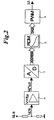
- the PWM determination is carried out by means of a map control, which is shown in FIG. 2.
- the PWM values are calculated in advance, taking into account all determinable, constant correction factors, and are stored as a fixed correction table in a data memory 8 of a microcontroller.
- the output value of an A / D converter 7, with which the input voltage is measured, serves as an address pointer, so that the associated T ON or T OFF time can be read directly from the data memory cell addressed in this way.
- the clock ratio of the PWM modulator 9 is not arbitrary, but rather can only be set as an integral multiple of the clock frequency or a variable derived therefrom.
- the microcontroller is operated with an oscillator of 10 MHz.
- the oscillator frequency is reduced internally again by a divider 10/1 to a clock frequency of 1 MHz, so that a minimum of 1 ⁇ s can be set as the shortest T ON time.
- the shortest T ON time that the microcontroller can deliver is therefore longer than the minimum time required for the PWM signal, so that an additional pulse shaping stage between the PWM output of the microcontroller and the semiconductor switch is required for the hold mode, with which the T ON time of the microcontroller can be reduced accordingly. Furthermore, this pulse shaping stage is required so that the T ON time can be resolved more finely in order to minimize the step size of the holding current and thus the holding power (P Halt ⁇ I Halt 2 ).
- FIG. 3 shows the structure of the pulse shaper stage 5 from FIG. 1.
- the negated PWM signal (open collector) of the microcontroller is connected here to a capacitor 11 via a decoupling diode 10.
- the voltage at the capacitor 11 is monitored via an inverter 12 with a Schmitt trigger input.
- the switching level is approx. 60% of the supply voltage V CC .
- With the falling edge of the PWM signal of the microcontroller up to four outputs are activated Q 1 - Q 4 of the microcontroller controlled with open collector. These outputs discharge the capacitor 11 via the stepped resistors R1 to R4. As soon as the voltage across the capacitor has dropped below the threshold voltage, the semiconductor switch 3 is activated via the inverter 12.
- the negated outputs Q 1 - Q 4 of the microcontroller can be switched to open-collector transistor stages 13 with discharge resistors R1-R4, the pulse width of the control signal of the semiconductor switch 3 being determinable by the PWM output and the RC combination.
Landscapes
- Engineering & Computer Science (AREA)
- Power Engineering (AREA)
- Relay Circuits (AREA)
- Dc-Dc Converters (AREA)
- Control Of Direct Current Motors (AREA)
- Control Of Electrical Variables (AREA)
Description
- Fig. 1
- eine Darstellung der Antriebsspule mit Halbleiterschaltem für Anzugund Haltebetrieb,
- Fig. 2
- eine Darstellung der Kennfeldsteuerung,
- Fig. 3
- eine Darstellung der Impulsformerstufe und
- Fig. 4
- ein Impuls- und Spannungsdiagramm.
Claims (6)
- Elektronische Antriebssteuerung zur Steuerung einer Antriebsspule (1) eines Schützes, die ein durch ein Rechenwerk erzeugtes Pulsweitensignal und mindestens einen Halbleiterschalter (3) aufweist, wobei das Pulsweitensignal durch eine nachgeschaltete Impulsformerstufe (5) veränderbar ist, dadurch gekennzeichnet, daß das negierte PWM-Signal eines Microkontrollers auf eine vorwählbare RC-Kombination (C, R1-R4) geschaltet wird, daß der Halbleiterschalter (3) durch einen der RC-Kombination nachgeschalteten Inverter (12) mit Schmitt-Trigger-Eingang ansteuerbar ist, daß die Vorwahl der RC-Kombination über mehrere Ausgänge (
Q 1 -Q 4) des Microkontrollers auf Openkollektor-Transistorstufen (13) der Entladewiderstände (R1-R4) der RC-Kombination (C, R1-R4) geschieht, wobei die Impulsbreite des Ansteuersignals des Halbleiterschalters (3) durch den PWM-Ausgang und die vorgewählte RC-Kombination bestimmt ist. - Elektronische Antriebssteuerung nach Anspruch 1, dadurch gekennzeichnet, daß vier Ausgänge des Microkontrollers (
Q 1 -Q 4) vorhanden sind, die mit entsprechender Abstufung der RC-Kombination (C, R1-R4) das PWM-Signal in 16 Stufen auflösen. - Elektronische Antriebssteuerung nach einem der vorhergehenden Ansprüche, dadurch gekennzeichnet, daß das Pulsweitenverhältnis von 1/50 auf 1/500 einstellbar ist.
- Elektronische Antriebssteuerung nach einem der vorhergehenden Ansprüche, dadurch gekennzeichnet, daß eine Filterung der Eingangsspannung über ein T-Filter erfolgt, das vor dem Microkontroller angeordnet ist.
- Elektronische Antriebssteuerung nach einem der vorhergehenden Ansprüche, dadurch gekennzeichnet, daß eine Kompensationsschaltung (6) zur Temperaturkompensation der Antriebsspule (1) vorhanden ist und daß die Kompensationsschaltung (6) einen Temperaturbeiwert aufweist, der etwa dem doppelten Temperaturbeiwert von Kupfer entspricht.
- Elektronische Antriebssteuerung nach einem der vorhergehenden Ansprüche, dadurch gekennzeichnet, daß der Microkontroller einen nicht-flüchtigen Datenspeicher (8) umfaßt, in dem eine Korrekturtabelle mit PWM-Werten abgelegt ist.
Applications Claiming Priority (3)
| Application Number | Priority Date | Filing Date | Title |
|---|---|---|---|
| DE19935045A DE19935045A1 (de) | 1999-07-26 | 1999-07-26 | Elektronische Antriebssteuerung |
| DE19935045 | 1999-07-26 | ||
| PCT/EP2000/006775 WO2001008307A1 (de) | 1999-07-26 | 2000-07-15 | Elektronische antriebssteuerung |
Publications (2)
| Publication Number | Publication Date |
|---|---|
| EP1198885A1 EP1198885A1 (de) | 2002-04-24 |
| EP1198885B1 true EP1198885B1 (de) | 2003-09-17 |
Family
ID=7916100
Family Applications (1)
| Application Number | Title | Priority Date | Filing Date |
|---|---|---|---|
| EP00949356A Expired - Lifetime EP1198885B1 (de) | 1999-07-26 | 2000-07-15 | Elektronische antriebssteuerung |
Country Status (7)
| Country | Link |
|---|---|
| US (1) | US6775114B1 (de) |
| EP (1) | EP1198885B1 (de) |
| JP (1) | JP2003505853A (de) |
| CN (1) | CN1167198C (de) |
| AU (1) | AU6274300A (de) |
| DE (2) | DE19935045A1 (de) |
| WO (1) | WO2001008307A1 (de) |
Cited By (1)
| Publication number | Priority date | Publication date | Assignee | Title |
|---|---|---|---|---|
| EP2407994A2 (de) | 2010-07-14 | 2012-01-18 | BSH Bosch und Siemens Hausgeräte GmbH | Verfahren zum Betreiben eines elektrischen Schalters in einem Haushaltsgerät und Haushaltsgerät mit einem elektrischen Schalter |
Families Citing this family (7)
| Publication number | Priority date | Publication date | Assignee | Title |
|---|---|---|---|---|
| EP1703639A1 (de) * | 2005-03-15 | 2006-09-20 | Genbond Enterprises Ltd. | Steuervorrichtung für Leistungsschaltung mit verbesserter Sicherheit |
| DE102007031995A1 (de) * | 2007-07-09 | 2009-01-15 | Moeller Gmbh | Steuervorrichtung für ein Schaltgerät mit Anzugs- und/oder Haltespule sowie Verfahren zum Steuern des durch die Spule fließenden Stroms |
| WO2011095223A1 (en) * | 2010-02-08 | 2011-08-11 | Siemens Aktiengesellschaft | Apparatus for an electromagnetic switching device |
| CN103262198B (zh) * | 2010-12-20 | 2016-01-13 | 西门子公司 | 用于电磁继电器的驱动电路 |
| DE102012222129A1 (de) * | 2012-12-04 | 2014-06-05 | Robert Bosch Gmbh | Verfahren zum Betrieb eines Ansteuerkreises eines elektromagnetischen Schalters |
| KR102692910B1 (ko) | 2019-03-11 | 2024-08-08 | 엘에스일렉트릭(주) | 전자접촉기의 코일 구동 장치 |
| KR102154635B1 (ko) | 2019-08-26 | 2020-09-10 | 엘에스일렉트릭(주) | 코일 구동 장치 |
Family Cites Families (15)
| Publication number | Priority date | Publication date | Assignee | Title |
|---|---|---|---|---|
| US3693029A (en) * | 1970-06-26 | 1972-09-19 | Francis J Niven Jr | Electrical compensation circuit utilizing two transistors connected in parallel |
| US5023527A (en) * | 1974-06-24 | 1991-06-11 | General Electric Company | Control circuits, electronically commutated motor systems and methods |
| US4157538A (en) * | 1977-11-21 | 1979-06-05 | The Singer Company | Correction circuit for a digital to synchro/resolver converter |
| DE3616356A1 (de) | 1986-05-15 | 1987-11-19 | Vdo Schindling | Verfahren und schaltungsanordnung zur ansteuerung eines einspritzventils |
| JPH03155211A (ja) * | 1989-11-14 | 1991-07-03 | Ono Sokki Co Ltd | 時定数切換装置 |
| JP3030076B2 (ja) | 1990-11-01 | 2000-04-10 | 三菱電機株式会社 | 電流制御回路 |
| DE9216041U1 (de) * | 1992-11-23 | 1993-01-14 | Mannesmann AG, 4000 Düsseldorf | Schaltungsanordnung zur Ansteuerung eines Relais |
| US5579194A (en) * | 1994-12-13 | 1996-11-26 | Eaton Corporation | Motor starter with dual-slope integrator |
| JPH09162031A (ja) | 1995-12-13 | 1997-06-20 | Sumitomo Electric Ind Ltd | パルス幅変調方式の電流制御装置及びその電流制御方法 |
| SE505747C2 (sv) * | 1996-02-07 | 1997-10-06 | Asea Brown Boveri | Kontaktorutrustning |
| US5694949A (en) * | 1996-08-06 | 1997-12-09 | Pacesetter, Inc. | Variable capacitance emulation circuit for electrophysiology diagnostic device |
| US5818678A (en) | 1997-10-09 | 1998-10-06 | Delco Electronics Corporation | Tri-state control apparatus for a solenoid having on off and PWM control modes |
| DE29812029U1 (de) * | 1998-07-07 | 1998-11-05 | Bucher, Siegfried, Dipl.-Ing.(FH), 78652 Deißlingen | Elektromechanisches Relais |
| DE29909901U1 (de) * | 1999-06-08 | 1999-09-30 | Moeller GmbH, 53115 Bonn | Elektronische Antriebssteuerung für einen Schützantrieb |
| DE29909904U1 (de) * | 1999-06-08 | 1999-09-30 | Moeller GmbH, 53115 Bonn | Antriebssteuerung |
-
1999
- 1999-07-26 DE DE19935045A patent/DE19935045A1/de not_active Withdrawn
-
2000
- 2000-07-15 CN CNB008095310A patent/CN1167198C/zh not_active Expired - Fee Related
- 2000-07-15 JP JP2001512706A patent/JP2003505853A/ja active Pending
- 2000-07-15 US US10/048,093 patent/US6775114B1/en not_active Expired - Fee Related
- 2000-07-15 EP EP00949356A patent/EP1198885B1/de not_active Expired - Lifetime
- 2000-07-15 AU AU62743/00A patent/AU6274300A/en not_active Abandoned
- 2000-07-15 DE DE50003748T patent/DE50003748D1/de not_active Expired - Lifetime
- 2000-07-15 WO PCT/EP2000/006775 patent/WO2001008307A1/de not_active Ceased
Cited By (4)
| Publication number | Priority date | Publication date | Assignee | Title |
|---|---|---|---|---|
| EP2407994A2 (de) | 2010-07-14 | 2012-01-18 | BSH Bosch und Siemens Hausgeräte GmbH | Verfahren zum Betreiben eines elektrischen Schalters in einem Haushaltsgerät und Haushaltsgerät mit einem elektrischen Schalter |
| DE102010031333A1 (de) | 2010-07-14 | 2012-01-19 | BSH Bosch und Siemens Hausgeräte GmbH | Verfahren zum Betreiben eines elektromagnetischen Schaltgerätes in einem Haushaltsgerät, Steuereinrichtung zum Durchführen des Verfahrens und Haushaltsgerät mit einer derartigen Steuereinrichtung |
| DE102010031333B4 (de) * | 2010-07-14 | 2012-03-15 | BSH Bosch und Siemens Hausgeräte GmbH | Verfahren zum Betreiben eines elektromagnetischen Schaltgerätes in einem Haushaltsgerät, Steuereinrichtung zum Durchführen des Verfahrens und Haushaltsgerät mit einer derartigen Steuereinrichtung |
| EP2407994A3 (de) * | 2010-07-14 | 2013-07-03 | BSH Bosch und Siemens Hausgeräte GmbH | Verfahren zum Betreiben eines elektrischen Schalters in einem Haushaltsgerät und Haushaltsgerät mit einem elektrischen Schalter |
Also Published As
| Publication number | Publication date |
|---|---|
| CN1167198C (zh) | 2004-09-15 |
| DE19935045A1 (de) | 2001-02-01 |
| WO2001008307A1 (de) | 2001-02-01 |
| DE50003748D1 (de) | 2003-10-23 |
| JP2003505853A (ja) | 2003-02-12 |
| EP1198885A1 (de) | 2002-04-24 |
| AU6274300A (en) | 2001-02-13 |
| CN1358350A (zh) | 2002-07-10 |
| US6775114B1 (en) | 2004-08-10 |
Similar Documents
| Publication | Publication Date | Title |
|---|---|---|
| EP0705482B1 (de) | Schaltungsanordnung zur ansteuerung eines schützes | |
| DE19920307A1 (de) | Elektrische Schaltung zum Steuern einer Last | |
| EP0392058A1 (de) | Schaltungsanordnung zur Ansteuerung mindestens eines elektromagnetishen Relais | |
| EP0685940A1 (de) | Pulsweitenmodulierter Schaltwandler zum Betrieb elektrischer Verbraucher | |
| EP1198885B1 (de) | Elektronische antriebssteuerung | |
| DE3926178A1 (de) | Aufweck-schaltungsanordnung fuer einen mikroprozessor | |
| EP1038212A1 (de) | Elektronische schaltungsandordnung zum beaufschlagen eines mikroprozessors mit weck- und aktionssignalen | |
| EP0471891A2 (de) | Schaltungsanordnung zur Ansteuerung einer Gruppe von Relais | |
| DE19935043B4 (de) | Schaltungsanordnung zur elektronischen Steuerung einer Antriebsspule | |
| DE69216141T2 (de) | Variable Pegeltreiberschaltung für periodische Ansteuerung einer kapazitiven Last | |
| DE10155969A1 (de) | Vorrichtung zur Ansteuerung eines elektromagnetischen Stellgliedes | |
| DE3107580C2 (de) | ||
| EP0590340B1 (de) | Schaltungsanordnung | |
| DE2952156A1 (de) | Spannungs-frequenz-wandler, insbesondere fuer die verwendung in elektrischen steuersystemen von kraftfahrzeugen | |
| EP1031182B1 (de) | Verfahren und schaltungsanordnung zur erzeugung eines pulsbreitenmodulierten stellsignals für einen gleichstromaktuator | |
| EP0899860B1 (de) | Leistungsendstufenschaltung mit PWM-Betrieb und Dauereinschaltbetrieb | |
| EP0126243B1 (de) | Schaltungsanordnung zum transformatorischen Ansteuern eines Schalttransistors | |
| DE2459841B2 (de) | Elektrische antriebs- und steuereinrichtung fuer mit ultraschall arbeitende zahnbehandlungsgeraete | |
| EP0289730A2 (de) | Vorrichtung zur Überwachung elektronischer Geräte | |
| DE2413173B2 (de) | Schaltungsanordnung zur Erzeugung einer geregelten Ausgangsspannung | |
| DE3624139A1 (de) | Schaltungsanordnung fuer die betaetigung eines verbrauchers mittels eines mikroprozessors | |
| DE3319943C2 (de) | Hochfrequenz-Impulsverstärker | |
| EP0543030A1 (de) | Integrierbare Schaltungsanordnung zur Ansteuerung eines mit Gleichstrom betriebenen Relais | |
| DE3125925A1 (de) | "kapazitiver annaeherungsschalter" | |
| DE2529633A1 (de) | Kontrollschaltung fuer eine batteriezustandsanzeige |
Legal Events
| Date | Code | Title | Description |
|---|---|---|---|
| PUAI | Public reference made under article 153(3) epc to a published international application that has entered the european phase |
Free format text: ORIGINAL CODE: 0009012 |
|
| 17P | Request for examination filed |
Effective date: 20010711 |
|
| AK | Designated contracting states |
Kind code of ref document: A1 Designated state(s): AT BE CH CY DE DK ES FI FR GB GR IE IT LI LU MC NL PT SE |
|
| AX | Request for extension of the european patent |
Free format text: AL;LT;LV;MK;RO;SI |
|
| GRAH | Despatch of communication of intention to grant a patent |
Free format text: ORIGINAL CODE: EPIDOS IGRA |
|
| GRAH | Despatch of communication of intention to grant a patent |
Free format text: ORIGINAL CODE: EPIDOS IGRA |
|
| GRAA | (expected) grant |
Free format text: ORIGINAL CODE: 0009210 |
|
| AK | Designated contracting states |
Kind code of ref document: B1 Designated state(s): CH DE FR IT LI SE |
|
| REG | Reference to a national code |
Ref country code: CH Ref legal event code: EP |
|
| REF | Corresponds to: |
Ref document number: 50003748 Country of ref document: DE Date of ref document: 20031023 Kind code of ref document: P |
|
| REG | Reference to a national code |
Ref country code: IE Ref legal event code: FG4D Free format text: GERMAN |
|
| REG | Reference to a national code |
Ref country code: CH Ref legal event code: NV Representative=s name: E. BLUM & CO. PATENTANWAELTE |
|
| REG | Reference to a national code |
Ref country code: SE Ref legal event code: TRGR |
|
| LTIE | Lt: invalidation of european patent or patent extension |
Effective date: 20030917 |
|
| REG | Reference to a national code |
Ref country code: IE Ref legal event code: FD4D |
|
| ET | Fr: translation filed | ||
| PLBE | No opposition filed within time limit |
Free format text: ORIGINAL CODE: 0009261 |
|
| STAA | Information on the status of an ep patent application or granted ep patent |
Free format text: STATUS: NO OPPOSITION FILED WITHIN TIME LIMIT |
|
| 26N | No opposition filed |
Effective date: 20040618 |
|
| REG | Reference to a national code |
Ref country code: CH Ref legal event code: PFA Owner name: MOELLER GMBH Free format text: MOELLER GMBH#HEIN-MOELLER-STRASSE 7-11#53115 BONN (DE) -TRANSFER TO- MOELLER GMBH#HEIN-MOELLER-STRASSE 7-11#53115 BONN (DE) |
|
| PGFP | Annual fee paid to national office [announced via postgrant information from national office to epo] |
Ref country code: CH Payment date: 20130806 Year of fee payment: 14 Ref country code: DE Payment date: 20130731 Year of fee payment: 14 Ref country code: SE Payment date: 20130708 Year of fee payment: 14 |
|
| PGFP | Annual fee paid to national office [announced via postgrant information from national office to epo] |
Ref country code: FR Payment date: 20130712 Year of fee payment: 14 |
|
| PGFP | Annual fee paid to national office [announced via postgrant information from national office to epo] |
Ref country code: IT Payment date: 20130716 Year of fee payment: 14 |
|
| REG | Reference to a national code |
Ref country code: DE Ref legal event code: R119 Ref document number: 50003748 Country of ref document: DE |
|
| REG | Reference to a national code |
Ref country code: CH Ref legal event code: PL |
|
| REG | Reference to a national code |
Ref country code: SE Ref legal event code: EUG |
|
| REG | Reference to a national code |
Ref country code: FR Ref legal event code: ST Effective date: 20150331 |
|
| PG25 | Lapsed in a contracting state [announced via postgrant information from national office to epo] |
Ref country code: CH Free format text: LAPSE BECAUSE OF NON-PAYMENT OF DUE FEES Effective date: 20140731 Ref country code: LI Free format text: LAPSE BECAUSE OF NON-PAYMENT OF DUE FEES Effective date: 20140731 Ref country code: IT Free format text: LAPSE BECAUSE OF NON-PAYMENT OF DUE FEES Effective date: 20140715 Ref country code: DE Free format text: LAPSE BECAUSE OF NON-PAYMENT OF DUE FEES Effective date: 20150203 |
|
| REG | Reference to a national code |
Ref country code: DE Ref legal event code: R119 Ref document number: 50003748 Country of ref document: DE Effective date: 20150203 |
|
| PG25 | Lapsed in a contracting state [announced via postgrant information from national office to epo] |
Ref country code: SE Free format text: LAPSE BECAUSE OF NON-PAYMENT OF DUE FEES Effective date: 20140716 Ref country code: FR Free format text: LAPSE BECAUSE OF NON-PAYMENT OF DUE FEES Effective date: 20140731 |