EP1199434A1 - A method of forming a building component from different materials - Google Patents
A method of forming a building component from different materials Download PDFInfo
- Publication number
- EP1199434A1 EP1199434A1 EP00650164A EP00650164A EP1199434A1 EP 1199434 A1 EP1199434 A1 EP 1199434A1 EP 00650164 A EP00650164 A EP 00650164A EP 00650164 A EP00650164 A EP 00650164A EP 1199434 A1 EP1199434 A1 EP 1199434A1
- Authority
- EP
- European Patent Office
- Prior art keywords
- tenon
- limb
- movement
- building component
- limbs
- Prior art date
- Legal status (The legal status is an assumption and is not a legal conclusion. Google has not performed a legal analysis and makes no representation as to the accuracy of the status listed.)
- Withdrawn
Links
- 238000000034 method Methods 0.000 title claims description 8
- 239000000463 material Substances 0.000 title description 7
- 230000015572 biosynthetic process Effects 0.000 claims abstract description 16
- 230000002265 prevention Effects 0.000 claims description 6
- 239000007769 metal material Substances 0.000 claims description 4
- 239000000853 adhesive Substances 0.000 claims description 3
- 230000001070 adhesive effect Effects 0.000 claims description 3
- 239000004020 conductor Substances 0.000 claims description 3
- 239000004033 plastic Substances 0.000 description 6
- 229920003023 plastic Polymers 0.000 description 6
- 239000004411 aluminium Substances 0.000 description 4
- 229910052782 aluminium Inorganic materials 0.000 description 4
- XAGFODPZIPBFFR-UHFFFAOYSA-N aluminium Chemical compound [Al] XAGFODPZIPBFFR-UHFFFAOYSA-N 0.000 description 4
- 238000012986 modification Methods 0.000 description 4
- 230000004048 modification Effects 0.000 description 4
- 239000002023 wood Substances 0.000 description 4
- 239000002131 composite material Substances 0.000 description 1
- 238000010276 construction Methods 0.000 description 1
- 238000012423 maintenance Methods 0.000 description 1
- 239000002184 metal Substances 0.000 description 1
- 229910052751 metal Inorganic materials 0.000 description 1
- 239000003973 paint Substances 0.000 description 1
Images
Classifications
-
- E—FIXED CONSTRUCTIONS
- E06—DOORS, WINDOWS, SHUTTERS, OR ROLLER BLINDS IN GENERAL; LADDERS
- E06B—FIXED OR MOVABLE CLOSURES FOR OPENINGS IN BUILDINGS, VEHICLES, FENCES OR LIKE ENCLOSURES IN GENERAL, e.g. DOORS, WINDOWS, BLINDS, GATES
- E06B3/00—Window sashes, door leaves, or like elements for closing wall or like openings; Layout of fixed or moving closures, e.g. windows in wall or like openings; Features of rigidly-mounted outer frames relating to the mounting of wing frames
- E06B3/04—Wing frames not characterised by the manner of movement
- E06B3/263—Frames with special provision for insulation
- E06B3/273—Frames with special provision for insulation with prefabricated insulating elements held in position by deformation of portions of the metal frame members
-
- E—FIXED CONSTRUCTIONS
- E06—DOORS, WINDOWS, SHUTTERS, OR ROLLER BLINDS IN GENERAL; LADDERS
- E06B—FIXED OR MOVABLE CLOSURES FOR OPENINGS IN BUILDINGS, VEHICLES, FENCES OR LIKE ENCLOSURES IN GENERAL, e.g. DOORS, WINDOWS, BLINDS, GATES
- E06B3/00—Window sashes, door leaves, or like elements for closing wall or like openings; Layout of fixed or moving closures, e.g. windows in wall or like openings; Features of rigidly-mounted outer frames relating to the mounting of wing frames
- E06B3/30—Coverings, e.g. protecting against weather, for decorative purposes
- E06B3/301—Coverings, e.g. protecting against weather, for decorative purposes consisting of prefabricated profiled members or glass
- E06B3/302—Covering wooden frames with metal or plastic profiled members
-
- E—FIXED CONSTRUCTIONS
- E06—DOORS, WINDOWS, SHUTTERS, OR ROLLER BLINDS IN GENERAL; LADDERS
- E06B—FIXED OR MOVABLE CLOSURES FOR OPENINGS IN BUILDINGS, VEHICLES, FENCES OR LIKE ENCLOSURES IN GENERAL, e.g. DOORS, WINDOWS, BLINDS, GATES
- E06B3/00—Window sashes, door leaves, or like elements for closing wall or like openings; Layout of fixed or moving closures, e.g. windows in wall or like openings; Features of rigidly-mounted outer frames relating to the mounting of wing frames
- E06B3/30—Coverings, e.g. protecting against weather, for decorative purposes
- E06B3/301—Coverings, e.g. protecting against weather, for decorative purposes consisting of prefabricated profiled members or glass
- E06B3/303—Covering metal or plastic frames with wooden profiled members
Definitions
- the movement prevention means includes providing on the inner surface of each limb a or a plurality of sharp protuberances which project therefrom, and which protuberances of each limb engage and bite into the opposing surfaces of the corresponding tenon when the limbs are moved.
- a tongue is punched out of the limb into the tenon side.
- the present invention is a building component comprising an inner structural member and an outer structural member, each structural member having one part of a two part fastening, the part on the inner member being a tenon, and the part on the outer member being a formation providing a mortise for location of the corresponding tenon, the formation being of channel shape having splayed apart limbs which are movable from a splayed attitude to a substantially parallel attitude against the side of the tenon, and means to prevent subsequent movement between the members.
- the movement preventing means includes a or a plurality of sharp protuberances projecting from the inner surface of each limb and the protuberances of each limb engaging and biting into the opposing surfaces of the tenon when the limbs are moved.
- a building component comprises an inner structural member 10 of non-temperature conducting material and an outer structural member 12 of metallic material.
- Each structural member 10, 12 is provided with one part of a two part fastening 14, 16.
- the part 14 of the inner structural member is a tenon
- the part 16 on the outer structural member 12 is a formation 18 providing a mortise for location of the corresponding tenon.
- the formation 18 is of channel shape having splayed apart limbs 20 on the inner surface of each of which means for preventing subsequent relative movement between the members is provided, the means being a plurality of sharp protuberances 22 which project from the limbs.
- the two limbs 20 With the tenon located in the mortise the two limbs 20 are brought together from a splayed attitude to a substantially parallel attitude against the tenon and in which the protuberances 22 of each limb 20 engage and bite into the opposing surfaces of the corresponding tenon.
- a groove 26 is provided to assist in the movement of the limbs 20.
- the outer member 12 is shown provided with a thermal break 30.
- the break is formed of two ties and in Fig. 5B the break is formed as a block. The ties and block are formed from synthetic plastics material.
- a tongue 28 is punched out of the limb 20 into the tenon side as a means of securing against longitudinal movement of one member relative to the other.
- This tongue 28 is additional to the protuberances 22 in the movement prevention means or indeed can be an alternative to the protuberances.
- only one protuberance can be provided on the limbs, the shape of which differs as required.
- the movement prevention means may simply be an adhesive bond between the members. This may be additional to one or other of the means described above.
Landscapes
- Engineering & Computer Science (AREA)
- Civil Engineering (AREA)
- Structural Engineering (AREA)
- Joining Of Building Structures In Genera (AREA)
Abstract
Description
- This invention relates to a method of forming a building component, particularly but not exclusively a structural member for a window frame, from different materials, such as a metallic material, for example aluminium, and a wooden or plastic material. In window construction, (1) frames all of wood have been provided, (2) frames all of plastics have been provided, (3) and frames all of aluminium have been provided. Each of these frames has disadvantages. The all-wood frames have a problem in that at least the external parts required regular maintenance and upkeep to prevent the wood rotting. The plastic frames can discolour through weathering and cannot be painted without the paint peeling off due to the characteristics of the plastic material and weathering. The aluminium frames have durability however suffer from cold-bridging with air condensing on the inside of the window frames and a higher cost than the others.
- An object of the present invention is to provide a building component from a composite of materials which obviates or mitigates the aforesaid disadvantages.
- Accordingly, one aspect of the present invention is a method of forming a building component comprising providing an inner structural member of non-temperature conducting material and an outer structural member of metallic material, providing each structural member with one part of a two part fastening, the part of the inner member being a tenon, and the part on the outer member being a formation providing a mortise for location of the corresponding tenon, the formation being of channel shape having splayed apart limbs, bringing the two members together with the tenon located in the mortise, causing the limbs to be moved from a splayed attitude to a substantially parallel attitude against the tenon, and providing means to prevent subsequent movement between the members
- Preferably, the movement prevention means includes providing on the inner surface of each limb a or a plurality of sharp protuberances which project therefrom, and which protuberances of each limb engage and bite into the opposing surfaces of the corresponding tenon when the limbs are moved.
- Preferably also, as the movement of each limb of a formation being pressed against a corresponding tenon side is or is being completed, a tongue is punched out of the limb into the tenon side.
- Further according to a second aspect, the present invention is a building component comprising an inner structural member and an outer structural member, each structural member having one part of a two part fastening, the part on the inner member being a tenon, and the part on the outer member being a formation providing a mortise for location of the corresponding tenon, the formation being of channel shape having splayed apart limbs which are movable from a splayed attitude to a substantially parallel attitude against the side of the tenon, and means to prevent subsequent movement between the members.
- Preferably, the movement preventing means includes a or a plurality of sharp protuberances projecting from the inner surface of each limb and the protuberances of each limb engaging and biting into the opposing surfaces of the tenon when the limbs are moved.
- An embodiment of the present invention will now be described, by way of example, with reference to the accompanying schematic drawings, in which:-
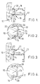
- Fig. 1 is a cross-sectional view of a building component according to the present invention with fastening means in an open position;
- Fig. 2 is a cross-sectional view of an enlarged detail of the building component shown in Fig. 1;
- Fig. 3 is a cross-sectional view of the building component with the fastening; means in a closed position;
- Fig. 4 is a cross-sectional view of an enlarged detail of the building component shown in Fig. 3;
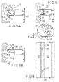
- Figs. 5A and 5B are cross-sectional views of a building component showing respectively two types of thermal breaks provided in one structural member of the building component;
- Fig. 6 is a cross-sectional view of a modified building component;
- Fig. 7 is a cross-sectional view of an enlarged detail of the building component shown in Fig. 6; and
- Fig. 8 is a plan view of a length of a building component as shown in Fig. 5.
-
- Referring to the drawings, a building component comprises an inner
structural member 10 of non-temperature conducting material and an outerstructural member 12 of metallic material. Eachstructural member part 14 of the inner structural member is a tenon, and thepart 16 on the outerstructural member 12 is aformation 18 providing a mortise for location of the corresponding tenon. Theformation 18 is of channel shape having splayed apartlimbs 20 on the inner surface of each of which means for preventing subsequent relative movement between the members is provided, the means being a plurality ofsharp protuberances 22 which project from the limbs. With the tenon located in the mortise the twolimbs 20 are brought together from a splayed attitude to a substantially parallel attitude against the tenon and in which theprotuberances 22 of eachlimb 20 engage and bite into the opposing surfaces of the corresponding tenon. At the translation between thelimbs 20 and aweb 24 of the mortise, a groove 26 is provided to assist in the movement of thelimbs 20. In Figs. 5A and 5B, theouter member 12 is shown provided with athermal break 30. In Fig. 5 A, the break is formed of two ties and in Fig. 5B the break is formed as a block. The ties and block are formed from synthetic plastics material. - In a first modification, as the movement of each
limb 20 of a formation pressed against a corresponding tenon side is or is being completed, atongue 28 is punched out of thelimb 20 into the tenon side as a means of securing against longitudinal movement of one member relative to the other. Thistongue 28 is additional to theprotuberances 22 in the movement prevention means or indeed can be an alternative to the protuberances. - In a second modification, only one protuberance can be provided on the limbs, the shape of which differs as required.
- In a third modification, the movement prevention means may simply be an adhesive bond between the members. This may be additional to one or other of the means described above.
- In use, a building component as described is used to form a window frame to be installed with the metal outer structural members outermost. The advantages of the present invention are the combination of the good weathering characteristics of aluminium and the non-temperature conductivity of wood or plastic material on the interior of the frame.
- Variations and other modifications can be made without departing from the scope of the invention described above and as claimed hereinafter.
Claims (10)
- A method of forming a building component comprising providing an inner structural member of non-temperature conducting material and an outer structural member of metallic material, providing each structural member with one part of a two part fastening, the part of the inner member being a tenon, and the part on the outer member being a formation providing a mortise for location of the corresponding tenon, the formation being of channel shape having splayed apart limbs, bringing the two members together with the tenon located in the mortise, causing the limbs to be moved from a splayed attitude to a substantially parallel attitude against the tenon, and providing means to prevent subsequent movement between the members.
- A method as claimed in Claim 1, wherein the movement prevention means includes providing on the inner surface of each limb one or more sharp protuberances which project therefrom, and which protuberances of each limb engage and bite into the opposing surfaces of the corresponding tenon when the limbs are moved.
- A method as claimed in Claim 1 or 2, wherein as the movement of each limb of a formation being pressed against a corresponding tenon side is or is being completed, a tongue is punched out of the limb into the tenon side.
- A method as claimed in Claim 1, wherein the movement prevention means is a tongue punched out of each limb of a formation into the respective tenon side as it is or is being pressed against the tenon side.
- A method as claimed in Claim 1, wherein the movement prevention means is an adhesive bond between the members.
- A building component comprising an inner structural member and an outer structural member, each structural member having one part of a two part fastening, the part on the inner member being a tenon, and the part on the outer member being a formation providing a mortise for location of the corresponding tenon, the formation being of channel shape having splayed apart limbs which are movable from a splayed attitude to a substantially parallel attitude against the side of the tenon, and means to prevent subsequent movement between the members.
- A building component as claimed in Claim 6, wherein the movement preventing means includes one or more sharp protuberances projecting from the inner surface of each limb and the protuberances of each limb engaging and biting into the opposing surfaces of the tenon when the limbs are moved.
- A building component as claimed in Claim 6 or 7, wherein a tongue is punched out of the or each limb into a respective tenon side as the movement of the limbs is or is being completed.
- A building component as claimed in Claim 6, wherein the movement preventing means comprises a tongue punched out of the or each limb into a respective tenon side as the movement of the limbs is or is being completed.
- A building component as claimed in Claim 6, wherein the movement preventing means comprises an adhesive bond between the members.
Priority Applications (1)
| Application Number | Priority Date | Filing Date | Title |
|---|---|---|---|
| EP00650164A EP1199434A1 (en) | 2000-10-20 | 2000-10-20 | A method of forming a building component from different materials |
Applications Claiming Priority (1)
| Application Number | Priority Date | Filing Date | Title |
|---|---|---|---|
| EP00650164A EP1199434A1 (en) | 2000-10-20 | 2000-10-20 | A method of forming a building component from different materials |
Publications (1)
| Publication Number | Publication Date |
|---|---|
| EP1199434A1 true EP1199434A1 (en) | 2002-04-24 |
Family
ID=8174476
Family Applications (1)
| Application Number | Title | Priority Date | Filing Date |
|---|---|---|---|
| EP00650164A Withdrawn EP1199434A1 (en) | 2000-10-20 | 2000-10-20 | A method of forming a building component from different materials |
Country Status (1)
| Country | Link |
|---|---|
| EP (1) | EP1199434A1 (en) |
Cited By (1)
| Publication number | Priority date | Publication date | Assignee | Title |
|---|---|---|---|---|
| EP3354835A1 (en) * | 2017-01-27 | 2018-08-01 | SCHÜCO International KG | Composite profile |
Citations (4)
| Publication number | Priority date | Publication date | Assignee | Title |
|---|---|---|---|---|
| US3517472A (en) * | 1967-05-08 | 1970-06-30 | Anchor Enterprises Corp | Structural element with thermal barrier means |
| US4982530A (en) * | 1988-10-14 | 1991-01-08 | Sne Enterprises, Inc. | Extruded core sections for wood fenestration mounting frames and sashes |
| US5469683A (en) * | 1994-02-09 | 1995-11-28 | Kawneer Company, Inc. | Thermally insulating composite frame member with snap-in thermal isolator |
| GB2350642A (en) * | 1999-06-04 | 2000-12-06 | Michael John Watson | Two-part building component with mortise and tenon connection |
-
2000
- 2000-10-20 EP EP00650164A patent/EP1199434A1/en not_active Withdrawn
Patent Citations (4)
| Publication number | Priority date | Publication date | Assignee | Title |
|---|---|---|---|---|
| US3517472A (en) * | 1967-05-08 | 1970-06-30 | Anchor Enterprises Corp | Structural element with thermal barrier means |
| US4982530A (en) * | 1988-10-14 | 1991-01-08 | Sne Enterprises, Inc. | Extruded core sections for wood fenestration mounting frames and sashes |
| US5469683A (en) * | 1994-02-09 | 1995-11-28 | Kawneer Company, Inc. | Thermally insulating composite frame member with snap-in thermal isolator |
| GB2350642A (en) * | 1999-06-04 | 2000-12-06 | Michael John Watson | Two-part building component with mortise and tenon connection |
Cited By (1)
| Publication number | Priority date | Publication date | Assignee | Title |
|---|---|---|---|---|
| EP3354835A1 (en) * | 2017-01-27 | 2018-08-01 | SCHÜCO International KG | Composite profile |
Similar Documents
| Publication | Publication Date | Title |
|---|---|---|
| US3028938A (en) | Locked joint and reinforcing construction for fragile sheet material | |
| US4947597A (en) | Window mounting assembly | |
| EP0398937B1 (en) | Protective lath making a plaster joint when plastering a wall | |
| US20080216424A1 (en) | Window joining system | |
| CA2180209C (en) | Structural connecting and sealing member | |
| US20100107524A1 (en) | Sealing spline connector | |
| ATE395481T1 (en) | DEVICE CONSISTS OF TWO BUILDING PLATES THAT CAN BE CONNECTED TO EACH OTHER AND AN INSERT FOR LOCKING THESE BUILDING PLATES | |
| CA2298963A1 (en) | Fence section | |
| EP1285143A1 (en) | Shaped bar for establishing a junction between a structural member and a building surface | |
| US20020170252A1 (en) | Extruded composite interlocking corner assembly | |
| US11131139B2 (en) | End cap arrangements for composite door assembly | |
| EP0318045A1 (en) | Protective fillet for the application of plaster | |
| ATE19423T1 (en) | COMPOSITE PROFILE, PARTICULARLY FOR FRAMES OF WINDOWS, DOORS AND FAÇADE ELEMENTS. | |
| US20160340964A1 (en) | Closure member and the method of making the same | |
| EP1199434A1 (en) | A method of forming a building component from different materials | |
| GB2350642A (en) | Two-part building component with mortise and tenon connection | |
| ATE275233T1 (en) | COMPOSITE PROFILE FOR WINDOWS, FACADES, DOORS OR LIGHT ROOFS | |
| US20070011961A1 (en) | Connector for sash window frame members | |
| PL357072A1 (en) | Plastic window | |
| FR2799228B1 (en) | SYSTEM FOR COVERING STRUCTURAL ELEMENTS OF BUILDING JOINERY | |
| FI83254B (en) | VAERMEISOLERANDE LAMELLPROFIL OCH FOERFARANDE FOER DESS TILLVERKNING. | |
| US6467219B1 (en) | Shutter rail to stile joint | |
| KR200241616Y1 (en) | A Member for Door-Frame | |
| HU9701615D0 (en) | Casement frame for doors, windows, facades or the likes of these | |
| KR200324248Y1 (en) | A assembly of windows and doors |
Legal Events
| Date | Code | Title | Description |
|---|---|---|---|
| PUAI | Public reference made under article 153(3) epc to a published international application that has entered the european phase |
Free format text: ORIGINAL CODE: 0009012 |
|
| AK | Designated contracting states |
Kind code of ref document: A1 Designated state(s): AT BE CH CY DE DK ES FI FR GB GR IE IT LI LU MC NL PT SE Kind code of ref document: A1 Designated state(s): AT BE CH CY DE DK ES FI FR GR IE IT LI LU MC NL PT SE |
|
| AX | Request for extension of the european patent |
Free format text: AL;LT;LV;MK;RO;SI |
|
| 17P | Request for examination filed |
Effective date: 20021023 |
|
| AKX | Designation fees paid |
Free format text: AT BE CH CY DE DK ES FI FR GR IE IT LI LU MC NL PT SE |
|
| STAA | Information on the status of an ep patent application or granted ep patent |
Free format text: STATUS: THE APPLICATION IS DEEMED TO BE WITHDRAWN |
|
| 18D | Application deemed to be withdrawn |
Effective date: 20060404 |