EP1200551B1 - Biogasfermenteranlage - Google Patents
Biogasfermenteranlage Download PDFInfo
- Publication number
- EP1200551B1 EP1200551B1 EP97954752A EP97954752A EP1200551B1 EP 1200551 B1 EP1200551 B1 EP 1200551B1 EP 97954752 A EP97954752 A EP 97954752A EP 97954752 A EP97954752 A EP 97954752A EP 1200551 B1 EP1200551 B1 EP 1200551B1
- Authority
- EP
- European Patent Office
- Prior art keywords
- tank
- biofermentation
- signified
- plant according
- rotting
- Prior art date
- Legal status (The legal status is an assumption and is not a legal conclusion. Google has not performed a legal analysis and makes no representation as to the accuracy of the status listed.)
- Expired - Lifetime
Links
- 239000011888 foil Substances 0.000 claims abstract description 39
- 238000010438 heat treatment Methods 0.000 claims abstract description 13
- 210000003608 fece Anatomy 0.000 claims abstract description 11
- 239000010871 livestock manure Substances 0.000 claims abstract description 11
- 239000007788 liquid Substances 0.000 claims description 22
- XLYOFNOQVPJJNP-UHFFFAOYSA-N water Substances O XLYOFNOQVPJJNP-UHFFFAOYSA-N 0.000 claims description 10
- 238000000855 fermentation Methods 0.000 claims description 8
- 230000004151 fermentation Effects 0.000 claims description 8
- 238000004873 anchoring Methods 0.000 claims description 7
- 238000002156 mixing Methods 0.000 claims description 7
- 238000005086 pumping Methods 0.000 claims description 7
- 239000002184 metal Substances 0.000 claims description 6
- 229910000831 Steel Inorganic materials 0.000 claims description 4
- 238000011049 filling Methods 0.000 claims description 4
- 229920003023 plastic Polymers 0.000 claims description 4
- 239000004033 plastic Substances 0.000 claims description 4
- 239000010959 steel Substances 0.000 claims description 4
- 229920001821 foam rubber Polymers 0.000 claims description 2
- 239000000463 material Substances 0.000 claims description 2
- 229920000573 polyethylene Polymers 0.000 claims 8
- 239000002985 plastic film Substances 0.000 claims 5
- 239000002689 soil Substances 0.000 claims 3
- 229920005830 Polyurethane Foam Polymers 0.000 claims 1
- 239000011248 coating agent Substances 0.000 claims 1
- 238000000576 coating method Methods 0.000 claims 1
- 238000007599 discharging Methods 0.000 claims 1
- 239000004753 textile Substances 0.000 claims 1
- 238000005406 washing Methods 0.000 claims 1
- 230000001681 protective effect Effects 0.000 abstract description 50
- 238000000354 decomposition reaction Methods 0.000 abstract 5
- 238000000605 extraction Methods 0.000 abstract 1
- 239000007789 gas Substances 0.000 description 38
- 239000010408 film Substances 0.000 description 33
- 230000006835 compression Effects 0.000 description 9
- 238000007906 compression Methods 0.000 description 9
- 238000010276 construction Methods 0.000 description 7
- 238000013461 design Methods 0.000 description 6
- 239000013039 cover film Substances 0.000 description 5
- 238000009413 insulation Methods 0.000 description 5
- 230000000694 effects Effects 0.000 description 4
- 238000012423 maintenance Methods 0.000 description 4
- 238000004519 manufacturing process Methods 0.000 description 4
- 238000003756 stirring Methods 0.000 description 4
- 238000007688 edging Methods 0.000 description 3
- 230000002349 favourable effect Effects 0.000 description 3
- 238000009434 installation Methods 0.000 description 3
- 238000000034 method Methods 0.000 description 3
- 239000007787 solid Substances 0.000 description 3
- UFHFLCQGNIYNRP-UHFFFAOYSA-N Hydrogen Chemical compound [H][H] UFHFLCQGNIYNRP-UHFFFAOYSA-N 0.000 description 2
- 230000000035 biogenic effect Effects 0.000 description 2
- 230000015572 biosynthetic process Effects 0.000 description 2
- JJWKPURADFRFRB-UHFFFAOYSA-N carbonyl sulfide Chemical compound O=C=S JJWKPURADFRFRB-UHFFFAOYSA-N 0.000 description 2
- 238000005253 cladding Methods 0.000 description 2
- 230000008878 coupling Effects 0.000 description 2
- 238000010168 coupling process Methods 0.000 description 2
- 238000005859 coupling reaction Methods 0.000 description 2
- 238000005338 heat storage Methods 0.000 description 2
- 229910052739 hydrogen Inorganic materials 0.000 description 2
- 239000001257 hydrogen Substances 0.000 description 2
- 238000000926 separation method Methods 0.000 description 2
- 150000003464 sulfur compounds Chemical class 0.000 description 2
- 238000012546 transfer Methods 0.000 description 2
- 239000002699 waste material Substances 0.000 description 2
- 241000894006 Bacteria Species 0.000 description 1
- 238000013019 agitation Methods 0.000 description 1
- 238000007664 blowing Methods 0.000 description 1
- 238000004040 coloring Methods 0.000 description 1
- 238000005260 corrosion Methods 0.000 description 1
- 230000007797 corrosion Effects 0.000 description 1
- 238000006477 desulfuration reaction Methods 0.000 description 1
- 230000023556 desulfurization Effects 0.000 description 1
- 238000011161 development Methods 0.000 description 1
- 230000029087 digestion Effects 0.000 description 1
- 238000001035 drying Methods 0.000 description 1
- 239000004744 fabric Substances 0.000 description 1
- 239000004615 ingredient Substances 0.000 description 1
- 229910052500 inorganic mineral Inorganic materials 0.000 description 1
- 239000012774 insulation material Substances 0.000 description 1
- 230000000813 microbial effect Effects 0.000 description 1
- 244000005700 microbiome Species 0.000 description 1
- 239000011707 mineral Substances 0.000 description 1
- 239000005416 organic matter Substances 0.000 description 1
- 239000010815 organic waste Substances 0.000 description 1
- 239000002984 plastic foam Substances 0.000 description 1
- 238000012545 processing Methods 0.000 description 1
- 230000005855 radiation Effects 0.000 description 1
- 230000001105 regulatory effect Effects 0.000 description 1
- 230000002787 reinforcement Effects 0.000 description 1
- 238000007789 sealing Methods 0.000 description 1
- 239000002002 slurry Substances 0.000 description 1
- 239000011343 solid material Substances 0.000 description 1
- 229910001220 stainless steel Inorganic materials 0.000 description 1
- 239000010935 stainless steel Substances 0.000 description 1
- 239000000126 substance Substances 0.000 description 1
- 239000002918 waste heat Substances 0.000 description 1
Images



Classifications
-
- C—CHEMISTRY; METALLURGY
- C02—TREATMENT OF WATER, WASTE WATER, SEWAGE, OR SLUDGE
- C02F—TREATMENT OF WATER, WASTE WATER, SEWAGE, OR SLUDGE
- C02F11/00—Treatment of sludge; Devices therefor
- C02F11/02—Biological treatment
- C02F11/04—Anaerobic treatment; Production of methane by such processes
-
- C—CHEMISTRY; METALLURGY
- C12—BIOCHEMISTRY; BEER; SPIRITS; WINE; VINEGAR; MICROBIOLOGY; ENZYMOLOGY; MUTATION OR GENETIC ENGINEERING
- C12M—APPARATUS FOR ENZYMOLOGY OR MICROBIOLOGY; APPARATUS FOR CULTURING MICROORGANISMS FOR PRODUCING BIOMASS, FOR GROWING CELLS OR FOR OBTAINING FERMENTATION OR METABOLIC PRODUCTS, i.e. BIOREACTORS OR FERMENTERS
- C12M21/00—Bioreactors or fermenters specially adapted for specific uses
- C12M21/04—Bioreactors or fermenters specially adapted for specific uses for producing gas, e.g. biogas
-
- C—CHEMISTRY; METALLURGY
- C12—BIOCHEMISTRY; BEER; SPIRITS; WINE; VINEGAR; MICROBIOLOGY; ENZYMOLOGY; MUTATION OR GENETIC ENGINEERING
- C12M—APPARATUS FOR ENZYMOLOGY OR MICROBIOLOGY; APPARATUS FOR CULTURING MICROORGANISMS FOR PRODUCING BIOMASS, FOR GROWING CELLS OR FOR OBTAINING FERMENTATION OR METABOLIC PRODUCTS, i.e. BIOREACTORS OR FERMENTERS
- C12M23/00—Constructional details, e.g. recesses, hinges
-
- C—CHEMISTRY; METALLURGY
- C12—BIOCHEMISTRY; BEER; SPIRITS; WINE; VINEGAR; MICROBIOLOGY; ENZYMOLOGY; MUTATION OR GENETIC ENGINEERING
- C12M—APPARATUS FOR ENZYMOLOGY OR MICROBIOLOGY; APPARATUS FOR CULTURING MICROORGANISMS FOR PRODUCING BIOMASS, FOR GROWING CELLS OR FOR OBTAINING FERMENTATION OR METABOLIC PRODUCTS, i.e. BIOREACTORS OR FERMENTERS
- C12M23/00—Constructional details, e.g. recesses, hinges
- C12M23/02—Form or structure of the vessel
- C12M23/18—Open ponds; Greenhouse type or underground installations
-
- C—CHEMISTRY; METALLURGY
- C12—BIOCHEMISTRY; BEER; SPIRITS; WINE; VINEGAR; MICROBIOLOGY; ENZYMOLOGY; MUTATION OR GENETIC ENGINEERING
- C12M—APPARATUS FOR ENZYMOLOGY OR MICROBIOLOGY; APPARATUS FOR CULTURING MICROORGANISMS FOR PRODUCING BIOMASS, FOR GROWING CELLS OR FOR OBTAINING FERMENTATION OR METABOLIC PRODUCTS, i.e. BIOREACTORS OR FERMENTERS
- C12M27/00—Means for mixing, agitating or circulating fluids in the vessel
- C12M27/02—Stirrer or mobile mixing elements
- C12M27/06—Stirrer or mobile mixing elements with horizontal or inclined stirrer shaft or axis
-
- C—CHEMISTRY; METALLURGY
- C12—BIOCHEMISTRY; BEER; SPIRITS; WINE; VINEGAR; MICROBIOLOGY; ENZYMOLOGY; MUTATION OR GENETIC ENGINEERING
- C12M—APPARATUS FOR ENZYMOLOGY OR MICROBIOLOGY; APPARATUS FOR CULTURING MICROORGANISMS FOR PRODUCING BIOMASS, FOR GROWING CELLS OR FOR OBTAINING FERMENTATION OR METABOLIC PRODUCTS, i.e. BIOREACTORS OR FERMENTERS
- C12M29/00—Means for introduction, extraction or recirculation of materials, e.g. pumps
- C12M29/18—External loop; Means for reintroduction of fermented biomass or liquid percolate
-
- C—CHEMISTRY; METALLURGY
- C12—BIOCHEMISTRY; BEER; SPIRITS; WINE; VINEGAR; MICROBIOLOGY; ENZYMOLOGY; MUTATION OR GENETIC ENGINEERING
- C12M—APPARATUS FOR ENZYMOLOGY OR MICROBIOLOGY; APPARATUS FOR CULTURING MICROORGANISMS FOR PRODUCING BIOMASS, FOR GROWING CELLS OR FOR OBTAINING FERMENTATION OR METABOLIC PRODUCTS, i.e. BIOREACTORS OR FERMENTERS
- C12M41/00—Means for regulation, monitoring, measurement or control, e.g. flow regulation
- C12M41/12—Means for regulation, monitoring, measurement or control, e.g. flow regulation of temperature
- C12M41/18—Heat exchange systems, e.g. heat jackets or outer envelopes
- C12M41/22—Heat exchange systems, e.g. heat jackets or outer envelopes in contact with the bioreactor walls
-
- Y—GENERAL TAGGING OF NEW TECHNOLOGICAL DEVELOPMENTS; GENERAL TAGGING OF CROSS-SECTIONAL TECHNOLOGIES SPANNING OVER SEVERAL SECTIONS OF THE IPC; TECHNICAL SUBJECTS COVERED BY FORMER USPC CROSS-REFERENCE ART COLLECTIONS [XRACs] AND DIGESTS
- Y02—TECHNOLOGIES OR APPLICATIONS FOR MITIGATION OR ADAPTATION AGAINST CLIMATE CHANGE
- Y02E—REDUCTION OF GREENHOUSE GAS [GHG] EMISSIONS, RELATED TO ENERGY GENERATION, TRANSMISSION OR DISTRIBUTION
- Y02E50/00—Technologies for the production of fuel of non-fossil origin
- Y02E50/30—Fuel from waste, e.g. synthetic alcohol or diesel
-
- Y—GENERAL TAGGING OF NEW TECHNOLOGICAL DEVELOPMENTS; GENERAL TAGGING OF CROSS-SECTIONAL TECHNOLOGIES SPANNING OVER SEVERAL SECTIONS OF THE IPC; TECHNICAL SUBJECTS COVERED BY FORMER USPC CROSS-REFERENCE ART COLLECTIONS [XRACs] AND DIGESTS
- Y02—TECHNOLOGIES OR APPLICATIONS FOR MITIGATION OR ADAPTATION AGAINST CLIMATE CHANGE
- Y02W—CLIMATE CHANGE MITIGATION TECHNOLOGIES RELATED TO WASTEWATER TREATMENT OR WASTE MANAGEMENT
- Y02W10/00—Technologies for wastewater treatment
- Y02W10/20—Sludge processing
Definitions
- the invention relates to a biogas fermenter system at least one digester for a digestion Liquid, in particular manure, with the characteristics of The preamble of claim 1.
- digesters are often in the Inlaid floor and with a container film for sealing provided, the container with a black colored Foil, e.g. made of PE or the like, for collecting the biogas is covered.
- the digester is then one Protection from a very tear-resistant film against weather influences covered as used for greenhouses becomes.
- the object of the invention is to have a bio fermenter system to create a septic tank in which both the tank as well as the gas container and the protective cover with one very simple structure can be made and at filling and emptying the liquid and treatment of the biogas possible with little construction and maintenance is with the simplest possible structure of the system.
- the also conical or pyramidal structure of the Protective cover and the foil gas container is through use a support column very simplified, with compliance a steep elevation angle while also being favorable Volume / (surface ratio is possible.
- pyramid angle as an elevation angle for Protective cover and foil gas container results in energetic particularly favorable conditions for the drying effect of Foil gas container on the withdrawn biogas. This is done inside the pyramid-shaped protective cover, inside of the foil gas container an energetic charge of the gas under the influence of the concentrated cosmic rays which compresses the molecular structure of the gas and to leads to an increase in the calorific value of the biogas.
- the cosmic effect Radiation field positive on the microbial implementation processes in the liquid to be digested, through which the Hydrogen content in biogas increases and the calorific value thereby increasing.
- an agitator in the digester becomes special determined by its size and it can either be just one Side agitator or just a central agitator or both be provided.
- the side agitator is advantageously on rollers Rails movable and with a train in different Liquid depths of the digester can be moved to increase the stirring effect optimally set for a good mixing can.
- the central agitator can comprise one or more agitators which are height-adjustable and whose agitating tools work in a horizontal or slightly inclined direction.
- the agitator can also be equipped with a tubular rotor Support column supported all round, be formed.
- the Installation of a thermal cover at a distance above the liquid surface is also advantageous due to the simultaneous the removal of moisture from the surface of the liquid is reduced because of the gas circulation in it Part of the gas container is significantly reduced.
- the supporting function and the Separate insulation function of this cover at least the heat-insulating part made of prefabricated components can be made, which is very easy to install is.
- This thermal cover rests on the outside of the container wall and is attached to the inside of the support column.
- the attachment of the thermal cover to the support column can advantageously on a connecting flange happen the lower and upper part of the support column separates.
- the developed biogas is either left on through openings the flag of the connecting flange or between the components pass through the thermal cover, causing the Construction effort is kept low.
- Fastening the films of the container wall of the gas container and the protective cover is preferably made with a single one Clamp connection on the top or on the outside of the Edge of the digester made, one Clamp the foil in place with a screw clamped on the edge.
- openings with a small cross section can be made, for example, plastic grid strips or the like. Such openings can be produced in a similar manner for the passage of the biogas upwards into the foil gas container through the thermal cover.
- the clamp connection is designed particularly gently if a soft, resistant insert, e.g. made of foam rubber or plastic foam or the like, is inserted, around which the Foil is passed around.
- a soft, resistant insert e.g. made of foam rubber or plastic foam or the like
- Edge edging for the clamping connection of the foils in particular be designed gently.
- the attachment of a work platform above the foil gas container in the area of the top of the protective cover is advantageous because a machine for thermal power coupling or a heater can be installed there that processes the biogas directly and because the attachment of a heat storage device eg for hot water, above the work platform, in the top of the pyramid-shaped or tapered top protective cover, short lines result and is structurally advantageous.
- the dissipation of this stored heat is advantageously carried out either along the support column downwards and through a manhole outwards or outwards along the protective cover.
- the stored and especially enriched in the foil gas container and dried, biogas passes through openings in the Support column, above the connecting flange in one in this attached wash column over that with material for separation the water and, if necessary, for the separation of converted sulfur compounds is filled, and passes from upper end of the support column directly into the line to Thermal power coupling machine or to one installed there Boiler or in a line for the removal of the biogas after Outside. This makes it a very simple, space-saving Treatment of the biogas enables.
- the gas container film is advantageously on the support column attached gastight with a clamp connection, while the Protective cover film on the outside of the work platform is attached.
- the upper part of the protective cover to the top of it consists of a solid material, such as sheet metal, because the one on the work platform under the protective cover installed installations easier to maintain and maintain can be.
- the protective cover film is turned down by several Guy ropes are kept simple and reliable Construction of anchoring trays installed in the floor, e.g. in Form of bored piles, are braced.
- a digester with the protective cover and described The foil gas container is also suitable for other biogenic ones Waste as manure, e.g. also crushed solid organic Waste, to process.
- a bio-fermenter system has a digester 1 of a protective cover 2 is covered, under which a foil gas container 3 spans the digester 1.
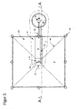
- the digester 1 is formed by a container wall 4, the one spread out in a floor recess, Floor fleece is laid, the digester 1 one down to taper square or pyramidal has a conical structure, with an inclination angle of 27 45 °.
- a discharge tube 13 ends the ground 22 in a pump chamber designed as a shaft 20 and is connected to a pump 30 of a pump system.
- a feed pipe 26 for the manure to be processed leads from the pump 30 over the upper edge 6 into the digester 1 and at a distance from the concrete foundation 5 on profile supports 25 held down on the container wall 4 until close to the bottom 8 thereof ,
- the feed pipe 26 is fastened in the concrete foundation 5 by means of anchoring screw connections which are passed through the container wall 4 in a sealed manner.
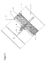
- the container wall 4 consists of a bottom film 14 on the an insulation layer 15 made of a common insulation material is applied and in the lower part of the Container wall 4 covered with an applied heating register 16 on which a container film 17 is placed Seals the container wall to the inside of the digester 1.
- a side agitator 28 is arranged in the digester 1 movable with rollers on an agitator guide 31 from rails is, which is passed through sealed to the container wall 4 Anchor screw connections 24, the profile beams 25 wear is attached, the side agitator 28 with a train, not shown, such as a winch, the Height can be moved in the digester 1 and with the stirring tool 32 is arranged to work in a horizontal direction.
- a thermal cover 33 which from a load-bearing part 34 on which a heat-insulating part 35 is assembled from prefabricated components.
- the heat-insulating part 35 is covered by a lower protective film 56 and an upper protective film 56 '. which are attached to the support column 11 and to the border 7.
- the heat-insulating part 35 is pulled up on the support column 11 with a tubular piece.
- the thermal cover 33 lies on the inside of the connecting flange 49 and rests on the outside of the container wall 4.
- thermoelectric Thermal power plant 46 there are 51 in the upper part the support column 11 openings through which the biogas from the foil gas container 3 into one in the support column 11 located, wash column 50 can enter and in the Wash filling 52 of water and other undesirable ingredients is freed, after which it is at the upper end 18 of the support column 11 through a feed line into the thermoelectric Thermal power plant 46 occurs.
- the upper edge 6 of the digester 1 is located approximately the bottom surface 21 and has a border 7, on the bottom film 14 and the container film 17 of the container wall 4, and the gas container film 23 'of the film gas container 3 and the cover sheet 23 of the protective cover 2 attached are.
- the support column 11 carries on its upper 18 a working platform 43 on the outer edge of which the black-colored cover film 23 is fastened, while the gas container film 23 'is attached gas-tight on the inside of the support column 11.
- the working platform 43 is covered up to the top 44 of the pyramid-shaped protective cover 2 with its upper part 54, which is provided with a fixed covering.
- thermoelectric thermal power plant 46 At the tip 44 is a heat accumulator 45 for the heat the thermoelectric thermal power plant 46 attached, the with feed and discharge lines 47, 47 'for the heat transfer medium connected to the outside of the protective cover 2 are brought down.
- the protective cover 2 is with its guy 48 on several Anchors 53, which are designed as bored piles, held and has a manhole in the area of the concrete foundation 5 57, to which the foil gas container 3 is also gas-tight connected.
- the bottom film 14 is the Container wall 4 on the inside of a steel profile Edge surround 7 with a compression fitting 37, consisting from a clamping plate 41 and a screw 40, held down fixed after giving a compliant Insert 39 ', e.g. a plastic tube that is led around.
- the cover sheet 23 is the protective cover 2 on the outside of the steel profile of the border 7 with a compression fitting 38 attached.
- the container film 17 of the container wall 4 is together with the Gas container film 23 'around a flat, flexible insert 39 led around and with a clamping plate 41 of a compression fitting 36 sealed down, with screw connections 40 is attached.
- openings of small cross-section e.g. through interim deposits made of plastic grids or the like.
Landscapes
- Health & Medical Sciences (AREA)
- Chemical & Material Sciences (AREA)
- Life Sciences & Earth Sciences (AREA)
- Engineering & Computer Science (AREA)
- Organic Chemistry (AREA)
- Zoology (AREA)
- Bioinformatics & Cheminformatics (AREA)
- Wood Science & Technology (AREA)
- Genetics & Genomics (AREA)
- General Health & Medical Sciences (AREA)
- Biomedical Technology (AREA)
- Biochemistry (AREA)
- General Engineering & Computer Science (AREA)
- Biotechnology (AREA)
- Sustainable Development (AREA)
- Microbiology (AREA)
- Molecular Biology (AREA)
- Environmental & Geological Engineering (AREA)
- Oil, Petroleum & Natural Gas (AREA)
- Clinical Laboratory Science (AREA)
- General Chemical & Material Sciences (AREA)
- Physics & Mathematics (AREA)
- Analytical Chemistry (AREA)
- Thermal Sciences (AREA)
- Chemical Kinetics & Catalysis (AREA)
- Hydrology & Water Resources (AREA)
- Water Supply & Treatment (AREA)
- Treatment Of Sludge (AREA)
- Micro-Organisms Or Cultivation Processes Thereof (AREA)
- Apparatus Associated With Microorganisms And Enzymes (AREA)
- Processing Of Solid Wastes (AREA)
- Preparation Of Compounds By Using Micro-Organisms (AREA)
- Agricultural Chemicals And Associated Chemicals (AREA)
Description
Es ist auch möglich, ein Mittelrührwerk in ein, in die Tragsäule eingebautes, Zwischenstück einzusetzen, wobei der Motor im Zwischenstück angebracht ist und die Rührwerkzeuge, insbesonders waagrecht nach außen gerichtet, in axialer Richtung, vorzugsweise nach oben arbeitend, umlaufen.
Für den Durchtritt des Biogases nach oben in den Foliengasbehälter durch die thermische Abdeckung hindurch können solche Öffnungen in ähnlicher Weise hergestellt werden.
Zum Ausgleich der Volumsänderungen des Foliengasbehälters ist es von Vorteil, wenn am oberen Ende der Schutzabdeckung, z.B. an der Arbeitsplattform, eine Ausgleichsöffnung im bereich zwischen der Abdeckfolie der Schutzabdeckung und der Gaspehälterfolie angebracht ist und zur Sicherung letzterer eine Ausblasleitung mit Abfackelung, mit einem Überdruckventil von etwa 1 bis 2 mbar vorgesehen ist.
Es zeigt:
- Fig. 1
- einen Biogasfermenter in Seitenansicht, geschnitten;
- Fig. 2
- eine Draufsicht auf den Biogasfermenter nach Fig. 1, mit teilweise aufgerissener Abdeckung;
- Fig. 3
- einen Ausschnitt aus der Behälterwand des Faulbehälters;
- Fig. 4
- den oberen Rand des Faulbehälters mit einer Randeinfassung aus Metallprofil mit Klemmverbindungen für Folien, im Schnitt;
- Fig. 5
- den oberen Rand des Faulbehälters mit einer Randeinfassung aus Betonprofil, mit innen liegender Klemmverbindung für die Folien, im Schnitt;
- Fig. 6
- den oberen Rand des Faulbehälters mit einer Randeinfassung aus Betonprofil, mit einer an der Oberseite angeordneten Klemmverbindung für die Folien, im Schnitt.
Das Einspeisungsrohr 26 ist dabei im Betonfundament 5 mit durch die Behälterwand 4 abgedichtet hindurchgeführten Verankerungsverschraubungen befestigt.
Die thermische Abdeckung 33 liegt innen auf dem Verbindungsflansch 49 auf und ruht außen auf der Behälterwand 4.
Die Arbeitsplattform 43 ist nach oben zu bis zur Spitze 44 der pyramidenförmigen Schutzabdeckung 2 mit derem oberen, mit einer festen Verkleidung versehenen, Teil 54 abgedeckt.
- 1
- Faulbehälter
- 2
- Schutzabdeckung
- 3
- Foliengasbehälter
- 4
- Behälterwand des Faulbehälters 1
- 5
- Betonfundament am Faulbehälter 1
- 6
- oberer Rand des Faulbehälters 1
- 7
- Randeinfassung des Faulbehälters 1
- 8
- Boden des Faulbehälters 1
- 9
- Bodenplatte des Faulbehälters 1
- 10
- Austragsschacht des Faulbehälters 1
- 11
- Tragsäule für die Schutzabdeckung 2 und den Foliengasbehälter 3
- 12
- Verankerungsplatte der Tragsäule 11
- 13
- Austragsrohr des Faulbehälters 1
- 14
- Bodenfolie der Behälterwand 4 des Faulbehälters 1
- 15
- Isolationsschicht der Behälterwand 4
- 16
- Heizregister der Behälterwand 4
- 17
- Behälterfolie der Behälterwand 4
- 18
- oberes Ende der Tragsäule 11
- 19
- unteres Ende der Tragsäule 11
- 20
- Pumpenkammer
- 21
- Bodenoberfläche
- 22
- Erdboden
- 23
- Abdeckfolie der Schutzabdeckung 2
- 23'
- Gasbehälterfolie
- 24
- Verankerungsverschraubung für das Einspeisungsrohr 26
- 25
- Profilträger
- 26
- Einspeisungsrohr für die Gülle
- 27
- Neigungswinkel der Behälterwand 4
- 28
- Seitenrührwerk
- 29,29'
- Mittelrührwerk
- 30
- Pumpe der Pumpanlage
- 31
- Rührwerksführung
- 32,32'
- Rührwerkszeuge
- 33
- thermische Abdeckung des Faulbehälters 1
- 34
- tragender Teil der thermischen Abdeckung 33
- 35
- wärmedämmender Teil der thermischen Abdeckung 33
- 36
- Klemmverschraubung für die Behälterfolie 17 und die Folie des Foliengasbehälters 3
- 37
- Klemmverschraubung für die Bodenfolie 14 der Behälterwand 4
- 38
- Klemmverschraubung für die Abdeckfolie 23 der Schutzabdeckung 2
- 39,39'
- nachgiebige Einlage der Klemmverschraubung 36,37,38
- 40
- Verschraubung der Klemmverschraubung 36,37,38
- 41,41'
- Klemmplatte der Klemmverschraubung, 36,37,38
- 42
- Kantenschiene der Randeinfassung 7
- 43
- Arbeitsplattform der Tragsäule 11
- 44
- Spitze der Schutzabdeckung 2
- 45
- Wärmespeicher
- 46
- thermoelektrische Wärmekraftanlage
- 47,47'
- Zu- und Ableitung für das Wärmeübertragungsmittel
- 48
- Abspannung der Schutzabdeckung 22
- 49
- Verbindungsflansch der Tragsäule 11
- 50
- Waschsäule in der Tragsäule 11
- 51
- oberer Teil der Tragsäule 11
- 52
- Waschfüllung der Waschsäule 50
- 53
- Verankerung der Abspannung 48
- 54
- oberer Teil der Schutzabdeckung 2
- 55
- Erhebungswinkel der Schutzabdeckung 2
- 56
- obere Schutzfolie des wärmedämmenden Teils 35 der thermischen Abdeckung 33
- 56'
- untere Schutzfolie des wärmedämmenden Teils 35 der thermischen Abdeckung 33
- 57
- Mannloch in der Schutzabdeckung 2 und in dem Foliengasbehälter 3
Claims (31)
- Biofermenteranlage mit wenigstens einem Faulbehälter für eine auszufaulende Flüssigkeit, insbesondere Gülle, mit einer dachförmigen, abgestützten Schutzabdeckung, innerhalb der ein gasdichter Foliengasbehälter den Faulbehälter, zu diesem hin offen, überdeckt und mit einem Einspeisungs- und einem Austragsrchr und einer Pumpanlage für die Gülle, mit einer Heizungseinrichtung und wenigstens einem Rührwerk im Faulbehälter ausgestattet und mit wenigstens einer Abführungsleitung für einen Energieträger versehen ist, dadurch gekennzeichnet, daß eine, insbesonders als Rohr oder Profilrohr ausgebildete Tragsäule (11) mittig im Faulbehälter (1) angeordnet ist, an deren oberen Ende (18) die äußere Schutzabdeckung (2) befestigt und das obere Ende des Foliengasbehälters(3) gasdicht angebracht ist und die mit dem unteren Ende (19) im Faulbehälter (1), insbesonders auf dem Boden (8) desselben, verankert ist, daß der Faulbehälter (1) kegelig oder quadratisch pyramidenförmig, vom oberen Rand (6) nach unten zu, insbesonders von der Höhe der Bodenoberfläche (21) ausgehend, sich verjüngend geformt ist und seine Behälterwand (4) im wesentlichen von einer Bodenfolie (14), die auf einem Bodenvlies, vorzugsweise unmittelbar, auf dem Erdboden (22) aufgelegt ist und einer die Innenwand bildenden Behälterfolie (17) gebildet ist, wobei der Neigungswinkel (27) der Behälterwand (4) zur Waagrechten zwischen 30° und 50° und vorzugsweise etwa 35° bis 45° beträgt und daß die Schutzabdeckung (2) des Faulbehälters (1) kegelig oder quadratisch pyramidenförmig, nach oben zu, insbesonders von der Höhe des Erdbodens, vom oberen Rand (6) des Faulbehälters (1) ausgehend, sich verjüngend geformt ist, wobei der Erhebungswinkel (55) zwischen 40° und 60°, vorzugsweise mehr als 45° beträgt.
- Biofermenteranlage nach Anspruch 1, dadurch gekennzeichnet, daß die Schutzabdeckung (2) des Faulbehälters (1) einen Erhebungswinkel (55) von zwischen 50° und 55° und vorzugsweise von etwa 51° bis 52° aufweist.
- Biofermenteranlage nach Anspruch 1 oder 2, dadurch gekennzeichnet, daß die Schutzabdeckung (2) des Faulbehälters (1) einen Erhebungswinkel (55) von im wesentlichen 51,87°, dem Neigungswinkel der "Großen Pyramide" entsprechend aufweist und einen nach unten sich verjüngenden, quadratisch pyramidenförmigen Faulbehälter (1) mit einem Neigungswinkel (27) von mehr als 30° und vorzugsweise wenigstens 45° überdeckt.
- Biofermenteranlage nach Anspruch 1 oder 3, dadurch gekenneichnet, daß die Behälterwand (4) des Faulbehälters (1) von einer Bodenfolie (14) gebildet ist, auf der eine Isolationsschicht (15), insbesonders aus PU-Schaum, durchgehend aufgebracht ist, auf der, wenigstens über einen Teil der Behälterwand (4), vorzugsweise einem unteren Teil derselben, Heizungsregister (16) einer Heizungseinrichtung, insbesonders als Warmwasser-Rohrregister, aufgelegt sind und als Innenwand eine aufliegende Behälterfolie (17) dichtend aufgebracht ist.
- Biofermenteranlage nach Anspruch 1, 3 oder 4, dadurch gekennzeichnet, daß wenigstens an einer Stelle des Faulbehälters (1), bei einem quadratischen Umriß des Faulbehälters (1), vorzugsweise in der Mitte einer Seite desselben, ein vom oberen Rand (6) des Faulbehälters (1) nach unten bis zu dessen Boden (8) verlaufend ein Betonfundament (5) oder dergl. eingebaut ist und mit einer ebenen Bodenplatte (9), insbesonders in einem vertieften Abzugsschacht (10) angeordnet, abschließt, auf der die Tragsäule (11) mit einer Verankerungsplatte (12) oder dergl. befestigt ist.
- Biofermenteranlage nach Anspruch 1, oder 5, dadurch gekennzeichnet, daß das Einspeisungsrohr (26) vom oberen Rand (6) des Faulbehälters (1) her, im wesentlichen bis an den Boden (8) oder zumindest in den Bodenbereich desselben reicht und, vorzugsweise im Abstand (5) von der Behälterwand (4), insbesonders auf in das Bodenfundament (5) eingesetzten, durch die Behälterwand (4) abgedichtet hindurchgeführte Ankerverschraubungen (24) über Befestigungsprofile (25) befestigt ist und mit einer Pumpe (39) einer Pumpanlage in der, vorzugsweise als Pumpenschacht ausgebildeten Pumpenkammer (20) verbunden ist und das Austragsrohr (13) in der ebenen Bodenplatte (9), insbesonders in einem vertieften Abzugsschacht (10) angeordnet, mündet und vorzugsweise an der Behälterwand (4) entlang nach oben über den oberen Rand (6) des Faulbehälters (1) oder unterhalb desselben im Erdboden in eine Pumpenkammer (20) geleitet ist.
- Biofermenteranlage nach Anspruch 1, 5 oder 6 dadurch gekennzeichnet, daß das Austragsrohr (13) gleichzeitig als Einspeisungsrohr vorgesehen ist.
- Biofermenteranlage nach Anspruch 1 bis 7, dadurch gekennzeichnet, daß der obere Rand (6) des Faulbehälters (1) mit einer Randeinfassung (7) aus einem Betonprofil, versehen ist, an der die Bodenfolie (14) und die Behälterfolie (17) der Behälterwand (4) und die Abdeckfolie (23) der Schutzabdeckung (2) und die Gasbehälterfolie (23') des Foliengasbehälters (3), vorzugsweise von außen her, dichtend befestigt sind.
- Biofermenteranlage nach Anspruch 1 bis 7, dadurch gekennzeichnet, daß der obere Rand (6) des Faulbehälters (1) mit einer Randeinfassung (7) aus einem Profil, insbesonders aus Edelstahl oder dergl., versehen ist, das vorzugsweise aus einem nach innen offenen U-Profil besteht.
- Biofermenteranlage nach einem der Ansprüche 1 bis 9, dadurch gekennzeichnet, daß wenigstens ein Seitenrührwerk (28) an der Behälterwand (4), insbesonders auf dem Betonfundament (5), von oben, unmittelbar unterhalb des oberen Randes (6) des Faulbehälters (1), bis nach unten, nahezu an dessen Boden (8), vorzugsweise mit Rollen auf einer Rührwerksführung (31), in Form von Bahnen, verfahrbar ist, die an durch die Behälterwand (4) abgedichtet hindurchgeführte Ankerverschraubunzen (24) über Befestigungsprofile (25) befestigt ist und motorisch angetrieben von einem Zugwerk, vorzugsweise von einer am oberen Rand (6) des Faulbehälters (1) insbesonders außerhalb der Schutzabdeckung (2), aufgestellten Seilwinde bewegbar ist.
- Biofermenteranlage nach einem der Ansprüche 1 bis 10, dadurch gekennzeichnet, daß an der Tragsäule (11) wenigstens ein Mittelrührwerk (29) angeordnet und an einer Rührwerksführung (31), insbesonders mit im wesentlichen radial zur Tragsäule und waagrecht arbeitend ausgerichteten Rührwerkswerkzeugen (32), angeordnet sind und daß bei zwei Mittelrührwerken (29,29') diese in der Ausrichtung der Rührwerkswerkzeuge (32,32') zur Achse der Tragsäule (11) beiderseits versetzt angeordnet sind oder daß die Ausrichtung der Rührwerkswerkzeuge teilweise oder vollständig tangential zur Achse der Tragsäule (11) vorgesehen ist.
- Biofermenteranlage nach einem der Ansprüche 1 bis 11, dadurch gekennzeichnet, daß in der Tragsäule (11), insbesondere zwischen Flanschen, ein zentrales Mittelrührwerk eingebaut ist, das insbesonders rohrförmig ausgebildet ist und dessen Rührwerkzeuge vorzugsweise im wesentlichen waagrecht ausgerichtet, in axialer Richtung insbesonders nach oben gerichtet arbeitend angeordnet sind, deren Antriebsmotor vorzugsweise axial zwischen die Flansche der Tragsäule (11) eingesetzt ist.
- Biofermenteranlage nach einem der Ansprüche 1 bis 12, dadurch gekennzeichnet, daß die Tragsäule (11) direkt oder über ein in dieser geführtes Zuführungsrohr, das mit einer Umwälzpumpe der Pumpanlage verbunden ist, für die Umwälzung der Gülle vorgesehen ist, die im Bereich des oberen Randes (6), insbesonders in einem Abstand oberhalb des höchsten Standes der Flüssigkeitsoberfläche im Faulbehälter (1) durch wenigstens eine Öffnung, vorzugweise im wesentlichen waagrecht oder flach nach unten gerichtet, ausbringbar ist.
- Biofermenteranlace nach Anspruch 13, dadurch gekennzeichnet, daß mehrere Öffnungen, vorzugsweise mit Düsen, insbesonders unterschiedlicher Strahlweite und mit einer Räumvorrichtung vor dem Einlauf der Öffnungen ausgestattet, vorgesehen sind.
- Biofermenteranlage nach einem der Ansprüche 1 bis 14, dadurch gekennzeichnet, daß der Faulbehälter (1) am oberen Rand (6) mit einer thermischen Abdeckung (33) versehen ist, die an diesem und an der Tragsäule (11) befestigt ist und vorzugsweise im Abstand oberhalb des höchsten Standes der Gülleoberfläche im Faulbehälter (1) angebracht ist und insbesonders aus einem tragenden Teil (34) und einem darauf aufgelegten wärmedämmenden Teil (35) besteht und vorzugsweise der wärmedämmende Teil (35) aus vorgefertigten Bauelementen aufgebaut ist, die insbesonders mit Nut und Feder zusammengefügt sind und daß an der Tragsäule zusätzlich ein wärmedämmendes Rohrelement (36) auf die thermische Abdeckung (33) aufgesetzt ist.
- Biofermenteranlage nach Anspruch 15, dadurch gekennzeichnet, daß jedes vorgefertigte Bauelement des wärmedämmenden Teiles (35) der thermischen Abdeckung (33) mit einer Schutzfolie (56,56') umhüllt ist oder daß mehrere oder alle vorgefertigten Bauelemente mit einer oberen Schutzfolie (56) und mit einer unteren Schutzfolie (56') abgedeckt sind, die beide an der Randeinfassung (7) und an der Tragsäule (11) befestigt sind.
- Biofermenteranlage nach einem der Ansprüche 1 bis 16, dadurch gekennzeichnet, daß die thermische Abdeckung (33) mit dem tragenden Teil (34) und dem darauf verlegten oder verbundenen wärmedämmendem Teil (35) am oberen Rand (6) des Faulbehälters (1) auf der Behälterwand (4) aufliegend angeordnet ist.
- Biofermenteranlage nach einem der Ansprüche 1 bi 17, dadurch gekennzeichnet, daß zumindest die Bodenfolie (14) und die Behälterfolie (17) der Behälterwand (4) die Gasbehälterfolie (23') des Foliengasbehälters (3) und die Abdeckfolie (23) der Schutzabdeckung (2) mit einer einzigen gasdichten Klemmverschraubung (36) zusammengefaßt befestigt sind, wobei die Klemmverschraubung (36) aus einer Verschraubung (40), die vorzugsweise an der Oberseite oder der Außenseite des Profils, insbesonders des Betonprofils, der Randeinfassung (7) eingeschraubt ist und aus einer Klemmplatte (41) besteht.
- Biofermenteranlage nach Anspruch 1 oder 18, dadurch gekennzeichnet, daß zwischen der Abdeckfolie (23) und der. Gasbehälterfolie (23'), insbesonders nach außen führende, Durchtrittsöffnungen geringen Querschnittes, vorzugsweise durch eine Zwischenlage hergestellt, angebracht sind, derart daß Kondenswasser austreten kann.
- Biofermenteranlage nach Anspruch 1 oder 18, dadurch gekennzeichnet, daß zwischen den vorgefertigten Bauelementen des wärmedämmenden Teiles (35) der thermischen Abdeckung (33) oder deren einhüllenden Schutzfolien und vorzugsweise am Verbindungsflansch (49), Durchtrittsöffnungen zum Foliengasbehälter (3) hin angebracht sind.
- Biofermenteranlage nach einem der Ansprüche 1 bis 20, dadurch gekennzeichnet, daß die Bodenfolie (14) und die Behälterfolie (17) der Behälterwand (4) die Gasbehälterfolie (23' ) des Foliengasbehälters (3) und die Abdeckfolie (23) der Schutzabdeckung (2) mit mehreren gasdichten Klemmverschraubungen (36, 37, 38) an der Randeinfassung (7) des Faulbehälters (1) festgelegt sind.
- Biofermenteranlage nach Anspruch 1 bis 21, dadurch gekennzeichnet, daß die Behälterfolie (17) und die Gasbehälterfolie (23') des Foliengasbehälters (3) gemeinsam um eine nachgiebige Einlage (39), insbesonders einer Platte aus Schaumgummi oder dergl., herumgeführt und vorzugsweise außen auf dem oberen Schenkel eines U-Profils der Randeinfassung (7) mit einer von einer Verschraubung (40) niedergehaltenen Klemmplatte (41) der Klemmverschraubung (36) gemeinsam befestigt sind.
- Biofermenteranlage nach einem der Ansprüche 1 bis 22, dadurch gekennzeichnet, daß die Abdeckfolie (23) außen und die Bodenfolie (14) innen am U-Profil der Randeinfassung (7) jeweils um eine nachgiebige Einlage (39'), vorzugsweise aus einem Plastikschlauch oder dergl. bestehend, herumgeführt und mit einer von einer Verschraubung (40) niedergehaltenen Klemmplatte (41'), jeweils einzeln, befestigt sind.
- Biofermenteranlage nach einem der Ansprüche 1 bis 23, dadurch gekennzeichnet, daß bei Ausbildung der Randeinfassung (7) als Betonprofil die Verschraubung (40) der Klemmverschraubung (36) mit einer Verankerung im Beton gehalten ist und die Kante des Betonprofils der Randeinfassung (7) mit einer im Beton verankerten Kantenschiene (42) als Dichtungsauflage versehen ist.
- Biofermenteranlage nach einem der Ansprüche 1 bis 24, dadurch gekennzeichnet, daß die Folien, insbesonders die Abdeckfolie (23) und die Folie des Foliengeasbehälters (3) dunkel, lichtundurchlässig, eingefärbt und vorzugsweise mit Gewebeeinlagen verstärkt sind und daß die Bodenfolie (14) und die Behälterfolie (17) der Behälterwand (4) in der Art und Qualität von Teichfolien ausgebildet sind.
- Biofermenteranlage nach einem der Ansprüche 1 bis 25, dadurch gekennzeichnet, daß die Tragsäule (11) am oberen Ende mit einer Arbeitsplattform (43) versehen ist, die einen ähnlichen Umriß wie der Faulbehälter (1) aufweist und an deren Umfang die Abdeckfolie (23) der Schutzabdeckung (2) insbesonders mit einer Klemmverbindung, befestigt ist und daß die Gasbehälterfolie (23') des Fcliengasbehälters (3) gasdicht am oberen Ende der Tragsäule (11) gasdicht festgehalten ist.
- Biofermenteranlage nach einem der Ansprüche 1 bis 26, dadurch gekennzeichnet, daß, insbesonders zur Arbeitsplattform (43) hin, im oberen Bereich zwischen der Abdeckfolie (23) der Schutzabdeckung (2) und der Gasbehälterfolie (23') eine Ausgleichsöffnung vorgesehen ist.
- Biofermenteranlage nach einem der Ansprüche 1 bis 27, dadurch gekennzeichnet, daß die Arbeitsplattform (43) vom oberen Teil (54) der Schutzabdeckung (2), insbesonders aus einem festen Material wie Blech oder dergl., überdeckt ist, in die ein Wärmespeicher (45) insbesonders ein Warmwasserspeicher für eine thermoelektrische Wärmekraftanlage (46) oder für ein Heizgerät, insbesonders einem Warmwasserheizkessel, vorzugsweise an deren Spitze (44) eingebaut ist, wobei die Zu- und Ableitungen (47,47') für das Wärmeübertragungsmittel und/oder die elektrischen Leitungen eines Generators und/oder eine Gasableitung innen an der Tragsäule (11) nach unten und oberhalb der thermischen Abdeckung (33) an die Randeinfassung (7) des Faulbehälters (1) und vorzugsweise durch ein dort angeordnetes Mannloch (57) abgedichtet nach außen geführt oder außen an der Schutzabdeckung (2), insbesonders an einer Abspannung (48) herab, geführt sind.
- Biofermenteranlage nach einem der Ansprüche 1 bis 28, dadurch gekennzeichnet, daß die Tragsäule (11) oberhalb des höchsten Standes der Gülle im Faulbehälter (1) mit einem Verbindungsflansch (49) abgeteilt ist, oberhalb von dem, vorzugsweise oberhalb der thermischen Abdeckung (33), wenigstens eine Öffnung oder eine Zuleitung, die vom oberen Ende des Foliengasbehälters (3) herabgeführt ist, für den Eintritt des Biogases angebracht ist, die in eine Waschsäule (50) mit einer Waschfüllung (52) führt, die im oberen Teil der Tragsäule (11) direkt oder indirekt eingebaut ist und am oberen Ende der Tragsäule (11) mit der Zuleitung zu der Wärmekraftanlage (46) oder dem Heizgerät oder einer Gasableitung verbunden ist.
- Biofermenteranlage nach einem der Ansprüche 1 bis 29, dadurch gekennzeichnet, daß die Abspannung (48) der Schutzabdeckung (2) an der Erdoberfläche an im Boden angebrachten Verankerungen (53), die insbesonders als Bohrpfähle ausgebildet sind, befestigt ist, die an mehreren Umfangsstellen des Faulbehälters (1) und bei quadratischem Querschnitt desselben, insbesonders an dessen Ecken (54), angebracht sind.
- Biofermenteranlage nach einem der Ansprüche 1 bis 30, dadurch gekennzeichnet, daß bei einer Biofermenteranlage wenigstens zwei Faulbehälter (1) mit Schutzabdeckung (2) und Foliengasbehälter (3) vorgesehen sind, die jeweils abwechselnd mit auszufaulender Flüssigkeit befüllt, ausgefault und entleert werden, wobei die Entleerung in einen weiteren, größeren Nachfaulbehälter mit Schutzabdeckung und Foliengasbehälter erfolgt, mit einem Faulraumvolumen, das dem der beiden Faulbehälter (1) zusammen, insbesonders in etwa entspricht, und aus dem die Flüssigkeit nach dem Ausfaulen abgepumpt wird.
Applications Claiming Priority (2)
| Application Number | Priority Date | Filing Date | Title |
|---|---|---|---|
| AT0223696A AT407523B (de) | 1996-12-20 | 1996-12-20 | Biogasfermenteranlage |
| PCT/EP1997/007271 WO1998028402A1 (de) | 1996-12-20 | 1997-12-23 | Biogasfermenteranlage |
Publications (2)
| Publication Number | Publication Date |
|---|---|
| EP1200551A1 EP1200551A1 (de) | 2002-05-02 |
| EP1200551B1 true EP1200551B1 (de) | 2003-11-05 |
Family
ID=3530555
Family Applications (1)
| Application Number | Title | Priority Date | Filing Date |
|---|---|---|---|
| EP97954752A Expired - Lifetime EP1200551B1 (de) | 1996-12-20 | 1997-12-23 | Biogasfermenteranlage |
Country Status (8)
| Country | Link |
|---|---|
| EP (1) | EP1200551B1 (de) |
| AT (2) | AT407523B (de) |
| AU (1) | AU5985498A (de) |
| DE (2) | DE29780436U1 (de) |
| DK (1) | DK1200551T3 (de) |
| ES (1) | ES2210597T3 (de) |
| PT (1) | PT1200551E (de) |
| WO (1) | WO1998028402A1 (de) |
Cited By (2)
| Publication number | Priority date | Publication date | Assignee | Title |
|---|---|---|---|---|
| EP2062965A1 (de) | 2007-11-26 | 2009-05-27 | AGROTEL GmbH | Behälterabdeckung mit Gasmembran |
| CN108841579A (zh) * | 2018-07-03 | 2018-11-20 | 湖北鼎誉环保科技有限公司 | 一种处理农村有机垃圾的玻璃钢沼气池 |
Families Citing this family (15)
| Publication number | Priority date | Publication date | Assignee | Title |
|---|---|---|---|---|
| DE10052373A1 (de) * | 2000-10-20 | 2002-05-02 | Envitec Mall Umweltsysteme Gmb | Biofermenter |
| DE10104460A1 (de) * | 2001-02-01 | 2002-08-22 | Farmatic Biotech Energy Ag | Biogasfermenter mit integriertem Gasspeicher als Einkomponenten-Bauteil |
| EP1704221B1 (de) * | 2003-07-17 | 2010-03-10 | Gerhard Hermann | Biogasfermentationsanlage |
| DE10354598B4 (de) * | 2003-11-21 | 2007-04-05 | Eisenmann Maschinenbau Gmbh & Co. Kg | Fermentierbehälter |
| DE102006035227B3 (de) * | 2006-07-26 | 2007-09-06 | Mt-Energie Gmbh & Co. Kg | Behälter, insbesondere Biogasfermenter |
| AT505174B1 (de) * | 2007-04-20 | 2009-02-15 | Sattler Ag | Gasspeicher |
| AT507028B1 (de) * | 2008-06-25 | 2012-07-15 | Sattler Ag | Erdbeckenfermenter |
| WO2013039407A1 (en) | 2011-09-16 | 2013-03-21 | Green Gas As | Modular anaerobic digestion system |
| CN102851204B (zh) * | 2012-09-10 | 2014-10-29 | 罗晓晖 | 夹联软片盖幕式垃圾沼化系统 |
| DE202014011246U1 (de) * | 2014-03-13 | 2018-10-18 | Ökobit Gmbh | Vorrichtung zum Vergären von Biomasse zum Erzeugen von Gas |
| DE202014103688U1 (de) * | 2014-08-08 | 2015-11-11 | JOPE Beteiligungs GmbH | Biomassespeicher |
| FR3043396B1 (fr) | 2015-11-05 | 2021-01-01 | Adg Ateliers Des Graves | Module de couverture, dispositif et systeme de methanisation |
| NL2021116B1 (en) | 2018-06-13 | 2019-12-19 | Biobrella Bv | A method of generating biogas, and a column |
| FR3083219B1 (fr) | 2018-06-28 | 2020-05-29 | Adg - Ateliers Des Graves | Module de couverture collecteur d’eau pour cuve de methanisation |
| FR3108120B1 (fr) | 2020-03-12 | 2022-07-15 | Adg Ateliers Des Graves | Module de couverture, dispositif et système de méthanisation |
Family Cites Families (11)
| Publication number | Priority date | Publication date | Assignee | Title |
|---|---|---|---|---|
| CH531670A (de) * | 1971-02-24 | 1972-12-15 | Mueller Ag Klingnau E | Druckbegrenzer an einem Gas enthaltenden Behälter |
| US4184892A (en) * | 1975-07-11 | 1980-01-22 | Jay Anderson | Organic digester apparatus and method |
| CH648348A5 (de) * | 1980-07-11 | 1985-03-15 | Frossard Pierre | Vorrichtung und verfahren zur anaeroben vergaerung organischer feststoffe zum zwecke der gewinnung eines brennbaren gases. |
| NL8004293A (nl) * | 1980-07-25 | 1982-02-16 | Oostwouder Bv | Houder voor de opslag van gas onder lage druk. |
| EP0106857B1 (de) * | 1982-04-22 | 1986-09-17 | Biowatt AG | Flexible abdeckung für einen gasspeicher |
| US4579654A (en) * | 1982-06-25 | 1986-04-01 | Corite Investments Ltd. | Apparatus for the anaerobic fermentation of organic waste material such as liquid manure |
| US4437987A (en) * | 1982-07-01 | 1984-03-20 | Thornton Marvin L | Anaerobic digester gas collection and storage systems |
| CH662339A5 (de) * | 1984-11-20 | 1987-09-30 | Sulzer Ag | Reaktionsgefaess. |
| ATE81669T1 (de) * | 1987-03-02 | 1992-11-15 | Christoph Frese | Verfahren und anlage zur herstellung von biogas aus dickfluessigen vergaerbaren medien. |
| EP0521302A3 (en) * | 1991-05-31 | 1993-03-17 | Herrmannsdorfer Entwicklungsgesellschaft Fuer Agrar- Und Umwelttechnik Gmbh & Co., Kg | Cover for an upwardly open container, eg. a slurry pit for the production of biogas, a gas sealed shaft passage and an agitator therefor |
| DE19608996C1 (de) * | 1996-03-08 | 1997-04-10 | Karl Weitz | Vorrichtung zur Lagerung flüssiger organischer Stoffe wie Gülle und Speicherung von Biogas |
-
1996
- 1996-12-20 AT AT0223696A patent/AT407523B/de not_active IP Right Cessation
-
1997
- 1997-12-23 DE DE29780436U patent/DE29780436U1/de not_active Expired - Lifetime
- 1997-12-23 WO PCT/EP1997/007271 patent/WO1998028402A1/de not_active Ceased
- 1997-12-23 AU AU59854/98A patent/AU5985498A/en not_active Abandoned
- 1997-12-23 AT AT97954752T patent/ATE253630T1/de not_active IP Right Cessation
- 1997-12-23 PT PT97954752T patent/PT1200551E/pt unknown
- 1997-12-23 EP EP97954752A patent/EP1200551B1/de not_active Expired - Lifetime
- 1997-12-23 ES ES97954752T patent/ES2210597T3/es not_active Expired - Lifetime
- 1997-12-23 DK DK97954752T patent/DK1200551T3/da active
- 1997-12-23 DE DE59710972T patent/DE59710972D1/de not_active Expired - Fee Related
Cited By (3)
| Publication number | Priority date | Publication date | Assignee | Title |
|---|---|---|---|---|
| EP2062965A1 (de) | 2007-11-26 | 2009-05-27 | AGROTEL GmbH | Behälterabdeckung mit Gasmembran |
| DE102007057118A1 (de) | 2007-11-26 | 2009-05-28 | Agrotel Gmbh | Behälterabdeckung mit Gasmembran |
| CN108841579A (zh) * | 2018-07-03 | 2018-11-20 | 湖北鼎誉环保科技有限公司 | 一种处理农村有机垃圾的玻璃钢沼气池 |
Also Published As
| Publication number | Publication date |
|---|---|
| DE29780436U1 (de) | 2000-10-05 |
| ATA223696A (de) | 2000-08-15 |
| WO1998028402A1 (de) | 1998-07-02 |
| AT407523B (de) | 2001-04-25 |
| PT1200551E (pt) | 2004-03-31 |
| AU5985498A (en) | 1998-07-17 |
| ATE253630T1 (de) | 2003-11-15 |
| EP1200551A1 (de) | 2002-05-02 |
| DE59710972D1 (de) | 2003-12-11 |
| DK1200551T3 (da) | 2004-03-08 |
| ES2210597T3 (es) | 2004-07-01 |
Similar Documents
| Publication | Publication Date | Title |
|---|---|---|
| EP1200551B1 (de) | Biogasfermenteranlage | |
| EP2878365B1 (de) | Rührwerk für einen Biogasfermenter | |
| DE102008038262B4 (de) | Verfahren und Vorrichtung zur Vergärung von Biomasse | |
| AT507028B1 (de) | Erdbeckenfermenter | |
| DE2535756A1 (de) | Behaelter mit vorrichtungen zur erzeugung von methangas und aus organischen abfaellen | |
| DE2944584A1 (de) | Vorrichtung und verfahren zur herstellung von biogas | |
| DE19756485C2 (de) | Faulbehälter mit Rührwerk und Verfahren zum Betreiben eines Rührwerks in einem Faulbehälter | |
| EP1992683A1 (de) | Biogasanlage zur Herstellung von Biogas in einem einstufigen Durchflussverfahren | |
| EP2166081A2 (de) | Biogasanlage mit einem Fermenterbehälter | |
| EP2092051B1 (de) | Fermenter | |
| WO2008128631A2 (de) | Biogasanlage zur herstellung von biogas in einem einstufigen durchflussverfahren | |
| DE102010053242A1 (de) | Faulbehälter zur Erzeugung von Biogas | |
| DE3411264A1 (de) | Verfahren und vorrichtung zur erzeugung von biogas | |
| DE2943962A1 (de) | Verfahren zur herstellung von festduenger durch trennung von guelle und vorrichtung zur durchfuehrung dieses verfahren | |
| DE102008038065A1 (de) | Biogasanlagen-Fermenter | |
| DE2821796B2 (de) | Faultank für die anaerobe Gärung | |
| DE3737870A1 (de) | Verfahren und anlage zur herstellung von biogas aus dickfluessigen vergaerbaren medien | |
| EP1704221B1 (de) | Biogasfermentationsanlage | |
| DE19805580C1 (de) | Biogasfermenter | |
| EP2034007A2 (de) | Mittel zum Heizen eines liegenden, rohrförmigen Fermenters | |
| DE20121357U1 (de) | Vorrichtung zum Gären organischer Substanzen | |
| EP0280762B1 (de) | Verfahren und Anlage zur Herstellung von Biogas aus dickflüssigen vergärbaren Medien | |
| CH657150A5 (en) | Biogas reactor | |
| WO2015090261A1 (de) | Baukastensystem zur erstellung eines biogasfermenters | |
| DE10240286A1 (de) | Anlage sowie Verfahren zur Herstellung von Biogas |
Legal Events
| Date | Code | Title | Description |
|---|---|---|---|
| PUAI | Public reference made under article 153(3) epc to a published international application that has entered the european phase |
Free format text: ORIGINAL CODE: 0009012 |
|
| 17P | Request for examination filed |
Effective date: 20000928 |
|
| AK | Designated contracting states |
Kind code of ref document: A1 Designated state(s): AT BE CH DE DK ES FI FR GB GR IE IT LI NL PT SE |
|
| GRAH | Despatch of communication of intention to grant a patent |
Free format text: ORIGINAL CODE: EPIDOS IGRA |
|
| GRAH | Despatch of communication of intention to grant a patent |
Free format text: ORIGINAL CODE: EPIDOS IGRA |
|
| RAP1 | Party data changed (applicant data changed or rights of an application transferred) |
Owner name: HANEL, MICHAEL Owner name: HERMANN, GERHARD |
|
| RIN1 | Information on inventor provided before grant (corrected) |
Inventor name: HERMANN, GERHARD |
|
| RIN1 | Information on inventor provided before grant (corrected) |
Inventor name: HERMANN, GERHARD |
|
| GRAA | (expected) grant |
Free format text: ORIGINAL CODE: 0009210 |
|
| AK | Designated contracting states |
Kind code of ref document: B1 Designated state(s): AT BE CH DE DK ES FI FR GB GR IE IT LI NL PT SE |
|
| PG25 | Lapsed in a contracting state [announced via postgrant information from national office to epo] |
Ref country code: FI Free format text: LAPSE BECAUSE OF FAILURE TO SUBMIT A TRANSLATION OF THE DESCRIPTION OR TO PAY THE FEE WITHIN THE PRESCRIBED TIME-LIMIT Effective date: 20031105 |
|
| REG | Reference to a national code |
Ref country code: GB Ref legal event code: FG4D Free format text: NOT ENGLISH |
|
| REG | Reference to a national code |
Ref country code: CH Ref legal event code: EP |
|
| REF | Corresponds to: |
Ref document number: 59710972 Country of ref document: DE Date of ref document: 20031211 Kind code of ref document: P |
|
| REG | Reference to a national code |
Ref country code: IE Ref legal event code: FG4D Free format text: GERMAN |
|
| PGFP | Annual fee paid to national office [announced via postgrant information from national office to epo] |
Ref country code: ES Payment date: 20040116 Year of fee payment: 7 |
|
| PGFP | Annual fee paid to national office [announced via postgrant information from national office to epo] |
Ref country code: IE Payment date: 20040119 Year of fee payment: 7 |
|
| PGFP | Annual fee paid to national office [announced via postgrant information from national office to epo] |
Ref country code: SE Payment date: 20040123 Year of fee payment: 7 Ref country code: GR Payment date: 20040123 Year of fee payment: 7 |
|
| PGFP | Annual fee paid to national office [announced via postgrant information from national office to epo] |
Ref country code: NL Payment date: 20040128 Year of fee payment: 7 |
|
| PGFP | Annual fee paid to national office [announced via postgrant information from national office to epo] |
Ref country code: BE Payment date: 20040204 Year of fee payment: 7 |
|
| PGFP | Annual fee paid to national office [announced via postgrant information from national office to epo] |
Ref country code: DK Payment date: 20040210 Year of fee payment: 7 |
|
| PGFP | Annual fee paid to national office [announced via postgrant information from national office to epo] |
Ref country code: GB Payment date: 20040211 Year of fee payment: 7 |
|
| REG | Reference to a national code |
Ref country code: SE Ref legal event code: TRGR |
|
| REG | Reference to a national code |
Ref country code: CH Ref legal event code: NV Representative=s name: BUECHEL, VON REVY & PARTNER |
|
| REG | Reference to a national code |
Ref country code: DK Ref legal event code: T3 |
|
| GBT | Gb: translation of ep patent filed (gb section 77(6)(a)/1977) |
Effective date: 20040223 |
|
| REG | Reference to a national code |
Ref country code: GR Ref legal event code: EP Ref document number: 20040400454 Country of ref document: GR |
|
| REG | Reference to a national code |
Ref country code: PT Ref legal event code: SC4A Free format text: AVAILABILITY OF NATIONAL TRANSLATION Effective date: 20040205 |
|
| REG | Reference to a national code |
Ref country code: ES Ref legal event code: FG2A Ref document number: 2210597 Country of ref document: ES Kind code of ref document: T3 |
|
| ET | Fr: translation filed | ||
| PLBE | No opposition filed within time limit |
Free format text: ORIGINAL CODE: 0009261 |
|
| STAA | Information on the status of an ep patent application or granted ep patent |
Free format text: STATUS: NO OPPOSITION FILED WITHIN TIME LIMIT |
|
| 26N | No opposition filed |
Effective date: 20040806 |
|
| PG25 | Lapsed in a contracting state [announced via postgrant information from national office to epo] |
Ref country code: IE Free format text: LAPSE BECAUSE OF NON-PAYMENT OF DUE FEES Effective date: 20041223 Ref country code: GB Free format text: LAPSE BECAUSE OF NON-PAYMENT OF DUE FEES Effective date: 20041223 |
|
| PG25 | Lapsed in a contracting state [announced via postgrant information from national office to epo] |
Ref country code: SE Free format text: LAPSE BECAUSE OF NON-PAYMENT OF DUE FEES Effective date: 20041224 Ref country code: ES Free format text: LAPSE BECAUSE OF NON-PAYMENT OF DUE FEES Effective date: 20041224 |
|
| PG25 | Lapsed in a contracting state [announced via postgrant information from national office to epo] |
Ref country code: BE Free format text: LAPSE BECAUSE OF NON-PAYMENT OF DUE FEES Effective date: 20041231 |
|
| PG25 | Lapsed in a contracting state [announced via postgrant information from national office to epo] |
Ref country code: DK Free format text: LAPSE BECAUSE OF NON-PAYMENT OF DUE FEES Effective date: 20050103 |
|
| BERE | Be: lapsed |
Owner name: *HANEL MICHAEL Effective date: 20041231 Owner name: *HERMANN GERHARD Effective date: 20041231 |
|
| PG25 | Lapsed in a contracting state [announced via postgrant information from national office to epo] |
Ref country code: NL Free format text: LAPSE BECAUSE OF NON-PAYMENT OF DUE FEES Effective date: 20050701 |
|
| PG25 | Lapsed in a contracting state [announced via postgrant information from national office to epo] |
Ref country code: GR Free format text: LAPSE BECAUSE OF NON-PAYMENT OF DUE FEES Effective date: 20050704 |
|
| REG | Reference to a national code |
Ref country code: DK Ref legal event code: EBP |
|
| EUG | Se: european patent has lapsed | ||
| GBPC | Gb: european patent ceased through non-payment of renewal fee |
Effective date: 20041223 |
|
| PG25 | Lapsed in a contracting state [announced via postgrant information from national office to epo] |
Ref country code: FR Free format text: LAPSE BECAUSE OF NON-PAYMENT OF DUE FEES Effective date: 20050831 |
|
| NLV4 | Nl: lapsed or anulled due to non-payment of the annual fee |
Effective date: 20050701 |
|
| REG | Reference to a national code |
Ref country code: IE Ref legal event code: MM4A |
|
| PG25 | Lapsed in a contracting state [announced via postgrant information from national office to epo] |
Ref country code: PT Free format text: LAPSE BECAUSE OF NON-PAYMENT OF DUE FEES Effective date: 20050923 |
|
| REG | Reference to a national code |
Ref country code: FR Ref legal event code: ST |
|
| PG25 | Lapsed in a contracting state [announced via postgrant information from national office to epo] |
Ref country code: IT Free format text: LAPSE BECAUSE OF NON-PAYMENT OF DUE FEES;WARNING: LAPSES OF ITALIAN PATENTS WITH EFFECTIVE DATE BEFORE 2007 MAY HAVE OCCURRED AT ANY TIME BEFORE 2007. THE CORRECT EFFECTIVE DATE MAY BE DIFFERENT FROM THE ONE RECORDED. Effective date: 20051223 |
|
| PG25 | Lapsed in a contracting state [announced via postgrant information from national office to epo] |
Ref country code: LI Free format text: LAPSE BECAUSE OF NON-PAYMENT OF DUE FEES Effective date: 20051231 |
|
| REG | Reference to a national code |
Ref country code: ES Ref legal event code: FD2A Effective date: 20041224 |
|
| REG | Reference to a national code |
Ref country code: FR Ref legal event code: D3 |
|
| REG | Reference to a national code |
Ref country code: CH Ref legal event code: PL |
|
| REG | Reference to a national code |
Ref country code: CH Ref legal event code: AEN Free format text: DAS PATENT IST AUFGRUND DES WEITERBEHANDLUNGSANTRAGS VOM 11.10.2006 REAKTIVIERT WORDEN. |
|
| BERE | Be: lapsed |
Owner name: *HANEL MICHAEL Effective date: 20041231 Owner name: *HERMANN GERHARD Effective date: 20041231 |
|
| REG | Reference to a national code |
Ref country code: FR Ref legal event code: ST Effective date: 20071130 |
|
| PG25 | Lapsed in a contracting state [announced via postgrant information from national office to epo] |
Ref country code: PT Free format text: LAPSE BECAUSE OF NON-PAYMENT OF DUE FEES Effective date: 20031223 |
|
| PGFP | Annual fee paid to national office [announced via postgrant information from national office to epo] |
Ref country code: FR Payment date: 20080104 Year of fee payment: 11 |
|
| PGFP | Annual fee paid to national office [announced via postgrant information from national office to epo] |
Ref country code: DE Payment date: 20080625 Year of fee payment: 11 |
|
| REG | Reference to a national code |
Ref country code: CH Ref legal event code: PL Ref country code: CH Ref legal event code: AEN Free format text: REAKTIVIERUNG NACH IRRTUEMLICHER LOESCHUNG |
|
| REG | Reference to a national code |
Ref country code: CH Ref legal event code: PCOW Free format text: HERMANN, GERHARD;AUSTERWALDWEG 1;4210 UNTERWEITERSDORF (AT) $ M. MICHAEL HANEL;WIDENGASSE 39;5070 FRICK (CH) |
|
| PG25 | Lapsed in a contracting state [announced via postgrant information from national office to epo] |
Ref country code: DE Free format text: LAPSE BECAUSE OF NON-PAYMENT OF DUE FEES Effective date: 20090701 |
|
| PGFP | Annual fee paid to national office [announced via postgrant information from national office to epo] |
Ref country code: CH Payment date: 20090630 Year of fee payment: 12 |
|
| REG | Reference to a national code |
Ref country code: CH Ref legal event code: PL |
|
| PGFP | Annual fee paid to national office [announced via postgrant information from national office to epo] |
Ref country code: AT Payment date: 20100630 Year of fee payment: 13 |
|
| PG25 | Lapsed in a contracting state [announced via postgrant information from national office to epo] |
Ref country code: LI Free format text: LAPSE BECAUSE OF NON-PAYMENT OF DUE FEES Effective date: 20091231 Ref country code: CH Free format text: LAPSE BECAUSE OF NON-PAYMENT OF DUE FEES Effective date: 20091231 |
|
| PG25 | Lapsed in a contracting state [announced via postgrant information from national office to epo] |
Ref country code: AT Free format text: LAPSE BECAUSE OF NON-PAYMENT OF DUE FEES Effective date: 20101223 |
|
| PG25 | Lapsed in a contracting state [announced via postgrant information from national office to epo] |
Ref country code: FR Free format text: LAPSE BECAUSE OF NON-PAYMENT OF DUE FEES Effective date: 20061231 |