EP1201364A1 - Gerät zum Festwalzen von Kurbelwellen - Google Patents
Gerät zum Festwalzen von Kurbelwellen Download PDFInfo
- Publication number
- EP1201364A1 EP1201364A1 EP01120063A EP01120063A EP1201364A1 EP 1201364 A1 EP1201364 A1 EP 1201364A1 EP 01120063 A EP01120063 A EP 01120063A EP 01120063 A EP01120063 A EP 01120063A EP 1201364 A1 EP1201364 A1 EP 1201364A1
- Authority
- EP
- European Patent Office
- Prior art keywords
- crankshaft
- connecting rod
- rolling
- additional
- force
- Prior art date
- Legal status (The legal status is an assumption and is not a legal conclusion. Google has not performed a legal analysis and makes no representation as to the accuracy of the status listed.)
- Granted
Links
- 238000005096 rolling process Methods 0.000 title claims description 50
- 238000005452 bending Methods 0.000 claims abstract description 20
- 230000035882 stress Effects 0.000 abstract description 8
- 230000006355 external stress Effects 0.000 abstract description 2
- 230000007704 transition Effects 0.000 description 8
- 239000000463 material Substances 0.000 description 4
- 238000002485 combustion reaction Methods 0.000 description 1
- 230000000694 effects Effects 0.000 description 1
- 238000005259 measurement Methods 0.000 description 1
- 230000036316 preload Effects 0.000 description 1
Images


Classifications
-
- B—PERFORMING OPERATIONS; TRANSPORTING
- B24—GRINDING; POLISHING
- B24B—MACHINES, DEVICES, OR PROCESSES FOR GRINDING OR POLISHING; DRESSING OR CONDITIONING OF ABRADING SURFACES; FEEDING OF GRINDING, POLISHING, OR LAPPING AGENTS
- B24B49/00—Measuring or gauging equipment for controlling the feed movement of the grinding tool or work; Arrangements of indicating or measuring equipment, e.g. for indicating the start of the grinding operation
- B24B49/16—Measuring or gauging equipment for controlling the feed movement of the grinding tool or work; Arrangements of indicating or measuring equipment, e.g. for indicating the start of the grinding operation taking regard of the load
-
- B—PERFORMING OPERATIONS; TRANSPORTING
- B24—GRINDING; POLISHING
- B24B—MACHINES, DEVICES, OR PROCESSES FOR GRINDING OR POLISHING; DRESSING OR CONDITIONING OF ABRADING SURFACES; FEEDING OF GRINDING, POLISHING, OR LAPPING AGENTS
- B24B39/00—Burnishing machines or devices, i.e. requiring pressure members for compacting the surface zone; Accessories therefor
- B24B39/04—Burnishing machines or devices, i.e. requiring pressure members for compacting the surface zone; Accessories therefor designed for working external surfaces of revolution
- B24B39/045—Burnishing machines or devices, i.e. requiring pressure members for compacting the surface zone; Accessories therefor designed for working external surfaces of revolution the working tool being composed of a plurality of working rolls or balls
Definitions
- the invention relates to a device for deep rolling Radii or recesses on main or connecting rod bearings from Crankshafts with the help of deep rolling rollers and support rollers on the respective main or connecting rod bearing to support the applied by the deep rolling rollers to the crankshaft Rolling force.
- crankshafts Force in the direction of that occurring in operation Load is applied to roll down.
- crankshafts made of high-strength Materials can withstand high rolling forces occur that the crankshafts no longer with the normal tools can be rolled without this deep rolling rollers fail after a short time.
- Applying tensile stress during deep rolling the external load would decrease the rolling force allow a similar distribution of the axial Internal stresses as with deep rolling without external load produce.
- the object of the present invention results in that known devices for deep rolling radii or Grooving on main or connecting rod bearings of crankshafts to develop so that the common ones Deep rolling tools have a longer service life or with the usual deep rolling tools in usual Downtimes to roll crankshafts out of one high-strength material.
- the task is accomplished by an application facility an additional external stress in the direction of the load on the crankshaft during operation the deep rolling of the radii or punctures.
- an additional external stress in the direction of the load on the crankshaft during operation the deep rolling of the radii or punctures is accomplished by an application facility an additional external stress in the direction of the load on the crankshaft during operation the deep rolling of the radii or punctures.
- Device from at least one chuck for the Crankshaft, which has a tensile force in the longitudinal direction of the Can apply crankshaft to the crankshaft.
- a particularly simple design of the device is obtained by using the support rollers over which the Deep rolling rollers are supported to apply a additional bending force. That is also next to it Spread the cheeks of the crankshaft with the help of additional spreading rollers possible.
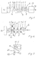
- a Crankshaft 6 considered, such as in a 4 cylinder internal combustion engine used for motor vehicles becomes.
- the crankshaft 6 starts at a flange 7, and ends in a pin 8.
- FIGS. 2 and 3 is about Support rollers 15 an additional load on the crankshaft 6 applied.
- the additional load corresponds to the operating load the crankshaft 6 in the engine (not shown). 2 the crankshaft 6 is in turn in a chuck 10 curious; excited. In the transition area 16 cause deep rolling 17 the deep rolling.
- the deep rolling rollers 17 are supported by support rollers 15 supported. In the present example, the Support rollers 15 with an additional force 18 applied.
- the additional force 24 is one turn Crankshaft 6 changed so that the bending moment 22 of the just rolled the desired amount and has the right sign.
- crankshaft 6 is a lateral via support rollers 48 Force 27 applied to the pin 8 of the crankshaft 6.
- the length of the crankshaft 6 arises within the crankshaft 6, the bending moment 28 from the chuck 10 is added.
- the bending moments 28 in the Crankshaft 6 can also by a more distant Deep rolling device (not shown) or via the tailstock (not shown) or via a bezel (not shown) be generated. Again all bearings 1 to 5 and 1 ' to 4 ', for which the bending moment 28 in amount and Sign has the desired size, be rolled.
- the middle connecting rod bearings 2 'and 3' under additional load be rolled down.
- the additional load is from the two Additional forces 29 and 30 applied, which over their respective support rollers 15 on the connecting rod bearings 2 'and 3' the crankshaft 6 act.
- the deep rolling forces 31 engage each on the main bearing 2, on the connecting rod bearing 2 ', Main bearing 3, on connecting rod bearing 3 'and on main bearing 4.
- the additional forces 29 and 30 generate the additional Bending moment, thus correspond to the piston forces of one Engine at top dead center.
- the three support roller forces 32, 33 and 34 attack the main bearings 2, 3 and 4 and thus correspond to the bearing of the crankshaft 6 in one Engine.
- the support roller forces 32, 33 and 34 hold the Additional forces 29 and 30 the balance.
- the Additional forces 32, 33 and 34 are each over Transfer support rollers 15 to the crankshaft 6.
- crankshaft 6 at risk of breakage can now under the additional load of additional forces 29 and 30 be rolled down.
- the connecting rod bearings 1 'and 4' can be used in this configuration not be rolled because the direction of action of the Deep rolling forces 31 which act on the main bearings 2, 3 and 4 act in the wrong direction. To remedy this the crankshaft 6 shifted and then rotated by 180 °. 8 shows analogously the deep rolling of the two Main bearings 1 and 2 and the connecting rod bearing 1 '. On the Main bearings 1 and 2 act as additional forces 35 and 36, while the additional forces 37 on the connecting rod bearings 1 'and 2' and 38 act. The arrangement of the support rollers 15 is in 8 also indicated.
- crankshaft 6 When deep rolling the front main bearings 4 and 5 and Connecting rod bearings 3 'and 4' engage additional forces 39 and 40 on the main bearings 4 and 5 and the additional forces 41 and 42 on the connecting rod bearings 3 'and 4', the crankshaft 6 is rotated further by 180 °.
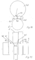
- a pair of expanding rollers 45 is offset in the direction provided, as can be clearly seen in FIG. 11.
- the expanding rollers 45 act in the direction of the arrows 46 the cheeks 16 of the crankshaft 6 and widen the cheeks 16 in the direction of arrows 46.
- the connecting rod bearing 2 ' is applied in the amount of for example 4 t, is created by the expanding rollers 45 an axially expanding force 46 on the order of 6.2 kN. Both tensile residual stresses in the Conrod bearing 2 'and in the crank arms 16 generated.
Landscapes
- Engineering & Computer Science (AREA)
- Mechanical Engineering (AREA)
- Shafts, Cranks, Connecting Bars, And Related Bearings (AREA)
- Rolling Contact Bearings (AREA)
Abstract
Description
- Fig. 1 eine Einrichtung zum Aufbringen einer Zugkraft auf die Kurbelwelle,
- Fig. 2 und Fig. 3 eine Einrichtung zum Aufbringen einer Zusatzlast auf die Kurbelwelle,
- Fig. 4 und Fig. 5 eine Einrichtung zum Aufbringen eines Biegemoments,
- Fig. 6 eine weitere Einrichtung zum Aufbringen eines Biegemoments,
- Fig. 7, Fig. 8 und Fig. 9 jeweils eine Einrichtung zum Aufbringen von Zusatzkräften auf die Kurbelwelle,
- Fig. 10 und Fig. 11 jeweils eine Einrichtung zum Aufweiten der Wangen einer Kurbelwelle.
- 1
- Hauptlager
- 1'
- Pleuellager
- 2
- Hauptlager
- 2'
- Pleuellager
- 3
- Hauptlager
- 3'
- Pleuellager
- 4
- Hauptlager
- 4'
- Hauptlager
- 5
- Hauptlager
- 6
- Kurbelwelle
- 7
- Flansch
- 8
- Zapfen
- 9
- Kurbelwange
- 10
- Spannfutter
- 11
- Spannfutter
- 12
- Spannfutter Kraft in axialer Richtung
- 13
- Übergangsbereich
- 14
- Übergangsbereich
- 15
- Stützrolle
- 16
- Übergangsbereich
- 17
- Festwalzrollen
- 18
- zusätzliche Kraft
- 19
- Druckmittelzylinder
- 20
- Kolbenstange
- 21
- Biegemoment
- 22
- Biegemoment
- 23
- seitliche Kraft
- 24
- seitliche Kraft
- 25
- Festwalzkraft
- 26
- Festwalzkraft
- 27
- seitliche Kraft
- 28
- Biegemoment
- 29
- Zusatzkraft Pleuellager
- 30
- Zusatzkraft Pleuellager
- 31
- Festwalzkräfte
- 32
- Zusatzkraft Hauptlager
- 33
- Zusatzkraft Hauptlager
- 34
- Zusatzkraft Hauptlager
- 35
- Zusatzkraft Hauptlager
- 36
- Zusatzkraft Hauptlager
- 37
- Zusatzkraft Pleuellager
- 38
- Zusatzkraft Pleuellager
- 39
- Zusatzkraft Hauptlager
- 40
- Zusatzkraft Hauptlager
- 41
- Zusatzkraft Pleuellager
- 42
- Zusatzkraft Pleuellager
- 43
- Drehrichtung
- 44
- Versatz
- 45
- Aufweitrolle
- 46
- Aufweitung
- 47
- Stützrollen
- 48
- Stützrollen
Claims (6)
- Gerät zum Festwalzen von Radien oder Einstichen an Haupt- oder Pleuellagern von Kurbelwellen mit Hilfe von Festwalzrollen und Stützrollen am jeweiligen Haupt- oder Pleuellager zum Abstützen der von den Festwalzrollen auf die Kurbelwelle aufgebrachten Walzkraft, gekennzeichnet durch eine Einrichtung (10, 11, 15, 23, 24, 28, 45, 47, 48) zum Aufbringen einer zusätzlichen äusseren Belastung der Kurbelwelle (6) während des Festwalzens der Radien oder Einstiche (13, 14, 16).
- Gerät nach Anspruch1,
dadurch gekennzeichnet, dass die Einrichtung aus wenigstens einem Spannfutter (10, 11) für die Kurbelwelle (6) besteht, welches eine Zugkraft (12) in Längsrichtung der Kurbelwelle (6) auf die Kurbelwelle aufbringt. - Gerät nach Anspruch 1,
dadurch gekennzeichnet, dass die Einrichtung (23, 24, 27) eine Biegemoment (21, 22, 28) auf die Kurbelwelle (6) aufbringt. - Gerät nach Anspruch 3,
dadurch gekennzeichnet, dass die Einrichtung aus einem Spannfutter (10), einem Reitstock oder einer Lünette besteht, zwischen denen die Kurbelwelle (6) eingespannt ist. - Gerät nach Anspruch 3,
dadurch gekennzeichnet, dass die Einrichtung von den Stützrollen (15, 47, 48) gebildet wird, über die eine zusätzliche Biegespannung auf die Kurbelwelle (6) aufgebracht wird. - Gerät nach Anspruch 3,
dadurch gekennzeichnet, dass die Einrichtung aus einem Paar von Spreizrollen (45) besteht.
Applications Claiming Priority (2)
| Application Number | Priority Date | Filing Date | Title |
|---|---|---|---|
| DE10052753 | 2000-10-25 | ||
| DE10052753A DE10052753A1 (de) | 2000-10-25 | 2000-10-25 | Gerät zum Festwalzen von Kurbelwellen |
Publications (2)
| Publication Number | Publication Date |
|---|---|
| EP1201364A1 true EP1201364A1 (de) | 2002-05-02 |
| EP1201364B1 EP1201364B1 (de) | 2007-02-28 |
Family
ID=7660928
Family Applications (1)
| Application Number | Title | Priority Date | Filing Date |
|---|---|---|---|
| EP01120063A Expired - Lifetime EP1201364B1 (de) | 2000-10-25 | 2001-08-21 | Gerät zum Festwalzen von Kurbelwellen |
Country Status (5)
| Country | Link |
|---|---|
| US (1) | US6651474B2 (de) |
| EP (1) | EP1201364B1 (de) |
| JP (1) | JP4243446B2 (de) |
| AT (1) | ATE355154T1 (de) |
| DE (2) | DE10052753A1 (de) |
Cited By (2)
| Publication number | Priority date | Publication date | Assignee | Title |
|---|---|---|---|---|
| CN104302447A (zh) * | 2012-02-16 | 2015-01-21 | 黑根沙伊特-Mfd有限公司及两合公司 | 提高机轴,特别是曲轴的强度的方法和工具 |
| EP3912759A1 (de) * | 2020-05-18 | 2021-11-24 | Dr. Joachim Hug | Verfahren und vorrichtung zur erhöhung einer dauerfestigkeit einer welle |
Families Citing this family (11)
| Publication number | Priority date | Publication date | Assignee | Title |
|---|---|---|---|---|
| EP1342536A1 (de) * | 2002-03-02 | 2003-09-10 | Hegenscheidt-MFD GmbH & Co. KG | Vorrichtung zur drehenden Mitnahme einer Kurbelwelle |
| FR2863921B1 (fr) * | 2003-12-18 | 2007-01-12 | Renault Sas | Outil de galetage |
| DE102004013257B3 (de) * | 2004-03-18 | 2005-08-18 | Hegenscheidt-Mfd Gmbh & Co. Kg | Verfahren zum Erhöhen der Dauerfestigkeit von Kurbelwellen |
| JP4676723B2 (ja) | 2004-07-30 | 2011-04-27 | 富士通株式会社 | キャッシュメモリ、プロセッサ、キャッシュメモリの製造方法、プロセッサの製造方法 |
| US7188497B2 (en) * | 2005-04-07 | 2007-03-13 | International Engine Intellectual Property Company, Llc | Method for straightening an eccentric shaft |
| ATE438048T1 (de) * | 2006-06-23 | 2009-08-15 | Muhr & Bender Kg | Randschichtverbessern von tellerfedern oder wellfedern |
| DE102006029316A1 (de) * | 2006-06-23 | 2007-12-27 | Muhr Und Bender Kg | Festwalzen von Tellerfedern oder Wellfedern |
| WO2010054648A1 (de) | 2008-11-12 | 2010-05-20 | Hegenscheidt-Mfd Gmbh & Co. Kg | Verfahren zum erhöhen der biegefestigkeit von kurbelwellen |
| CN101885131A (zh) * | 2009-05-12 | 2010-11-17 | 南车襄樊机车有限公司 | 曲线轴滚压机 |
| DE102010056616A1 (de) * | 2010-12-23 | 2012-06-28 | Hegenscheidt-Mfd Gmbh & Co. Kg | Verfahren zum Richtwalzen von Kurbelwellen |
| RU2553124C2 (ru) * | 2013-07-19 | 2015-06-10 | Владимир Станиславович Олешко | Способ упрочнения металлических деталей машин |
Citations (4)
| Publication number | Priority date | Publication date | Assignee | Title |
|---|---|---|---|---|
| JPS63127871A (ja) * | 1986-11-17 | 1988-05-31 | Daihatsu Motor Co Ltd | クランクシヤフトの加工方法 |
| US4860566A (en) * | 1987-01-17 | 1989-08-29 | Hans-Georg Augustin | Method and apparatus for straightening a workpiece |
| RU2021098C1 (ru) * | 1991-07-01 | 1994-10-15 | Производственно-коммерческое предприятие "Теко Лтд." | Способ обработки нежестких валов |
| RU2086393C1 (ru) * | 1992-11-14 | 1997-08-10 | Владимир Васильевич Вождаенко | Способ снижения внутренних напряжений в деталях типа валов |
Family Cites Families (6)
| Publication number | Priority date | Publication date | Assignee | Title |
|---|---|---|---|---|
| US3583191A (en) * | 1969-02-13 | 1971-06-08 | Cargill Detroit Corp | Compressive straightener |
| DE3438742A1 (de) * | 1984-10-23 | 1986-04-30 | Maschinenfabrik Alfing Keßler GmbH, 7080 Aalen | Verfahren zur steigerung der dauerfestigkeit von bauteilen unterschiedlicher formgebung |
| FR2578457B1 (fr) * | 1985-03-11 | 1987-05-22 | Unimetall Sa | Machine de traction pour le dressage et la relaxation des contraintes des rails en acier |
| JPS62296911A (ja) * | 1986-06-16 | 1987-12-24 | Mitsubishi Heavy Ind Ltd | 中央部のみ細める塑性加工法 |
| EP0299111B1 (de) * | 1987-07-13 | 1994-06-01 | Wilhelm Hegenscheidt Gesellschaft mbH | Verfahren und Einrichtung zum Richten von Schlag aufweisenden Werkstücken |
| DE4309176C2 (de) * | 1993-03-22 | 1995-10-19 | Siemens Ag | Verfahren zum Festwalzen eines Bauteils |
-
2000
- 2000-10-25 DE DE10052753A patent/DE10052753A1/de not_active Withdrawn
-
2001
- 2001-08-21 EP EP01120063A patent/EP1201364B1/de not_active Expired - Lifetime
- 2001-08-21 AT AT01120063T patent/ATE355154T1/de not_active IP Right Cessation
- 2001-08-21 DE DE50112106T patent/DE50112106D1/de not_active Expired - Lifetime
- 2001-10-24 US US10/003,708 patent/US6651474B2/en not_active Expired - Fee Related
- 2001-10-25 JP JP2001327528A patent/JP4243446B2/ja not_active Expired - Fee Related
Patent Citations (4)
| Publication number | Priority date | Publication date | Assignee | Title |
|---|---|---|---|---|
| JPS63127871A (ja) * | 1986-11-17 | 1988-05-31 | Daihatsu Motor Co Ltd | クランクシヤフトの加工方法 |
| US4860566A (en) * | 1987-01-17 | 1989-08-29 | Hans-Georg Augustin | Method and apparatus for straightening a workpiece |
| RU2021098C1 (ru) * | 1991-07-01 | 1994-10-15 | Производственно-коммерческое предприятие "Теко Лтд." | Способ обработки нежестких валов |
| RU2086393C1 (ru) * | 1992-11-14 | 1997-08-10 | Владимир Васильевич Вождаенко | Способ снижения внутренних напряжений в деталях типа валов |
Non-Patent Citations (3)
| Title |
|---|
| DATABASE WPI Section PQ Week 199524, Derwent World Patents Index; Class P52, AN 1995-183901, XP002188258 * |
| DATABASE WPI Section PQ Week 199814, Derwent World Patents Index; Class P61, AN 1998-157766, XP002188257 * |
| PATENT ABSTRACTS OF JAPAN vol. 012, no. 376 (M - 750) 7 October 1988 (1988-10-07) * |
Cited By (3)
| Publication number | Priority date | Publication date | Assignee | Title |
|---|---|---|---|---|
| CN104302447A (zh) * | 2012-02-16 | 2015-01-21 | 黑根沙伊特-Mfd有限公司及两合公司 | 提高机轴,特别是曲轴的强度的方法和工具 |
| CN104302447B (zh) * | 2012-02-16 | 2017-12-26 | 黑根沙伊特-Mfd有限公司及两合公司 | 提高曲轴的强度的方法和工具 |
| EP3912759A1 (de) * | 2020-05-18 | 2021-11-24 | Dr. Joachim Hug | Verfahren und vorrichtung zur erhöhung einer dauerfestigkeit einer welle |
Also Published As
| Publication number | Publication date |
|---|---|
| JP4243446B2 (ja) | 2009-03-25 |
| ATE355154T1 (de) | 2006-03-15 |
| EP1201364B1 (de) | 2007-02-28 |
| DE10052753A1 (de) | 2002-05-08 |
| JP2002181027A (ja) | 2002-06-26 |
| US20020108417A1 (en) | 2002-08-15 |
| US6651474B2 (en) | 2003-11-25 |
| DE50112106D1 (de) | 2007-04-12 |
Similar Documents
| Publication | Publication Date | Title |
|---|---|---|
| EP1201364A1 (de) | Gerät zum Festwalzen von Kurbelwellen | |
| DE60126707T2 (de) | Vorrichtung zum Bearbeiten von zylindrischen Laufflächen mittels eines Schleifbandes | |
| EP0683012A1 (de) | Metallwalzmaschine mit gegenüberliegenden Reihen von Klaueneinheiten zum Bearbeiten eines zentrierten Werkstücks und Verfahren zum Walzen von ringförmigen Hohlkehlen eines Werkstücks | |
| EP2460617A1 (de) | Verfahren zur Herstellung einer Gewindespindel mit grossem Lagersitz | |
| DE102006049290A1 (de) | Walze mit einstellbarer Biegung | |
| EP1144193A2 (de) | Antrieb von zylindern | |
| DE3642903A1 (de) | Walzgeruest mit auf ein doppelseitig gelagertes walzentragwellenpaar einseitig aufgesetzten walzringen | |
| DE3107296C2 (de) | Ölfilm-Lager für Walzwerkswalzen mit konischem Laufzapfen | |
| DE2901057A1 (de) | Walzensatz eines walzgeruestes | |
| DE2806418A1 (de) | Lagerbuechse zur aufnahme eines walzenzapfens | |
| DE4118941A1 (de) | Nabe/wellenverbindung | |
| EP0293670B1 (de) | Vorrichtung zum axialen Verschieben von sich drehenden Walzwerkswalzen | |
| DE1280544B (de) | Vorrichtung zum Granulieren plastischen Gutes | |
| DE2021820A1 (de) | Unterflur-Radsatzdrehmaschine | |
| DE1070955B (de) | Vorrichtung zum gleich zeitigen Festwalzen der Hohlkehlen und der Laufflache an den Kurbelzapfen und Lagerstellen λ on Kurbelwellen | |
| EP0741253A2 (de) | Presswalze und Maschine mit Presswalze | |
| EP3684523A1 (de) | Walzgerüst | |
| WO2005061140A1 (de) | Verfahren und vorrichtung zum vorspannen von kegelrollenlagern einer walzwerkswalze | |
| CH617603A5 (de) | ||
| DE10004656C1 (de) | Wellenricht- und -härtemaschine | |
| EP1749774B1 (de) | Falztrommel eines Falzapparates einer Druckmaschine | |
| DE102004047556A1 (de) | Gebaute Stützwalze mit Mantel für Flachwalz-Quartos | |
| DE7129854U (de) | Vorrichtung zur Lagerung von Druckwerkszylindern in Stahlstichrotationsdruckmaschinen | |
| DE1095236B (de) | Einrichtung zum Dehnen eines Zugankers unabhaengig von der Spannmutter | |
| DE2811968C2 (de) | Verfahren zum Fertig- oder Nachbearbeiten von Trag- oder Stützrollen |
Legal Events
| Date | Code | Title | Description |
|---|---|---|---|
| PUAI | Public reference made under article 153(3) epc to a published international application that has entered the european phase |
Free format text: ORIGINAL CODE: 0009012 |
|
| AK | Designated contracting states |
Kind code of ref document: A1 Designated state(s): AT DE FR GB IT Kind code of ref document: A1 Designated state(s): AT BE CH CY DE DK ES FI FR GB GR IE IT LI LU MC NL PT SE TR |
|
| AX | Request for extension of the european patent |
Free format text: AL;LT;LV;MK;RO;SI |
|
| 17P | Request for examination filed |
Effective date: 20020525 |
|
| AKX | Designation fees paid |
Free format text: AT DE FR GB IT |
|
| 17Q | First examination report despatched |
Effective date: 20040928 |
|
| RAP1 | Party data changed (applicant data changed or rights of an application transferred) |
Owner name: HEGENSCHEIDT-MFD GMBH & CO. KG |
|
| GRAP | Despatch of communication of intention to grant a patent |
Free format text: ORIGINAL CODE: EPIDOSNIGR1 |
|
| GRAS | Grant fee paid |
Free format text: ORIGINAL CODE: EPIDOSNIGR3 |
|
| GRAA | (expected) grant |
Free format text: ORIGINAL CODE: 0009210 |
|
| AK | Designated contracting states |
Kind code of ref document: B1 Designated state(s): AT DE FR GB IT |
|
| REG | Reference to a national code |
Ref country code: GB Ref legal event code: FG4D Free format text: NOT ENGLISH |
|
| REF | Corresponds to: |
Ref document number: 50112106 Country of ref document: DE Date of ref document: 20070412 Kind code of ref document: P |
|
| ET | Fr: translation filed | ||
| GBV | Gb: ep patent (uk) treated as always having been void in accordance with gb section 77(7)/1977 [no translation filed] |
Effective date: 20070228 |
|
| PG25 | Lapsed in a contracting state [announced via postgrant information from national office to epo] |
Ref country code: GB Free format text: LAPSE BECAUSE OF FAILURE TO SUBMIT A TRANSLATION OF THE DESCRIPTION OR TO PAY THE FEE WITHIN THE PRESCRIBED TIME-LIMIT Effective date: 20070228 |
|
| PLBE | No opposition filed within time limit |
Free format text: ORIGINAL CODE: 0009261 |
|
| STAA | Information on the status of an ep patent application or granted ep patent |
Free format text: STATUS: NO OPPOSITION FILED WITHIN TIME LIMIT |
|
| 26N | No opposition filed |
Effective date: 20071129 |
|
| PG25 | Lapsed in a contracting state [announced via postgrant information from national office to epo] |
Ref country code: AT Free format text: LAPSE BECAUSE OF NON-PAYMENT OF DUE FEES Effective date: 20070821 |
|
| PGFP | Annual fee paid to national office [announced via postgrant information from national office to epo] |
Ref country code: IT Payment date: 20100824 Year of fee payment: 10 Ref country code: FR Payment date: 20100901 Year of fee payment: 10 Ref country code: DE Payment date: 20100618 Year of fee payment: 10 |
|
| REG | Reference to a national code |
Ref country code: FR Ref legal event code: ST Effective date: 20120430 |
|
| PG25 | Lapsed in a contracting state [announced via postgrant information from national office to epo] |
Ref country code: IT Free format text: LAPSE BECAUSE OF NON-PAYMENT OF DUE FEES Effective date: 20110821 |
|
| REG | Reference to a national code |
Ref country code: DE Ref legal event code: R119 Ref document number: 50112106 Country of ref document: DE Effective date: 20120301 |
|
| PG25 | Lapsed in a contracting state [announced via postgrant information from national office to epo] |
Ref country code: FR Free format text: LAPSE BECAUSE OF NON-PAYMENT OF DUE FEES Effective date: 20110831 |
|
| PG25 | Lapsed in a contracting state [announced via postgrant information from national office to epo] |
Ref country code: DE Free format text: LAPSE BECAUSE OF NON-PAYMENT OF DUE FEES Effective date: 20120301 |