EP1201416A1 - Bottom dead center correction device for servo press machine - Google Patents
Bottom dead center correction device for servo press machine Download PDFInfo
- Publication number
- EP1201416A1 EP1201416A1 EP00309570A EP00309570A EP1201416A1 EP 1201416 A1 EP1201416 A1 EP 1201416A1 EP 00309570 A EP00309570 A EP 00309570A EP 00309570 A EP00309570 A EP 00309570A EP 1201416 A1 EP1201416 A1 EP 1201416A1
- Authority
- EP
- European Patent Office
- Prior art keywords
- slide
- bottom dead
- dead center
- value
- load
- Prior art date
- Legal status (The legal status is an assumption and is not a legal conclusion. Google has not performed a legal analysis and makes no representation as to the accuracy of the status listed.)
- Granted
Links
- 238000012937 correction Methods 0.000 title claims abstract description 69
- 238000001514 detection method Methods 0.000 claims abstract description 106
- 238000000465 moulding Methods 0.000 claims abstract description 44
- 238000005259 measurement Methods 0.000 claims abstract description 7
- 238000012545 processing Methods 0.000 claims description 32
- 238000000034 method Methods 0.000 claims description 13
- 230000004044 response Effects 0.000 claims description 11
- 238000010276 construction Methods 0.000 abstract description 10
- 238000010586 diagram Methods 0.000 description 4
- 230000000977 initiatory effect Effects 0.000 description 3
- 238000013459 approach Methods 0.000 description 2
- 230000020169 heat generation Effects 0.000 description 2
- 238000012986 modification Methods 0.000 description 2
- 230000004048 modification Effects 0.000 description 2
- 230000001174 ascending effect Effects 0.000 description 1
- 238000009529 body temperature measurement Methods 0.000 description 1
- 230000008859 change Effects 0.000 description 1
- 230000007547 defect Effects 0.000 description 1
- 238000013461 design Methods 0.000 description 1
- 238000005516 engineering process Methods 0.000 description 1
- 230000003287 optical effect Effects 0.000 description 1
- 238000005070 sampling Methods 0.000 description 1
- 238000012360 testing method Methods 0.000 description 1
Images


Classifications
-
- B—PERFORMING OPERATIONS; TRANSPORTING
- B30—PRESSES
- B30B—PRESSES IN GENERAL
- B30B15/00—Details of, or accessories for, presses; Auxiliary measures in connection with pressing
- B30B15/0094—Press load monitoring means
-
- B—PERFORMING OPERATIONS; TRANSPORTING
- B30—PRESSES
- B30B—PRESSES IN GENERAL
- B30B1/00—Presses, using a press ram, characterised by the features of the drive therefor, pressure being transmitted directly, or through simple thrust or tension members only, to the press ram or platen
- B30B1/18—Presses, using a press ram, characterised by the features of the drive therefor, pressure being transmitted directly, or through simple thrust or tension members only, to the press ram or platen by screw means
- B30B1/186—Control arrangements
-
- B—PERFORMING OPERATIONS; TRANSPORTING
- B30—PRESSES
- B30B—PRESSES IN GENERAL
- B30B15/00—Details of, or accessories for, presses; Auxiliary measures in connection with pressing
- B30B15/0029—Details of, or accessories for, presses; Auxiliary measures in connection with pressing means for adjusting the space between the press slide and the press table, i.e. the shut height
- B30B15/0041—Control arrangements therefor
Definitions
- the present invention relates to a bottom dead centre correction device for a servo press machine, in which a slide is raised and lowered with a servo motor as the power source.
- the present invention is effective for correcting the bottom dead centre in one micron units for each stroke of the slide using a detector sensor provided on a die of the machine for detecting bottom dead centre measurement value.
- bottom dead centre correction is conducted in response to fluctuations in the moulding load due to deformations resulting from heat in the construction parts of the servo press or die or due to unevenness in the hardness of the material to be processed.
- a servo press machine drives the servo motor so that the bottom dead centre of a stroke of the vertical motion of the slide has, as the bottom dead centre command value, a bottom dead centre setting value which has been set at a control device.
- the bottom dead centre of the slide stroke is maintained at a constant.
- a bottom dead centre detection value is detected by a position detection device, which detects the position of the slide.
- there is a correction per stroke Fluctuations in the bottom dead centre resulting from distortions of frame parts due to pressure from moulding and deformations due to heat generated during rotation and sliding are corrected.
- Japanese Laid-Open Patent Number 6-218594 corrects the distortion amount of the frame.
- a test moulding is conducted when setting the bottom dead centre, and the setting value for the bottom dead centre is determined from the precision of the moulded product.
- the fluctuation of the bottom dead centre due to distortion of frame parts and deformation due to heat generation of moving parts is detected by a slide position detection device. Because correction is conducted to match the detected value with the setting value, the precision of the bottom dead centre can be made to 5-10 microns.
- the slide position detection detects the position of the slide, but does not measure the actual bottom dead centre of the die. If there is any fluctuation in the actual bottom dead centre of the die due to a load and the like during the moulding, there is no method for correction. There is no way of having a correction that can achieve a bottom dead centre precision greater than that described above.
- the fluctuations of the bottom dead centre due to deformations of the construction members as a result of moulding load and as a result of heat are corrected, and the distance between the upper surface of the bed or bolster and the lower surface of the slide is measured directly with a linear scale, and the height fluctuation amount is continuously being corrected.
- the bottom dead centre precision can be improved by the few microns.
- a bottom dead centre correction device for a servo press machine being a bottom dead centre correction device for a servo press machine which has a servo motor as its drive source and controls the vertical linear motion of a slide based on a set top dead centre position and a bottom dead centre position of the slide, wherein: the bottom dead centre position of the slide is corrected by a bottom dead centre measurement value detected from at least one bottom dead centre detection sensor provided on a die.
- the temperature drift of the bottom dead centre detection sensor is corrected based on temperature rise value of the die detected by a temperature sensor provided on the die. Furthermore, in order to verify a detection precision of the bottom dead centre detection sensor a detection value from a position detection device, which detects the position of the slide, and an output value from the bottom dead centre detection centre are compared, and failure of the bottom dead centre detection sensor can be determined.
- a device for correcting a bottom dead centre by detecting a moulding load in a servo press has a servo motor with numerical control as a drive source and provides a slide with a raising and lowering motion.
- a scale detection device which detects the distance between a bed or bolster upper surface and a slide lower surface (henceforth referred to as 'slide position') and which outputs an electrical position signal
- a current detection device which detects a current value which is supplied to the servo motor and corresponds to the load value of the slide
- an NC control device which controls a rise and fall motion of the slide by controlling the current value that is supplied to the servo motor so that it corresponds to a pre-set motion.
- the NC control device corrects the set bottom dead centre of the slide according to the difference between the other value and its set value.
- this bottom dead centre correction device when the slide load value, which is calculated by the NC control device, reaches a pre-set value, if the slide position, which is outputted from the scale detection device, is higher than a pre-set position, the processing material is determined to have a high hardness, and the set bottom dead centre of the slide is corrected downward by the amount of the correction value, and the slide is lowered. Conversely, if the position is lower than the pre-set position, the processing material is determined to have a low hardness and the set bottom dead centre of the slide is corrected upward by the amount of the correction value, and teh slide is lowered.
- a touch point which is where an upper mould which is lowered together with the slide contacts a processing material supplied onto a lower mould, is detected by a rise in the current value outputted from the current detection device.
- the corrected value for the set bottom dead centre of the slide obtained from an output of the scale detection device can be corrected.
- the set bottom dead centre of the slide can be corrected in response to changes in the thickness of the processing material.
- a servo press machine 1 slide 3 is provided on a frame 2 of servo press machine 1 in a vertically free up and down movement manner.
- a male screw member 4 is supported in a freely rotating manner on the top part of frame 2 in a vertical reaction.
- a female screw part 3A of slide 3 and the lower end of male screw member 4 are engaged. Screw member 4 is connected to servo motor 5.
- Servo motor 5 conducts the necessary rotation by a controlled current which is supplied from an NC control device 6 via a power current circuit 7.
- Servo motor 5 makes slide 3 move vertically in a straight line at a constant stroke via male screw member 4.
- a current detection device 8 is provided on power current circuit 7. The supplied current value is detected. The detected current value is inputted into NC control device 6 and is used to calculate the pressure of slide 3. Furthermore, in order to detect the position of slide 3 in its vertical movements, a slide position detection device 9, which uses a linear scale, is provided on a part of frame 2 close to or adjacent slide 3. Scale detection device 9 can detect slide position in 1 micron units.
- a bottom dead center detection sensor 11 and a temperature sensor 12 are provided on lower mold 10B.
- Bottom dead center detection sensor 11 detects the over current generated when upper mold 10A approaches lower mold 10B, and it measures the distance between upper mold 10A and lower mold 10B.
- the measurement precision is 0.1 microns.
- the bottom dead center of die 10 can be decided at a position at a constant current value of bottom dead center sensor 11.
- Temperature sensor 12 detects the rise in temperature due to molding of die 10. It is used to correct for the temperature drift generated on the detected value of the bottom dead center detection sensor 11 due to a temperature rise.
- the bottom dead center detection sensor 11 measures the distance between upper mold 10A and lower mold 10B by detecting the over current generated when upper mold 10A approaches lower mold 10B, it has the defect of being an analog system. As described above, corrections for temperature drift and for changes over time become necessary.
- bottom dead center detection sensors 11 can be built in. An average value from these detection values is then calculated.
- bottom dead center detection sensor 11 can be provided on upper mold 10A.
- FIG. 2 the control system for the above construction is shown as a block diagram.
- NC control device 6 is provided with an NC device 6A and a driver 6B.
- the detection values from current detection device 8, bottom dead center sensor 11, temperature sensor 12, and slide position detection device 9 are fed back to NC device 6A and converted to numerical values. These are mathematically operated and used in the control.
- the necessary data is saved in memory and reproduced and used.
- a slide motion in which the top dead center and the bottom dead center are decided on NC device 6A in advance, is set.
- a set command value is outputted from NC device 6A at a constant time interval.
- Driver 6B outputs a current value corresponding to the command value, and this is supplied to servo motor 5.
- bottom dead center correction amount is saved in NC device 6A as the bottom dead center correction amount.
- the determination of the bottom dead center correction amount is conducted by switching on a correction initiation switch (not shown), which is provided on NC device 6A. An average value from a certain number (set in advance) of molding samplings is saved as the bottom dead center correction amount.
- the bottom dead center position of the slide motion which has been set in advance, is corrected.
- the bottom dead center correction amount can be displayed as a numerical value on a setting device not shown.
- a maximum correction amount is determined as the maximum value for correction in order to prevent the breaking of the die.
- the bottom dead center correction amount is controlled by NC device 6A so that it does not exceed this value.
- the temperature drift is measured in advance for each bottom dead center detection sensor 11 and is added to the actual bottom dead center correction amount.
- the bottom dead center of slide 3 which moves up and down by the command value of the set slide motion, is controlled by feed back of the bottom dead center position of the slide detected by slide position detection device 9.
- This slide motion of slide 3 is shown as the solid line of the pre-correction slide motion 13.
- the bottom dead center correction amount obtained by detections from bottom dead center detection sensor 11 and temperature sensor 12 provided on die 10 and lower mold 10B is added to pre-correction slide motion 13.
- the corrected slide motion is displayed as a dotted line of corrected slide motion 14.
- the bottom dead center of pre-correction slide motion 13 is controlled by the detection value from slide position detector 9. As a result, it is corrected for fluctuations of the bottom dead center from the distortions in frame 2 and the fluctuations in the bottom dead center due to heat generation in the servo press machine parts. As described above, the bottom dead center precision is 5-10 micrometers.
- the bottom dead center precision of corrected slide motion 14, which is corrected by the bottom dead center correction amount obtained from bottom dead detection sensor 11 provided on die 10, is in 1 micron unit.
- Fig. 5 the mode of the construction of servo press machine 1 is shown.
- slide 3 guide rods 31, which are erected on the lower surface four corners, are guided in the vertical direction by guides 32 of frame 2.
- Timing pulley 14 which is fastened to male screw member 4, is connected to timing pulley 15 and timing belt 16, which are provided on the output shaft of servo motor 5 which is fastened to frame 2.
- An encoder 17 is connected directly with servo motor 5 and is used in rotation control of servo motor 5.
- the rotation angle signal from encoder 17 is fed back to NC device 16 and used in rotation control of the servo motor.
- a vertically disposed slide position detection device 9 of a linear scale is mounted on the part of frame 2 adjacent to slide 3.
- the opposing die molds 10A and 10B are attached to slide 3 and bolster 21.
- a bottom dead center detection sensor is provided on the die, a bottom dead center precision of 1 micron unit which could not be achieved in the prior art is achieved.
- a temperature sensor is provided on the die, and temperature drift of the bottom dead center detection sensor due to the temperature rise from molding can also be detected.
- the correction by the bottom dead center detection sensor can be confirmed by conducting measurement of the bottom dead center correction amount anytime during molding. As a result, the bottom dead center precision can be easily maintained.
- FIG. 3 a second embodiment of the present invention of a device for correcting the bottom dead center by detecting the load of a servo press is described.
- NC control device 6 is constructed from the following: a NC device 6A, which outputs pre-set NC signals; and a driver 6B, which outputs a current corresponding to the NC signals outputted from NC device 6A and drives and controls servo motor 5.
- NC device 6A there is feedback to NC device 6A of signals indicating the current value, which represents the slide load detected by current detection device 8, and the slide position, which is detected by scale detection device 9. By conducting calculations with these values, a correction value is obtained and is outputted as a NC signal. A current corresponding to this NC signal is outputted to driver 6B and is used in the rotation control of servo motor 5.
- the molding load of slide 3 can be calculated by the following method: a distortion measure is attached to frame 2; and the distortion measure output resulting from the load during molding is inputted into NC device 6A.
- the molding load can be detected by other methods as well.
- a die upper mold 10A is attached to the lower surface of slide 3.
- a die lower mold 10B is attached to the upper surface of a bolster, which has been mounted on top of a bed of frame 2.
- the touch point is where die upper mold 10A reaches the processing material, which has been supplied on top of die lower mold 10B.
- current detection device 8 This is inputted into NC device 6A and is used in the rotation control of servo motor 5.
- the hardness of the processing material is determined to be higher than the standard hardness.
- the difference in the slide position, corresponding to the difference with the standard value of hardness, is detected, and the set bottom dead center of slide 3 is corrected so that it is lower, and molding is conducted by lowering slide 3 to the corrected bottom dead center.
- correction values are determined by data obtained beforehand by molding processing materials having a standard value of hardness and materials having values different from the standard value. These are saved in NC device 6 and used for the pre-set load value and slide position.
- the hardness of the processing material is determined to be lower than the standard hardness.
- the difference in the slide position, corresponding to the difference with the standard value of hardness, is detected, and the set bottom dead center of slide 3 is corrected so that it is higher, and molding is conducted by lowering slide 3 to the corrected bottom dead center.
- the correction value of the bottom dead center corresponding to the difference with the standard value of hardness is determined as described previously by data obtained by molding processing materials having a standard value of hardness and materials having values different from the standard value. With this correction, the bottom dead center precision of slide 3 can be in the range of one to a few microns.
- the hardness of the processing material is determined to be higher than the standard hardness.
- the difference in the load value, corresponding to the difference with the standard value of hardness, is detected, and the set bottom dead center of slide 3 is corrected so that it is lower. Molding is conducted by lowering slide 3 to the corrected bottom dead center.
- the pre-set load values and slide positions are determined by data obtained beforehand by molding processing materials with a standard value of hardness and materials having values different from the standard value.
- the hardness of the processing material is determined to be lower than the standard hardness.
- the difference in load value corresponding to the difference with the standard value of hardness, is detected, and the set bottom dead center of slide 3 is corrected so that it is higher. Molding is conducted by lowering slide 3 to the corrected bottom dead center.
- the hardness of the processing material is often slightly higher at the leading end and the tail end of the coil material.
- the middle part is approximately uniform, and there may be areas which have a lower hardness.
- the standard hardness of the processing material is determined to be the hardness of an approximately uniform portion in the middle of the coil. A hardness is determined to be higher or lower.
- the bottom dead center correction value which responds to the fluctuation in the load value due to differences in hardness, is determined by data obtained beforehand by molding processing materials with a standard value of hardness and materials of a hardness different from the standard value. With this correction, the bottom dead center precision of slide 3 can be in the range of one to a few microns.
- the thickness of the processing material is uniform, but the thickness of the coil material can change some. If the thickness changes, the molding load values at the same bottom dead center position can fluctuate.
- the touch point which is the point where upper mold 10A reaches the processing material supplied on top of lower mold 10B, is detected by current detection device 8 as a rise in the current value due to the initiation of molding.
- the slide position detected by scale detection device 9 is the standard value, or in other words, if the thickness is the standard value, the set bottom dead center of slide 3 is not corrected, and molding is conducted by lowering slide 3 to the pre-set bottom dead center.
- the slide position is higher than the standard value, the thickness is determined to be thick.
- the set bottom dead center of slide 3 is corrected, and molding is conducted by lowering slide 3 to a corrected set bottom dead center.
- the thickness is determined to be thin, and the set bottom dead center of slide 3 is corrected, and molding is conducted by raising slide 3 to the corrected set bottom dead center.
- the correction of the set bottom dead center due to changes in thickness of the processing material can be used in combination with one of either the first or second method for bottom dead center correction by detecting a load in response to changes in the hardness of the processing material. Therefore, a combination can be selected and used by a setting device provided on NC control device 6 of servo press 1.
- a slide motion from the lowering to the raising of slide 3 is shown.
- the X-axis is the time axis (SEC), and the Y-axis is the slide position axis (MM).
- the curve shown as the pre-correction slide motion is the curve of the prior art example with a bottom dead center precision of 5-10 microns.
- the curve of the slide motion becomes the curve shown by the dotted line. Therefore, as described above, with these corrections, the bottom dead center precision is improved and is in the range of one to a few microns.
- the correction amount is displayed on the screen as the "current correction value".
- the set bottom dead center is corrected by detecting the fluctuation of the slide position, and the bottom dead center precision is 5-10 microns.
- the bottom dead center precision is 5-10 microns.
Landscapes
- Engineering & Computer Science (AREA)
- Mechanical Engineering (AREA)
- Control Of Presses (AREA)
Abstract
Description
- The present invention relates to a bottom dead centre correction device for a servo press machine, in which a slide is raised and lowered with a servo motor as the power source. The present invention is effective for correcting the bottom dead centre in one micron units for each stroke of the slide using a detector sensor provided on a die of the machine for detecting bottom dead centre measurement value.
- It also provides bottom dead centre correction is conducted in response to fluctuations in the moulding load due to deformations resulting from heat in the construction parts of the servo press or die or due to unevenness in the hardness of the material to be processed.
- A servo press machine drives the servo motor so that the bottom dead centre of a stroke of the vertical motion of the slide has, as the bottom dead centre command value, a bottom dead centre setting value which has been set at a control device. The bottom dead centre of the slide stroke is maintained at a constant. A bottom dead centre detection value is detected by a position detection device, which detects the position of the slide. In addition, by having feedback of the bottom dead centre detection value, there is a correction per stroke. Fluctuations in the bottom dead centre resulting from distortions of frame parts due to pressure from moulding and deformations due to heat generated during rotation and sliding are corrected.
- In the prior art, for example, Japanese Laid-Open Patent Number 6-218594 corrects the distortion amount of the frame.
- In the above described technology of the prior art, a test moulding is conducted when setting the bottom dead centre, and the setting value for the bottom dead centre is determined from the precision of the moulded product. In later mouldings, the fluctuation of the bottom dead centre due to distortion of frame parts and deformation due to heat generation of moving parts is detected by a slide position detection device. Because correction is conducted to match the detected value with the setting value, the precision of the bottom dead centre can be made to 5-10 microns.
- However, the slide position detection detects the position of the slide, but does not measure the actual bottom dead centre of the die. If there is any fluctuation in the actual bottom dead centre of the die due to a load and the like during the moulding, there is no method for correction. There is no way of having a correction that can achieve a bottom dead centre precision greater than that described above.
- In the known device, the fluctuations of the bottom dead centre due to deformations of the construction members as a result of moulding load and as a result of heat are corrected, and the distance between the upper surface of the bed or bolster and the lower surface of the slide is measured directly with a linear scale, and the height fluctuation amount is continuously being corrected.
- In another prior device, corrections not only of the fluctuations of the bottom dead centre due to deformation of the construction parts of the servo press but also fluctuations due to deformation of the die are made. For example, the touch point at which the punch of the upper mould contacts the processing material, which is supplied onto the lower mould, is detected. At the time of detection, the distance from the bed or bolster upper surface to the slide lower surface is measured. The fluctuation amount of the distance is continually being corrected. According to this device, there can be corrections in response to changes in the thickness of the processing material.
- In the above described prior art, with the former method, in which there is correction for the fluctuations of the bottom dead centre due to deformations of the construction parts of the servo press or the die resulting from moulding force or heat, the bottom dead centre precision is maintained at 5-10 microns.
- Furthermore, with the latter method, in which in addition to the former method, there is correction for fluctuations of the bottom dead centre due to changes in the thickness of the processing material, the bottom dead centre precision can be improved by the few microns.
- However, there still remains the problem of correcting fluctuations of the bottom dead centre arising from fluctuations in the moulding load due to variability in the hardness of the processing material. In general, a coil material is used for the processing material. However, even if the coil material is manufactured under conditions in which the thickness and hardness are adequately maintained, the beginning, middle, and end of the coil may not be consistent. The following improvements are still needed: preventing fluctuations in the moulding amount. resulting from fluctuations in hardness; improving the bottom dead centre precision from the 5-10 microns of the prior art; and improving the product precision.
- In one aspect of the invention, a bottom dead centre correction device for a servo press machine, being a bottom dead centre correction device for a servo press machine which has a servo motor as its drive source and controls the vertical linear motion of a slide based on a set top dead centre position and a bottom dead centre position of the slide, wherein: the bottom dead centre position of the slide is corrected by a bottom dead centre measurement value detected from at least one bottom dead centre detection sensor provided on a die.
- In the bottom dead centre correction device, the temperature drift of the bottom dead centre detection sensor is corrected based on temperature rise value of the die detected by a temperature sensor provided on the die. Furthermore, in order to verify a detection precision of the bottom dead centre detection sensor a detection value from a position detection device, which detects the position of the slide, and an output value from the bottom dead centre detection centre are compared, and failure of the bottom dead centre detection sensor can be determined.
- In another aspect of the invention, a device for correcting a bottom dead centre by detecting a moulding load in a servo press is provided. The servo press has a servo motor with numerical control as a drive source and provides a slide with a raising and lowering motion. With this aspect, there is provided: a scale detection device, which detects the distance between a bed or bolster upper surface and a slide lower surface (henceforth referred to as 'slide position') and which outputs an electrical position signal; a current detection device, which detects a current value which is supplied to the servo motor and corresponds to the load value of the slide; and an NC control device, which controls a rise and fall motion of the slide by controlling the current value that is supplied to the servo motor so that it corresponds to a pre-set motion.
- In addition, when one or the other of either the slide load value, which is calculated from a current value inputted from the current detection device, or a slide position, which is inputted from the scale detection device, reaches a set value, the NC control device corrects the set bottom dead centre of the slide according to the difference between the other value and its set value.
- In this bottom dead centre correction device, when the slide load value, which is calculated by the NC control device, reaches a pre-set value, if the slide position, which is outputted from the scale detection device, is higher than a pre-set position, the processing material is determined to have a high hardness, and the set bottom dead centre of the slide is corrected downward by the amount of the correction value, and the slide is lowered. Conversely, if the position is lower than the pre-set position, the processing material is determined to have a low hardness and the set bottom dead centre of the slide is corrected upward by the amount of the correction value, and teh slide is lowered.
- On the other hand, when a position, which is outputted from the scale detection device, reaches a pre-set position, if the load value, which is calculated by the NC control device, is larger than a pre-set load value, the processing material is determined to have a high hardness, and the set bottom dead centre of the slide is corrected downward by the amount of the correction value, and the slide is lowered. Conversely, if the load value is lower than the pre-set load value, the processing material is determined to have a low hardness, and the set bottom dead centre of the slide is corrected upward by the amount of the correction value, and the slide is lowered.
- Furthermore, a touch point, which is where an upper mould which is lowered together with the slide contacts a processing material supplied onto a lower mould, is detected by a rise in the current value outputted from the current detection device. When the touch point is detected, the corrected value for the set bottom dead centre of the slide obtained from an output of the scale detection device can be corrected. In other words, the set bottom dead centre of the slide can be corrected in response to changes in the thickness of the processing material.
- Various embodiments of the invention will now be more particularly described, by way of example, with reference to the accompanying drawings, in which:
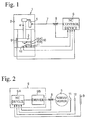
- Fig. 1 is a schematic depiction of a first arrangement of bottom dead centre correction device of a servo press machine in which the bottom dead centre position of the slide is corrected by a bottom dead centre measurement detection from a sensor on a die.
- Fig. 2 is a block diagram associated with the detection device of Fig. 1.
- Fig. 3 is a schematic diagram of a second arrangement of correction device employing a detection of a load on the servo press.
- Fig. 4 is a block diagram associated with the detection device of Fig. 3.
- Fig. 5 is a front view partly in section, showing the construction of the servo press machine.
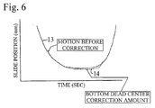
- Fig. 6 illustrates curves representing the slide motion before and after correction.
-
- Referring to the Fig. 1 arrangement, a servo press machine 1
slide 3 is provided on aframe 2 of servo press machine 1 in a vertically free up and down movement manner. Amale screw member 4 is supported in a freely rotating manner on the top part offrame 2 in a vertical reaction. Afemale screw part 3A ofslide 3 and the lower end ofmale screw member 4 are engaged. Screwmember 4 is connected to servomotor 5. -
Servo motor 5 conducts the necessary rotation by a controlled current which is supplied from anNC control device 6 via a powercurrent circuit 7. Servomotor 5 makesslide 3 move vertically in a straight line at a constant stroke viamale screw member 4. - A
current detection device 8 is provided on powercurrent circuit 7. The supplied current value is detected. The detected current value is inputted intoNC control device 6 and is used to calculate the pressure ofslide 3. Furthermore, in order to detect the position ofslide 3 in its vertical movements, a slide position detection device 9, which uses a linear scale, is provided on a part offrame 2 close to oradjacent slide 3. Scale detection device 9 can detect slide position in 1 micron units. - On the lower part of
frame 2, in other words on die 10 which is attached between the bed part andslide 3, a bottom deadcenter detection sensor 11 and atemperature sensor 12 are provided onlower mold 10B. - Bottom dead
center detection sensor 11 detects the over current generated whenupper mold 10A approacheslower mold 10B, and it measures the distance betweenupper mold 10A andlower mold 10B. The measurement precision is 0.1 microns. - The bottom dead center of die 10 can be decided at a position at a constant current value of bottom
dead center sensor 11.Temperature sensor 12 detects the rise in temperature due to molding of die 10. It is used to correct for the temperature drift generated on the detected value of the bottom deadcenter detection sensor 11 due to a temperature rise. Although the bottom deadcenter detection sensor 11 measures the distance betweenupper mold 10A andlower mold 10B by detecting the over current generated whenupper mold 10A approacheslower mold 10B, it has the defect of being an analog system. As described above, corrections for temperature drift and for changes over time become necessary. When using an optical linear scale of a detection value (normally in 0.5-0.1 microns detection units) of slide position detection device 9, the output value of bottom deadcenter detection sensor 11 when it is approaching the die and the detection value of slide position detection device 9 is compared, and the failure of analog type bottom deadcenter detection sensor 11 is determined. - With regard to die 10 which may have different deformations in different parts because of molding, a plurality of bottom dead
center detection sensors 11 can be built in. An average value from these detection values is then calculated. - Furthermore, bottom dead
center detection sensor 11 can be provided onupper mold 10A. - Each of the detection values from slide position detection device 9, bottom dead
center detection sensor 11, andtemperature sensor 12 are inputted intoNC control device 6. - Referring to Fig. 2, the control system for the above construction is shown as a block diagram.
-
NC control device 6 is provided with anNC device 6A and adriver 6B. The detection values fromcurrent detection device 8, bottomdead center sensor 11,temperature sensor 12, and slide position detection device 9 are fed back toNC device 6A and converted to numerical values. These are mathematically operated and used in the control. - The necessary data is saved in memory and reproduced and used.
- Normally, when
slide 3 is moved up and down, a slide motion, in which the top dead center and the bottom dead center are decided onNC device 6A in advance, is set. A set command value is outputted fromNC device 6A at a constant time interval.Driver 6B outputs a current value corresponding to the command value, and this is supplied toservo motor 5. - Vertical motion of
slide 3 is conducted by the rotation ofservo motor 5. The slide motion is controlled by the detection values of the top dead center and bottom dead center detected by slide position detection device 9. - Next, molding is conducted, and when the molded product of the required precision is achieved, the value of the bottom dead center detected by bottom dead
center detection sensor 11 is saved inNC device 6A as the bottom dead center correction amount. The determination of the bottom dead center correction amount is conducted by switching on a correction initiation switch (not shown), which is provided onNC device 6A. An average value from a certain number (set in advance) of molding samplings is saved as the bottom dead center correction amount. - Based on the saved bottom dead center correction amount, the bottom dead center position of the slide motion, which has been set in advance, is corrected.
- The bottom dead center correction amount can be displayed as a numerical value on a setting device not shown.
- A maximum correction amount is determined as the maximum value for correction in order to prevent the breaking of the die. The bottom dead center correction amount is controlled by
NC device 6A so that it does not exceed this value. - When molding is continued, a temperature rise is generated in
die 10. Based on the temperature measurement value detected bytemperature sensor 12, there is correction for the amount of temperature drift of bottom deadcenter detection sensor 11. - The temperature drift is measured in advance for each bottom dead
center detection sensor 11 and is added to the actual bottom dead center correction amount. - Referring to Fig. 6, the bottom dead center of
slide 3, which moves up and down by the command value of the set slide motion, is controlled by feed back of the bottom dead center position of the slide detected by slide position detection device 9. This slide motion ofslide 3 is shown as the solid line of thepre-correction slide motion 13. The bottom dead center correction amount obtained by detections from bottom deadcenter detection sensor 11 andtemperature sensor 12 provided ondie 10 andlower mold 10B is added topre-correction slide motion 13. The corrected slide motion is displayed as a dotted line of correctedslide motion 14. - The bottom dead center of
pre-correction slide motion 13 is controlled by the detection value from slide position detector 9. As a result, it is corrected for fluctuations of the bottom dead center from the distortions inframe 2 and the fluctuations in the bottom dead center due to heat generation in the servo press machine parts. As described above, the bottom dead center precision is 5-10 micrometers. - The bottom dead center precision of corrected
slide motion 14, which is corrected by the bottom dead center correction amount obtained from bottomdead detection sensor 11 provided ondie 10, is in 1 micron unit. - Referring to Fig. 5, the mode of the construction of servo press machine 1 is shown. With
slide 3, guide rods 31, which are erected on the lower surface four corners, are guided in the vertical direction by guides 32 offrame 2. - Timing
pulley 14, which is fastened tomale screw member 4, is connected to timingpulley 15 andtiming belt 16, which are provided on the output shaft ofservo motor 5 which is fastened toframe 2. - An
encoder 17 is connected directly withservo motor 5 and is used in rotation control ofservo motor 5. The rotation angle signal fromencoder 17 is fed back toNC device 16 and used in rotation control of the servo motor. - On the part of
frame 2 adjacent to slide 3, a vertically disposed slide position detection device 9 of a linear scale is mounted. - The opposing
die molds - As is clear from the above description, according to the present invention, because a bottom dead center detection sensor is provided on the die, a bottom dead center precision of 1 micron unit which could not be achieved in the prior art is achieved. A temperature sensor is provided on the die, and temperature drift of the bottom dead center detection sensor due to the temperature rise from molding can also be detected.
- Furthermore, the correction by the bottom dead center detection sensor can be confirmed by conducting measurement of the bottom dead center correction amount anytime during molding. As a result, the bottom dead center precision can be easily maintained.
- Referring to Figs. 3 and 4, a second embodiment of the present invention of a device for correcting the bottom dead center by detecting the load of a servo press is described.
- Referring to Fig. 4, a control system for
servo motor 5 which controls the ascending and descending motion ofslide 3 is shown.NC control device 6 is constructed from the following: aNC device 6A, which outputs pre-set NC signals; and adriver 6B, which outputs a current corresponding to the NC signals outputted fromNC device 6A and drives and controlsservo motor 5. - In addition, there is feedback to
NC device 6A of signals indicating the current value, which represents the slide load detected bycurrent detection device 8, and the slide position, which is detected by scale detection device 9. By conducting calculations with these values, a correction value is obtained and is outputted as a NC signal. A current corresponding to this NC signal is outputted todriver 6B and is used in the rotation control ofservo motor 5. - The molding load of
slide 3 can be calculated by the following method: a distortion measure is attached toframe 2; and the distortion measure output resulting from the load during molding is inputted intoNC device 6A. The molding load can be detected by other methods as well. - In addition, a die
upper mold 10A is attached to the lower surface ofslide 3. A dielower mold 10B is attached to the upper surface of a bolster, which has been mounted on top of a bed offrame 2. The touch point is where dieupper mold 10A reaches the processing material, which has been supplied on top of dielower mold 10B. At this touch point, a rise in the current value due to the initiation of molding is detected bycurrent detection device 8. This is inputted intoNC device 6A and is used in the rotation control ofservo motor 5. - Details of the bottom dead center correction with the second embodiment now will be described. In the first bottom dead center correction method by the detection of the load with respect to the changes in the hardness of the processing material, first,
slide 3 is lowered, and molding is initiated. When the load value ofslide 3, as calculated byNC device 6A, reaches a pre-set load value, the slide position detected by scale detection device 9 and a pre-set slide position are compared. - If the detected slide position is higher than the pre-set position, the hardness of the processing material is determined to be higher than the standard hardness. The difference in the slide position, corresponding to the difference with the standard value of hardness, is detected, and the set bottom dead center of
slide 3 is corrected so that it is lower, and molding is conducted by loweringslide 3 to the corrected bottom dead center. Furthermore, correction values are determined by data obtained beforehand by molding processing materials having a standard value of hardness and materials having values different from the standard value. These are saved inNC device 6 and used for the pre-set load value and slide position. - Conversely, when the slide position is lower than the pre-set position, the hardness of the processing material is determined to be lower than the standard hardness. The difference in the slide position, corresponding to the difference with the standard value of hardness, is detected, and the set bottom dead center of
slide 3 is corrected so that it is higher, and molding is conducted by loweringslide 3 to the corrected bottom dead center. The correction value of the bottom dead center corresponding to the difference with the standard value of hardness is determined as described previously by data obtained by molding processing materials having a standard value of hardness and materials having values different from the standard value. With this correction, the bottom dead center precision ofslide 3 can be in the range of one to a few microns. - In the second method for bottom dead center correction by detection of the load with respect to changes in the hardness of the processing material, first,
slide 3 is lowered, and molding is initiated. When the slide position detected by scale detection device 9 reaches a pre-set slide position, the load value, which is calculated byNC device 6A from the current value detected bycurrent detection device 8, and a pre-set load value are compared. - If the calculated load value is higher than the pre-set load value, the hardness of the processing material is determined to be higher than the standard hardness. The difference in the load value, corresponding to the difference with the standard value of hardness, is detected, and the set bottom dead center of
slide 3 is corrected so that it is lower. Molding is conducted by loweringslide 3 to the corrected bottom dead center. As described previously, the pre-set load values and slide positions are determined by data obtained beforehand by molding processing materials with a standard value of hardness and materials having values different from the standard value. - Conversely, when the load value is lower than the pre-set load value, the hardness of the processing material is determined to be lower than the standard hardness. The difference in load value, corresponding to the difference with the standard value of hardness, is detected, and the set bottom dead center of
slide 3 is corrected so that it is higher. Molding is conducted by loweringslide 3 to the corrected bottom dead center. The hardness of the processing material is often slightly higher at the leading end and the tail end of the coil material. The middle part is approximately uniform, and there may be areas which have a lower hardness. - The standard hardness of the processing material is determined to be the hardness of an approximately uniform portion in the middle of the coil. A hardness is determined to be higher or lower. As described previously, the bottom dead center correction value, which responds to the fluctuation in the load value due to differences in hardness, is determined by data obtained beforehand by molding processing materials with a standard value of hardness and materials of a hardness different from the standard value. With this correction, the bottom dead center precision of
slide 3 can be in the range of one to a few microns. - We have stated up to this point that the thickness of the processing material is uniform, but the thickness of the coil material can change some. If the thickness changes, the molding load values at the same bottom dead center position can fluctuate. First, during the lowering of
slide 3, the touch point, which is the point whereupper mold 10A reaches the processing material supplied on top oflower mold 10B, is detected bycurrent detection device 8 as a rise in the current value due to the initiation of molding. - At this time, if the slide position detected by scale detection device 9 is the standard value, or in other words, if the thickness is the standard value, the set bottom dead center of
slide 3 is not corrected, and molding is conducted by loweringslide 3 to the pre-set bottom dead center. On the other hand, if the slide position is higher than the standard value, the thickness is determined to be thick. The set bottom dead center ofslide 3 is corrected, and molding is conducted by loweringslide 3 to a corrected set bottom dead center. Conversely, if the slide position is lower than the standard value, the thickness is determined to be thin, and the set bottom dead center ofslide 3 is corrected, and molding is conducted by raisingslide 3 to the corrected set bottom dead center. - The correction of the set bottom dead center due to changes in thickness of the processing material can be used in combination with one of either the first or second method for bottom dead center correction by detecting a load in response to changes in the hardness of the processing material. Therefore, a combination can be selected and used by a setting device provided on
NC control device 6 of servo press 1. - Referring to Fig. 6, a slide motion from the lowering to the raising of
slide 3 is shown. The X-axis is the time axis (SEC), and the Y-axis is the slide position axis (MM). The curve shown as the pre-correction slide motion is the curve of the prior art example with a bottom dead center precision of 5-10 microns. - When correcting by detection of a load in response to changes in the hardness of the processing material and correcting for thickness, the curve of the slide motion becomes the curve shown by the dotted line. Therefore, as described above, with these corrections, the bottom dead center precision is improved and is in the range of one to a few microns. The correction amount is displayed on the screen as the "current correction value".
- The above describes one embodiment for a method in which the load is detected by the current in the servo motor, but the actual load can also be detected, for example, by a
load cell 18 or the like. In other words, based on the above technical idea, modifications of the design in the construction and detailed parts are included in the present invention. - In the bottom dead center correction device of the prior art, the set bottom dead center is corrected by detecting the fluctuation of the slide position, and the bottom dead center precision is 5-10 microns. In contrast, as is clear from the above description, according to the present invention, by correcting the set bottom dead center by the fluctuation in the molding load, fluctuations in the set bottom dead center due to deformation of all of the construction parts, which includes not only the servo press but also the die, can be corrected. There are considerable advantages to improving the bottom dead center precision to a range of 1 to a few microns.
- Having described preferred embodiments of the present invention with reference to the accompanying drawings, it is to be understood that the invention is not limited to those precise embodiments, and that various changes and modifications may be effected therein by one skilled in the art without departing from the scope or spirit of the invention as defined in the appended claims.
Claims (16)
- A bottom dead center correction device for a servo press machine, the servo press machine having a servo motor as a drive source theref or, the servo motor controlling vertical linear motion of asaid bottom dead center position of said slide is corrected by a bottom dead center measurement value detected from at least one bottom dead center detection sensor provided on a die of the screw press machine.press slide based on a set top dead center position and abottom dead center position of said slide, wherein:
- A bottom dead center correction device for a servo press machine as described in Claim 1, including:a temperature sensor detecting a temperature rise value of said die so that a temperature drift of said bottom dead center detection sensor can be corrected.
- A bottom dead center correction device for a servo press machine as described in Claim 1, including:a position detection device which detects a position of said slide,a detected value from said position detection device being comparable with an output value from said bottom dead center detection sensor for verifying a detection precision of said bottom dead center detection sensor whereby a failure of said bottom dead center detection sensor can be determined.
- A device for correcting a bottom dead center by detecting a molding load in a servo press, said servo press, which has a servo motor with numerical control as a drive source, providing a raising and lowering motion of a slide, comprising:when one of a slide load value, which is calculated from a current value inputted from said current detection device, and a slide position, which is inputted from said scale detection device, reaches a set value, said NC control device corrects a set bottom dead center of said slide according to a difference arising between the said one of said slide load value and the slide position and a respective set value of each.(a) a scale detection device, which detects a position of said slide in a vertical direction and which outputs an electrical position signal;(b) a current detection device, which detects a current value indicative of molding load supplied to said servo motor;an NC control device, which controls a rise and fall motion of said slide by controlling the current value that is supplied to said servo motor so that it corresponds to a pre-set slide motion;
- A device for correcting a bottom dead center by detecting a molding load in a servo press as described in Claim 4, wherein:when said slide load value, which is calculated by said NC control device, reaches a pre-set value, if a slide position, which is outputted from said scale detection device, is higher than a pre-set position, the material to be processed is determined to have a high hardness, and a set bottom dead center of said slide is corrected downward by an amount of said correction value, and said slide is lowered;conversely, if said position is lower than a pre-set position, the processing material is determined to have a low hardness, and a set bottom dead center of said slide is corrected upward by an amount of said correction value, and said slide is lowered.
- A device for correcting a bottom dead center by detecting a molding load in a servo press as described in Claim 4, wherein:when a slide position, which is outputted from said scale detection device, reaches a pre-set slide position, if a load value, which is calculated by said NC control device, is larger than a pre-set load value, the material to be processed is determined to have a high hardness, and a set bottom dead center of said slide is corrected downward by an amount of said correction value, and said slide is lowered;conversely, if said load value is lower than a pre-set load value, the processing material is determined to have a low hardness, and a set bottom dead center of said slide is corrected upward by an amount of said correction value, and said slide is lowered.
- A device for correcting a bottom dead center by detecting a molding load in a servo press as described in Claim 4, wherein:a touch point, where an upper mold which is lowered together with said slide contacts a processing material supplied onto a lower mold, is detected by a rise in a current value outputted from said current detection device;when said touch point is detected, a corrected value for a set bottom dead center of said slide obtained from an output of said scale detection device can be corrected.
- A device for correcting a bottom dead center by detecting a molding load in a servo press, said servo press, which has a servo motor with numerical control as a drive source, providing a raising and lowering motion of a slide, comprising:when one of a slide load value, which is detected by said load detection cell, and a slide position, which is inputted from said scale detection device, reaches a set value, said NC control device corrects a set bottom dead center of said slide according to a difference arising between the said one of said slide load value and the slide position and a respective set value of each.(a) a scale detection device, which detects a position of said slide in a vertical direction and which outputs an electrical position signal;(b) a load detection cell which detects a slide load value;
an NC control device, which controls a rise and fall motion of said slide by controlling the current value that is supplied to said servo motor so that it corresponds to a pre-set slide motion; - Apparatus for adjusting a bottom dead centre position of a slide in a machine tool of the type in which the slide is moved in operation with respect to a machine tool frame between a top dead centre position and a bottom dead centre position; said apparatus comprising:-actuator means for moving said slide in operation;position detection means for determining a position of said slide with respect to the said machine tool frame;load detection means for determining a load value applied to said slide by said actuator means;determining means for determining a bottom dead centre adjustment position for said slide in response to either said slide being moved in operation beyond a pre-determined slide position or said load value exceeding a pre-determined load value.
- Apparatus according to claim 9 wherein said bottom dead centre adjustment position is determined in accordance with the difference between the said slide position and said respective pre-determined position or the said load and said respective pre-determined load.
- Apparatus according to 9 or 10 wherein said slide is arranged to apply pressure to a workpiece in said machine tool and said apparatus means is arranged to adjust said bottom dead centre position in response to detected variations in workpiece material hardness or thickness characteristics.
- Apparatus according to any one of claims 9 to 11 wherein said apparatus is arranged to adjust said bottom dead centre position in one direction in response to said slide being positioned between said pre-determined position and said top dead centre position when said load is increased to the value of the said pre-determined load value, and to adjust said bottom dead centre position in the opposite direction thereof in response to said slide being positioned between said pre-determined position and said bottom dead centre position.
- Apparatus according to claim any one of claims 9 to 12 wherein wherein said apparatus is arranged to adjust said bottom dead centre position in one direction in response to movement of said slide to said pre-determined position when said detected load applied to said slide is less than said pre-determined load, and in the opposite direction thereof when said detected load is greater than said pre-determined. load.
- Apparatus according to any one of claims 9 to 13 wherein said apparatus comprises an upper mold movable with the said slide and a lower mold, and detection means for detecting the position of said slide when said upper mold contacts a workpiece positioned on the lower mold, and wherein said apparatus is arranged to adjust said bottom dead centre position in accordance with the position of said slide when said contact is detected.
- A method for adjusting a bottom dead centre position of a slide in a machine tool of the type in which the slide is moved in operation with respect to a machine tool frame between a top dead centre position and a bottom dead centre position; said apparatus having: actuator means for moving said slide in operation; position detection means for determining a position of said slide with respect to a frame of said machine tool; and load detection means for determining a load value applied to said slide by said actuator means; wherein said method comprises the steps of:-determining the position of said slide with respect to the said machine tool frame;determining the load value applied to said slide by said actuator means; anddetermining a bottom dead centre adjustment position for said slide in response to either said slide being moved beyond a pre-determined slide position or said load value exceeding a pre-determined load value.
- A method according to claim 15 wherein said bottom dead centre adjustment position is determined in accordance with the difference between the said slide position and said respective pre-determined position or the said load and said respective pre-determined load.
Priority Applications (6)
| Application Number | Priority Date | Filing Date | Title |
|---|---|---|---|
| US09/688,576 US6619088B1 (en) | 2000-10-16 | 2000-10-16 | Bottom dead center correction device for servo press machine |
| EP05003258A EP1537988B1 (en) | 2000-10-30 | 2000-10-30 | Bottom dead centre correction device for servo press machines |
| EP00309570A EP1201416B1 (en) | 2000-10-16 | 2000-10-30 | Bottom dead center correction device for servo press machine |
| DE60041559T DE60041559D1 (en) | 2000-10-30 | 2000-10-30 | Device for adjusting the position of the lowest dead center for a servomotor driven press |
| DE60041447T DE60041447D1 (en) | 2000-10-30 | 2000-10-30 | Device for adjusting the position of the lowest dead center for a servomotor driven press |
| SG200006268A SG92751A1 (en) | 2000-10-16 | 2000-10-31 | Bottom dead center correction device for servo press machine |
Applications Claiming Priority (3)
| Application Number | Priority Date | Filing Date | Title |
|---|---|---|---|
| US09/688,576 US6619088B1 (en) | 2000-10-16 | 2000-10-16 | Bottom dead center correction device for servo press machine |
| EP00309570A EP1201416B1 (en) | 2000-10-16 | 2000-10-30 | Bottom dead center correction device for servo press machine |
| SG200006268A SG92751A1 (en) | 2000-10-16 | 2000-10-31 | Bottom dead center correction device for servo press machine |
Related Child Applications (1)
| Application Number | Title | Priority Date | Filing Date |
|---|---|---|---|
| EP05003258A Division EP1537988B1 (en) | 2000-10-30 | 2000-10-30 | Bottom dead centre correction device for servo press machines |
Publications (2)
| Publication Number | Publication Date |
|---|---|
| EP1201416A1 true EP1201416A1 (en) | 2002-05-02 |
| EP1201416B1 EP1201416B1 (en) | 2009-01-21 |
Family
ID=29718576
Family Applications (1)
| Application Number | Title | Priority Date | Filing Date |
|---|---|---|---|
| EP00309570A Expired - Lifetime EP1201416B1 (en) | 2000-10-16 | 2000-10-30 | Bottom dead center correction device for servo press machine |
Country Status (3)
| Country | Link |
|---|---|
| US (1) | US6619088B1 (en) |
| EP (1) | EP1201416B1 (en) |
| SG (1) | SG92751A1 (en) |
Cited By (7)
| Publication number | Priority date | Publication date | Assignee | Title |
|---|---|---|---|---|
| EP1516685A1 (en) * | 2003-09-18 | 2005-03-23 | Baltec Maschinenbau Ag | Method for the automatic compensation of the frame deflection within riveting machines |
| WO2007022755A3 (en) * | 2005-08-24 | 2007-05-10 | Mueller Weingarten Maschf | Method and device for controlling and adjusting forces on servo-electric presses |
| EP1849590A1 (en) * | 2006-04-29 | 2007-10-31 | Fette GmbH | Press |
| WO2007144210A1 (en) * | 2006-06-16 | 2007-12-21 | Siemens Aktiengesellschaft | Method and device for determining the press force in a press |
| WO2008071154A3 (en) * | 2006-12-15 | 2008-09-12 | Mueller Weingarten Maschf | Method and device for the control and regulation of position deviations of tappets in servoelectric presses |
| CN102183311A (en) * | 2010-12-17 | 2011-09-14 | 东南大学 | Press dynamic thermal error measuring device and method |
| CN106696328A (en) * | 2017-01-16 | 2017-05-24 | 爱克(苏州)机械有限公司 | Main drive for double-servo numerical-control turret punch press |
Families Citing this family (17)
| Publication number | Priority date | Publication date | Assignee | Title |
|---|---|---|---|---|
| JP2003117700A (en) * | 2001-10-10 | 2003-04-23 | Komatsu Ltd | Overload protection control method for press machine |
| DE102004043776B3 (en) * | 2004-09-10 | 2006-06-14 | Bernhard Schäfer Werkzeug- und Sondermaschinenbau GmbH | Motor-driven crimping device |
| JP5042240B2 (en) * | 2006-02-06 | 2012-10-03 | エー ビー ビー リサーチ リミテッド | Mechanical press drive system |
| ES2452022T3 (en) * | 2006-02-06 | 2014-03-31 | Abb Research Ltd. | Press line system and method |
| EP2218171A4 (en) * | 2007-11-09 | 2012-03-21 | Vamco Int Inc | APPARATUS AND METHOD FOR TRAINING FOR A PRESS |
| JP5138399B2 (en) * | 2008-01-25 | 2013-02-06 | アイダエンジニアリング株式会社 | Servo press machine |
| US9061435B1 (en) * | 2009-09-10 | 2015-06-23 | Colter & Peterson, Inc. | Automated knife change adjustment on dual-gearbox paper cutting machines |
| WO2011065951A1 (en) * | 2009-11-30 | 2011-06-03 | Michelin Recherche Et Technique S.A. | Method of controlling product volume in a fixed volume mold |
| US9250050B2 (en) | 2011-10-21 | 2016-02-02 | Setpoint Systems, Inc. | Apparatus, system, and method for ammunition cartridge case annealing |
| US9157709B2 (en) | 2011-12-08 | 2015-10-13 | Setpoint Systems, Inc. | Apparatus, system, and method for manufacturing ammunition cartridge cases |
| JP6134810B2 (en) * | 2012-12-18 | 2017-05-24 | コンパニー ゼネラール デ エタブリッスマン ミシュラン | Grafting functional group species onto rubber |
| JP6537308B2 (en) * | 2015-03-13 | 2019-07-03 | 蛇の目ミシン工業株式会社 | Servo press, control method and program |
| US9908171B2 (en) | 2015-11-25 | 2018-03-06 | Btm Company Llc | Linkage press machine |
| CN110270630A (en) * | 2019-06-12 | 2019-09-24 | 芜湖市恒浩机械制造有限公司 | A kind of stamping equipment for automobile right angle triangle |
| CN110654057B (en) * | 2019-10-25 | 2025-04-18 | 济宁科力光电产业有限责任公司 | A device and method for automatic calibration of servo press position |
| JP7576412B2 (en) * | 2020-08-17 | 2024-10-31 | 株式会社ジャノメ | Press Equipment |
| JP7609645B2 (en) * | 2021-01-22 | 2025-01-07 | 株式会社アマダ | Press system and method for controlling press system |
Citations (10)
| Publication number | Priority date | Publication date | Assignee | Title |
|---|---|---|---|---|
| US5087398A (en) * | 1988-10-20 | 1992-02-11 | Adl Automation Zone Industrielle | Process and apparatus for compressing, and monitoring the compression of, pulverulent materials and a press applying same |
| JPH1015698A (en) * | 1996-07-02 | 1998-01-20 | Nec Corp | Device for detecting bottom dead point of press device |
| US5746122A (en) * | 1995-05-04 | 1998-05-05 | Maschinenfabrik Gietz Ag | Embossing machine |
| US5829347A (en) * | 1996-05-21 | 1998-11-03 | Janome Sewing Machine Co., Ltd. | Electropressing apparatus |
| US5887469A (en) * | 1996-07-31 | 1999-03-30 | Yazaki Corporation | Terminal crimping device |
| JPH11123600A (en) * | 1997-10-20 | 1999-05-11 | Aida Eng Ltd | Forming controller for servo press |
| JPH11291100A (en) * | 1998-04-08 | 1999-10-26 | Aida Eng Ltd | Die preload setting device of servo press |
| JP2000246498A (en) * | 1999-02-26 | 2000-09-12 | Aida Eng Ltd | Measuring and display device of load and forming speed of servo press machine |
| JP2000263299A (en) * | 1999-03-15 | 2000-09-26 | Aida Eng Ltd | Automatic parameter adjusting device of servo press |
| JP2000280100A (en) * | 1999-03-31 | 2000-10-10 | Aida Eng Ltd | Bottom dead point correcting device of servo press machine |
Family Cites Families (15)
| Publication number | Priority date | Publication date | Assignee | Title |
|---|---|---|---|---|
| US4936126A (en) * | 1988-05-17 | 1990-06-26 | Daiichi Electric Co., Ltd. | Press brake with a displacement sensor of electric signal output |
| DE3842009C1 (en) * | 1988-11-22 | 1990-03-22 | Kabelwerke Reinshagen Gmbh, 5600 Wuppertal, De | |
| US5199290A (en) * | 1989-10-19 | 1993-04-06 | Aida Engineering, Ltd. | Method of automatic adjustment of die height of a press |
| US5271254A (en) * | 1989-12-05 | 1993-12-21 | The Whitaker Corporation | Crimped connector quality control method apparatus |
| GB9012058D0 (en) * | 1990-05-30 | 1990-07-18 | Amp Gmbh | Method of,and apparatus for,controlling the crimp height of crimped electrical connections |
| US5123165A (en) * | 1991-03-21 | 1992-06-23 | Amp Incorporated | Method of determining the crimp height of a crimped electrical connection |
| JPH0729223B2 (en) * | 1991-06-28 | 1995-04-05 | アイダエンジニアリング株式会社 | Bottom dead center position correction device for press machine |
| US5697146A (en) * | 1994-12-28 | 1997-12-16 | Yazaki Corporation | Apparatus for crimping terminal to electrical wire |
| US5727409A (en) * | 1994-12-28 | 1998-03-17 | Yazaki Corporation | Method of controlling a terminal crimping apparatus |
| US5669257A (en) * | 1994-12-28 | 1997-09-23 | Yazaki Corporation | Method of crimping terminal and apparatus for the same |
| JP3537059B2 (en) * | 1995-01-31 | 2004-06-14 | 株式会社小松製作所 | Press die height correction device |
| JP2860935B2 (en) | 1996-05-30 | 1999-02-24 | 株式会社小松製作所 | Press die height correction device |
| JP3156841B2 (en) * | 1996-06-12 | 2001-04-16 | 矢崎総業株式会社 | Control method of terminal crimping device |
| JPH1015699A (en) | 1996-07-05 | 1998-01-20 | Komatsu Ltd | Press die height correction device |
| JPH10249599A (en) | 1997-03-07 | 1998-09-22 | Takeshita Sangyo Kk | Press machine |
-
2000
- 2000-10-16 US US09/688,576 patent/US6619088B1/en not_active Expired - Fee Related
- 2000-10-30 EP EP00309570A patent/EP1201416B1/en not_active Expired - Lifetime
- 2000-10-31 SG SG200006268A patent/SG92751A1/en unknown
Patent Citations (10)
| Publication number | Priority date | Publication date | Assignee | Title |
|---|---|---|---|---|
| US5087398A (en) * | 1988-10-20 | 1992-02-11 | Adl Automation Zone Industrielle | Process and apparatus for compressing, and monitoring the compression of, pulverulent materials and a press applying same |
| US5746122A (en) * | 1995-05-04 | 1998-05-05 | Maschinenfabrik Gietz Ag | Embossing machine |
| US5829347A (en) * | 1996-05-21 | 1998-11-03 | Janome Sewing Machine Co., Ltd. | Electropressing apparatus |
| JPH1015698A (en) * | 1996-07-02 | 1998-01-20 | Nec Corp | Device for detecting bottom dead point of press device |
| US5887469A (en) * | 1996-07-31 | 1999-03-30 | Yazaki Corporation | Terminal crimping device |
| JPH11123600A (en) * | 1997-10-20 | 1999-05-11 | Aida Eng Ltd | Forming controller for servo press |
| JPH11291100A (en) * | 1998-04-08 | 1999-10-26 | Aida Eng Ltd | Die preload setting device of servo press |
| JP2000246498A (en) * | 1999-02-26 | 2000-09-12 | Aida Eng Ltd | Measuring and display device of load and forming speed of servo press machine |
| JP2000263299A (en) * | 1999-03-15 | 2000-09-26 | Aida Eng Ltd | Automatic parameter adjusting device of servo press |
| JP2000280100A (en) * | 1999-03-31 | 2000-10-10 | Aida Eng Ltd | Bottom dead point correcting device of servo press machine |
Non-Patent Citations (6)
| Title |
|---|
| DATABASE WPI Section PQ Week 200059, Derwent World Patents Index; Class P71, AN 2000-615288, XP002163886 * |
| DATABASE WPI Section PQ Week 200061, Derwent World Patents Index; Class P71, AN 2000-635088, XP002163887 * |
| DATABASE WPI Section PQ Week 200066, Derwent World Patents Index; Class P71, AN 2000-676086, XP002163885 * |
| PATENT ABSTRACTS OF JAPAN vol. 1998, no. 05 30 April 1998 (1998-04-30) * |
| PATENT ABSTRACTS OF JAPAN vol. 1999, no. 10 31 August 1999 (1999-08-31) * |
| PATENT ABSTRACTS OF JAPAN vol. 2000, no. 01 31 January 2000 (2000-01-31) * |
Cited By (9)
| Publication number | Priority date | Publication date | Assignee | Title |
|---|---|---|---|---|
| EP1516685A1 (en) * | 2003-09-18 | 2005-03-23 | Baltec Maschinenbau Ag | Method for the automatic compensation of the frame deflection within riveting machines |
| WO2007022755A3 (en) * | 2005-08-24 | 2007-05-10 | Mueller Weingarten Maschf | Method and device for controlling and adjusting forces on servo-electric presses |
| CN101248399B (en) * | 2005-08-24 | 2012-12-12 | 米勒魏因加滕股份公司 | Method and device for controlling and regulating the force of a servo-electric press |
| EP1849590A1 (en) * | 2006-04-29 | 2007-10-31 | Fette GmbH | Press |
| US7726961B2 (en) | 2006-04-29 | 2010-06-01 | Fette Gmbh | Press |
| WO2007144210A1 (en) * | 2006-06-16 | 2007-12-21 | Siemens Aktiengesellschaft | Method and device for determining the press force in a press |
| WO2008071154A3 (en) * | 2006-12-15 | 2008-09-12 | Mueller Weingarten Maschf | Method and device for the control and regulation of position deviations of tappets in servoelectric presses |
| CN102183311A (en) * | 2010-12-17 | 2011-09-14 | 东南大学 | Press dynamic thermal error measuring device and method |
| CN106696328A (en) * | 2017-01-16 | 2017-05-24 | 爱克(苏州)机械有限公司 | Main drive for double-servo numerical-control turret punch press |
Also Published As
| Publication number | Publication date |
|---|---|
| US6619088B1 (en) | 2003-09-16 |
| EP1201416B1 (en) | 2009-01-21 |
| SG92751A1 (en) | 2002-11-19 |
Similar Documents
| Publication | Publication Date | Title |
|---|---|---|
| EP1201416A1 (en) | Bottom dead center correction device for servo press machine | |
| EP0987092B1 (en) | Clamping controller | |
| JP5759792B2 (en) | Mold clamping device, molding machine, mold platen, mold clamping device control method, and mold platen control method | |
| EP1537988B1 (en) | Bottom dead centre correction device for servo press machines | |
| JP3537059B2 (en) | Press die height correction device | |
| JP2001121297A (en) | Sliding correction device for press machine | |
| CN1640648A (en) | Mold protection method for mold clamping apparatus | |
| JP3868207B2 (en) | Servo press bottom dead center correction method | |
| JP3692261B2 (en) | Bottom dead center correction device by servo press load | |
| JP2000280100A (en) | Bottom dead point correcting device of servo press machine | |
| JP5002229B2 (en) | Clamping device | |
| JP4118428B2 (en) | Control method of electric resin molding machine | |
| JP2860935B2 (en) | Press die height correction device | |
| JPH05138254A (en) | Method and equipment for measuring plate thickness in bender | |
| JPH11123600A (en) | Forming controller for servo press | |
| KR20160134901A (en) | A Servo die cushion apparatus have the control accuracy improvement function | |
| JPH08323826A (en) | Mold compression molding method for thin molded products | |
| JP7753686B2 (en) | Press machine and press machine control method | |
| JP2000271655A (en) | Bending method and bending device | |
| JP3687952B2 (en) | Servo press bottom dead center correction device | |
| KR102415687B1 (en) | Forming device with motion controller | |
| JPH11226796A (en) | High precision C type frame press | |
| JP4322976B2 (en) | Bending method and bending machine by bending load control system | |
| JPH0714560B2 (en) | Press machine | |
| JP2001277248A (en) | Mold clamping device, method for measuring mold clamping force, and method for adjusting mold clamping force |
Legal Events
| Date | Code | Title | Description |
|---|---|---|---|
| PUAI | Public reference made under article 153(3) epc to a published international application that has entered the european phase |
Free format text: ORIGINAL CODE: 0009012 |
|
| AK | Designated contracting states |
Kind code of ref document: A1 Designated state(s): DE GB Kind code of ref document: A1 Designated state(s): AT BE CH CY DE DK ES FI FR GB GR IE IT LI LU MC NL PT SE |
|
| AX | Request for extension of the european patent |
Free format text: AL;LT;LV;MK;RO;SI |
|
| 17P | Request for examination filed |
Effective date: 20021001 |
|
| AKX | Designation fees paid |
Free format text: DE GB |
|
| 17Q | First examination report despatched |
Effective date: 20040803 |
|
| 17Q | First examination report despatched |
Effective date: 20040803 |
|
| GRAP | Despatch of communication of intention to grant a patent |
Free format text: ORIGINAL CODE: EPIDOSNIGR1 |
|
| GRAS | Grant fee paid |
Free format text: ORIGINAL CODE: EPIDOSNIGR3 |
|
| GRAA | (expected) grant |
Free format text: ORIGINAL CODE: 0009210 |
|
| AK | Designated contracting states |
Kind code of ref document: B1 Designated state(s): DE GB |
|
| REG | Reference to a national code |
Ref country code: GB Ref legal event code: FG4D |
|
| REF | Corresponds to: |
Ref document number: 60041447 Country of ref document: DE Date of ref document: 20090312 Kind code of ref document: P |
|
| PLBE | No opposition filed within time limit |
Free format text: ORIGINAL CODE: 0009261 |
|
| STAA | Information on the status of an ep patent application or granted ep patent |
Free format text: STATUS: NO OPPOSITION FILED WITHIN TIME LIMIT |
|
| 26N | No opposition filed |
Effective date: 20091022 |
|
| PGFP | Annual fee paid to national office [announced via postgrant information from national office to epo] |
Ref country code: GB Payment date: 20101025 Year of fee payment: 11 |
|
| PGFP | Annual fee paid to national office [announced via postgrant information from national office to epo] |
Ref country code: DE Payment date: 20121024 Year of fee payment: 13 |
|
| GBPC | Gb: european patent ceased through non-payment of renewal fee |
Effective date: 20121030 |
|
| PG25 | Lapsed in a contracting state [announced via postgrant information from national office to epo] |
Ref country code: GB Free format text: LAPSE BECAUSE OF NON-PAYMENT OF DUE FEES Effective date: 20121030 |
|
| REG | Reference to a national code |
Ref country code: DE Ref legal event code: R119 Ref document number: 60041447 Country of ref document: DE Effective date: 20140501 |
|
| PG25 | Lapsed in a contracting state [announced via postgrant information from national office to epo] |
Ref country code: DE Free format text: LAPSE BECAUSE OF NON-PAYMENT OF DUE FEES Effective date: 20140501 |