EP1201826A1 - Machine de vissage ou de dévissage de boulons ou de tire-fond pour attaches vissées de voies ferrées - Google Patents
Machine de vissage ou de dévissage de boulons ou de tire-fond pour attaches vissées de voies ferrées Download PDFInfo
- Publication number
- EP1201826A1 EP1201826A1 EP01420213A EP01420213A EP1201826A1 EP 1201826 A1 EP1201826 A1 EP 1201826A1 EP 01420213 A EP01420213 A EP 01420213A EP 01420213 A EP01420213 A EP 01420213A EP 1201826 A1 EP1201826 A1 EP 1201826A1
- Authority
- EP
- European Patent Office
- Prior art keywords
- machine
- heads
- screwing
- group
- chassis
- Prior art date
- Legal status (The legal status is an assumption and is not a legal conclusion. Google has not performed a legal analysis and makes no representation as to the accuracy of the status listed.)
- Granted
Links
- 238000006073 displacement reaction Methods 0.000 claims abstract description 10
- 239000000463 material Substances 0.000 claims description 3
- 239000012530 fluid Substances 0.000 claims description 2
- 230000008901 benefit Effects 0.000 description 2
- 210000004417 patella Anatomy 0.000 description 2
- 206010003830 Automatism Diseases 0.000 description 1
- 241001669679 Eleotris Species 0.000 description 1
- 230000006378 damage Effects 0.000 description 1
- 230000001687 destabilization Effects 0.000 description 1
- 230000000694 effects Effects 0.000 description 1
- 238000000034 method Methods 0.000 description 1
- 230000003387 muscular Effects 0.000 description 1
- 230000035939 shock Effects 0.000 description 1
Images


Classifications
-
- E—FIXED CONSTRUCTIONS
- E01—CONSTRUCTION OF ROADS, RAILWAYS, OR BRIDGES
- E01B—PERMANENT WAY; PERMANENT-WAY TOOLS; MACHINES FOR MAKING RAILWAYS OF ALL KINDS
- E01B29/00—Laying, rebuilding, or taking-up tracks; Tools or machines therefor
- E01B29/24—Fixing or removing detachable fastening means or accessories thereof; Pre-assembling track components by detachable fastening means
- E01B29/28—Fixing or removing detachable fastening means or accessories thereof; Pre-assembling track components by detachable fastening means the fastening means being of screw-and-nut type; Apparatus therefor, adapted to additionally drilling holes
-
- B—PERFORMING OPERATIONS; TRANSPORTING
- B23—MACHINE TOOLS; METAL-WORKING NOT OTHERWISE PROVIDED FOR
- B23P—METAL-WORKING NOT OTHERWISE PROVIDED FOR; COMBINED OPERATIONS; UNIVERSAL MACHINE TOOLS
- B23P19/00—Machines for simply fitting together or separating metal parts or objects, or metal and non-metal parts, whether or not involving some deformation; Tools or devices therefor so far as not provided for in other classes
- B23P19/04—Machines for simply fitting together or separating metal parts or objects, or metal and non-metal parts, whether or not involving some deformation; Tools or devices therefor so far as not provided for in other classes for assembling or disassembling parts
- B23P19/06—Screw or nut setting or loosening machines
Definitions
- the subject of the present invention is a screwing machine or for unscrewing bolts or lag screws for screwed track fasteners railway.
- the rails of the railway tracks rest on sleepers on which they are fixed by fasteners.
- a railroad track presenting, cross-sectional view, an enlarged lower part consisting of two pads arranged on either side of the central part of the rail and taking support on the crosspieces, fasteners take support on the pads arranged on either side of the central part of it.
- These fasteners are fixed on the sleepers supporting the rails by means of lag screws or by nuts engaged on threaded rods, previously made integral sleepers, and on which the fasteners are engaged.
- Such a machine is known, for example, from the documents EP 0 169 753 and FR 2 745 216, in the name of the Applicant.
- the simplest machine in its structure includes a key designed to operate only one bolt at a time. Such a machine rolls on the rail to be fixed, and is handled by hand by a operator.
- the invention relates to a screwing or unscrewing machine of bolts or lag screws for screwed fasteners of railways, which has four heads for simultaneously operating the four lag screws or bolts for fixing four fasteners of a rail on the same crosses.
- Such a machine is far too heavy to be operated from one cross to the other by the simple muscular force of an operator. he should therefore be equipped with a self-driving system.
- the operator comes to cap the bolt or the lag screw with the wrench of the clamping head, which requires a combination of several movements. This combination is difficult to implement when the machine has to move by itself.
- Other difficulties add.
- a machine with four heads being intended to clamp simultaneously the four fasteners of the same crosspiece, this operation must be carried out quickly, although the ties are usually not perfectly square to the rail, that their spacing is not perfectly regular, which can vary by a few centimeters, and that they are, for some, several centimeters below their final level.
- the invention relates to a screwing or unscrewing machine bolts or lag screws for screwed railroad fasteners, comprising four heads intended to actuate the four simultaneously bolts or the four lag screws intended to secure a rail to a crossing.
- the object of the invention is to produce a structural machine simple, which proceeds to an automatic positioning of the heads opposite bolts, and which benefits from high reliability.
- the machine moves by a value corresponding to the distance between two crosspieces, the machine stopping depending on the distance traveled, which is predetermined and adjustable, and not of the search using sensors for positioning with respect to bolts or lag screws to operate. If some of the screw heads are not perfectly opposite the corresponding bolts, the possibility of inclination of the corresponding keys allows their engagement on the bolts. When driving the rotating keys, the stress exerted on the axes driving the keys will result in a realignment of the key with the corresponding screw head, thanks to the possibility of longitudinal movement on the chassis of the screw head group considered.
- the chassis comprises four rollers, each provided with a bandage made of a material, for example rubber-based, avoiding slippage and slipping, driven from a heat engine, a sensor constituted by a pulse counter being provided inside the machine, which stops the machine when it has moved a determined distance.
- a bandage made of a material, for example rubber-based, avoiding slippage and slipping, driven from a heat engine, a sensor constituted by a pulse counter being provided inside the machine, which stops the machine when it has moved a determined distance.
- the value of the movement of the machine between two bolt tightening cycles is adjustable using a operator-operated remote control.
- This machine moves in "square" sequences, that is to say without skating or sliding.
- the displacement value is calculated by the sensor, sheltered inside the machine and not accessible directly by the operator, but only by remote control operable by the operator.
- the movement of the machine although taking place at a predetermined step is nevertheless appropriate thanks to the range of motion of each key which, when not exactly in front of the bolt when the machine stops, can however style it as long as its center is located in a circle less than or equal 5 cm around the center of the drive shaft of this key.
- Mounting floating groups of heads allows you to refocus the machine while screwing or unscrewing is carried out, in order to complete and extend without hit the movement of the key.
- each screwing head includes a wrench whose opening has an inlet conical and is mounted on the corresponding drive shaft, by through a ball joint device.
- each group of two screw heads is mounted on a frame, itself slidably mounted longitudinally on the machine frame.
- At least one of groups of screw heads is maintained self-centered longitudinally under the action of two opposing springs each acting between the chassis of the machine and the supporting frame of a group of screwing heads.
- the two springs hold the whole group of heads in a central position while allowing slight movement. It exists a restoring force as soon as an effort tends to move the group of two heads.
- At least one groups of screw heads is associated with a mounted hydraulic cylinder between the machine chassis and the frame carrying a group of screwing, this cylinder being equipped with an open center distributor leaving it free under normal conditions of use of the machine, and capable of control the supply of hydraulic fluid to one or the other of the two chambers for longitudinal positioning of the head group screwing, on operator's initiative, if the heads are too offset by compared to the nuts to be tightened.
- the machine is programmed to travel a certain distance, determined by a number of pulses counted by the computer. If there is a cross too offset from the standard, the operator actuates the cylinder, by a electric remote control to bring the group of two heads in front of the corresponding bolts. This group having a mass appreciably lower than that of the machine, this adjustment is much faster than if it had to move the whole machine.
- the machine is equipped on one side with a group of screwing maintained self-centered using springs, and on the other side of a group of screwing heads associated with a hydraulic cylinder positioning, the group of two heads associated with springs falls in position thanks to the opposing springs as explained above, after the first group associated with a cylinder has been set.
- this machine further comprises a carriage, integral with the chassis of the machine and arranged in front of it, fitted with precision positioning means, sleepers on which the rails are to be fixed.
- the means for positioning the sleepers consist of clamps and / or actuated levers hydraulically allowing to push or pull the crosspiece located under carriage. It is indeed necessary to be able, if necessary, to move the crosspiece either parallel to itself if it is already square to the rail, i.e. more on one side than the other in the event of incorrect squaring.
- the carriage includes means for clamping on the rails, during the repositioning of a crosspiece.
- FIG. 1 of the accompanying schematic drawing shows a view of the machine designated by the general reference 2.
- This view shows a number of railway sleepers 3, on which rails 4 rest to be fixed on the sleepers.
- Each rail 4 comprises two lower wings 5 bearing on a cross member, and allowing attachment thereto by two fasteners 6, part of which is supported on a wing and the other part is supported on the cross with fixing by means of a lag screw or a bolt 7.
- the machine shown in the drawing comprises a chassis 8 comprising four wheels 9 each provided with an elastic bandage, intended to be supported on the rails 4.
- the machine frame includes a heat engine not shown in the drawing and covered by a cover 10, intended to drive through chains 12 the four wheels 9.
- the machine 2 advances in steps of a value corresponding to the nominal center distance between two sleepers 3, this displacement being measured precisely at using a pulse counter 13 which counts the number of turns of the motor shaft and which stops the motor when a predetermined number and adjustable is reached.
- One end of the machine is equipped with two frames 14, each located above one of the two rails 4. On each frame 14 are mounted vertical columns 15 allowing the vertical displacement of a support 16 carrying a group 17 of two heads 18 tightening or loosening.
- each group 17 of two heads 18 for tightening or loosening can be moved longitudinally by a device 19. This makes it possible to adjust the positioning between the two heads 18 to adapt to the configuration of the crossing.
- the machine chassis is sized according to track gauge. The inclination of the clamping heads can be adjusted to using shims to match the inclination of the rails.
- Each frame 14 is slidably mounted longitudinally on the chassis 8. On one side of the machine, which is the left side when the machine is viewed from the rear, and as shown in Figure 3, the frame 14 is held so elastic in an intermediate sliding position relative to the chassis 8, under the opposing action of two springs 45 bearing each on a lug 46 secured to the frame 14 and on a lug 47 secured of the chassis 8.
- the frame 14 can be moved relative to the chassis 8 via a jack hydraulics 48 whose body 49 is supported on the chassis 8 and whose the end of the rod 50 bears against a part integral with the frame 14.
- the cylinder 48 is associated with an open center distributor, allowing the connecting the two rooms located on either side of the piston and ensuring a free possibility of movement of the frame 14 by relative to chassis 8, during tightening or loosening of the nuts.
- the machine finally includes, forward in the direction of its displacement, a carriage 22 secured to the chassis 8 by a rigid arm 23, and mounted movable on the rails 4 by means of wheels 24.
- This carriage is fitted with two clamps 25 allowing it to be immobilized on the rails when a crosspiece must be precisely positioned. This positioning is achieved, after stopping the machine and clamping the carriage on the rails, by by means of levers 26 actuated by jacks 27, 28.
- This carriage can be used to precisely position a cross member by moving it parallel to itself, or by moving one edge more than the other, in the event of incorrect squaring.
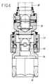
- the fitting of the shaft 30 in the extension 32 likewise as that of the extension 32 in the key 34 are of square section with sides parallel for the female parts and with square section in the shape of a barrel for the male parts, thus providing a patella effect.
- the key 34 further comprises, on the side of its free end, a conical inlet 36.
- Each clamping head 18 comprises a drive shaft 30 at the end of which is mounted a male-female extension 32 equipped with the quick release device 33 for a key 34.
- the machine being in the start position, advances one distance corresponding to the nominal distance between two crosspieces.
- the two groups of heads are moved vertically along the columns 45 until the keys 34 come to cover the bolts 7. If the positioning of the keys relative to the bolts is relatively satisfactory, i.e. if the key can come over the bolt despite a slight offset, the motors of the clamping heads 18 are put into operation. It then occurs, due to the "stiffening" of the joint obtained thanks to the crossed axes 35, a possible realignment drive shafts 30 which would be offset from the bolts correspondents. This realignment results in a displacement of the frames 14 carrying the two groups of clamping heads with respect to the chassis 8. This realignment is made possible by the springs 45 located on one side and due to the fact that the cylinder 48 located on the other side is in a position in which these two chambers communicate.
- the operator can act on the jack 48 to move the group 17 corresponding and bring it over the bolts 7.
- the other group of heads fall back into the clamping position thanks to the counter springs 45, as previously explained.
- the jack 48 brings back, by an electro-hydraulic automatism, the frame 14 corresponding to the central position.
- the operator has a remote control that allows it to change the position of the entire machine.
- the invention provides a great improvement to the existing technique by providing a machine allowing simultaneous tightening or loosening of four bolts, which is simple in structure and operation and extremely reliable.
Landscapes
- Engineering & Computer Science (AREA)
- Architecture (AREA)
- Civil Engineering (AREA)
- Structural Engineering (AREA)
- Mechanical Engineering (AREA)
- Machines For Laying And Maintaining Railways (AREA)
- Details Of Spanners, Wrenches, And Screw Drivers And Accessories (AREA)
- Clamps And Clips (AREA)
- Mutual Connection Of Rods And Tubes (AREA)
Abstract
Description
- un châssis équipé de galets prenant appui sur les deux rails de la voie ferrée et comportant un dispositif auto-moteur assurant son déplacement séquentiel d'une valeur correspondant à l'écartement nominal entre les traverses, sans patinage, ni glissement,
- deux groupes de deux têtes de vissage montés déplaçables verticalement à une extrémité du châssis, l'écartement des deux têtes d'un groupe pouvant être réglé, et chaque groupe étant monté avec possibilité de déplacement longitudinal sur le châssis, et chaque tête de vissage comprenant une clé montée de façon inclinable par rapport à l'axe de la tête, pour permettre son engagement sur un boulon en l'absence d'un alignement parfait entre la clé et le boulon.
Claims (12)
- Machine de vissage ou de dévissage de boulons (7) ou de tire-fond pour attaches (6) vissées de voies ferrées, comportant quatre têtes (18) destinées à actionner simultanément les quatre boulons ou les quatre tire-fond destinés à assurer la fixation d'un rail sur une traverse (3), caractérisée en ce qu'elle comprend :un châssis (8) équipé de galets (9) prenant appui sur les deux rails (4) de la voie ferrée et comportant un dispositif auto-moteur assurant son déplacement séquentiel d'une valeur correspondant à l'écartement nominal entre les traverses (3), sans patinage, ni glissement,deux groupes (17) de deux têtes de vissage (18) montés déplaçables verticalement à une extrémité du châssis (8), l'écartement des deux têtes (18) d'un groupe pouvant être réglé, et chaque groupe (17) étant monté avec possibilité de déplacement longitudinal sur le châssis, et chaque tête de vissage (18) comprenant une clé (34) montée de façon inclinable par rapport à l'axe de la tête (18), pour permettre son engagement sur un boulon (7) en l'absence d'un alignement parfait entre la clé et le boulon.
- Machine selon la revendication 1, caractérisée en ce que le châssis (8) comporte quatre galets (9) munis chacun d'un bandage réalisé en un matériau, par exemple à base de caoutchouc, évitant le patinage et le glissement, tous les quatre entraínés à partir d'un moteur thermique, un capteur constitué par un compteur d'impulsions (13) étant prévu à l'intérieur de la machine, qui arrête la machine lorsque celle-ci s'est déplacée d'une distance déterminée.
- Machine selon la revendication 2, caractérisée en ce que la valeur du déplacement de la machine entre deux cycles de serrage de boulons est réglable à l'aide d'une télécommande actionnable par l'opérateur.
- Machine selon l'une quelconque des revendications 1 à 3, caractérisée en ce que chaque tête de vissage (18) comprend une clé (34) dont l'ouverture présente une entrée conique (36) et est montée sur l'arbre d'entraínement correspondant par l'intermédiaire d'un dispositif (35) à rotule.
- Machine selon l'une quelconque des revendications 1 à 4, caractérisée en ce que chaque groupe (17) de deux têtes de vissage (18) est monté sur un bâti (14), lui-même monté coulissant longitudinalement sur le châssis (8) de la machine.
- Machine selon la revendication 5, caractérisée en ce qu'au moins un des groupes (17) de têtes de vissage (18) est maintenu auto-centré longitudinalement sous l'action de deux ressorts antagonistes (45) agissant chacun entre le châssis (8) de la machine et le bâti (14) porteur d'un groupe (17) de têtes de vissage (18).
- Machine selon la revendication 5, caractérisée en ce qu'au moins un des groupes (17) de têtes de vissage (18) est associé à un vérin hydraulique (48) monté entre le châssis (8) de la machine et le bâti (14) porteur d'un groupe de têtes de vissage, ce vérin (48) étant équipé d'un distributeur à centre ouvert le laissant libre en conditions normales d'utilisation de la machine, et pouvant commander l'alimentation en fluide hydraulique de l'une ou l'autre des deux chambres pour réaliser le positionnement longitudinal du groupe (17) de têtes de vissage (18), sur initiative de l'opérateur, si les têtes sont trop décalées par rapport aux écrous à serrer.
- Machine selon la revendication 7, caractérisée en ce que lorsque le vérin hydraulique (48) a été actionné pour réaliser le positionnement longitudinal d'un groupe (17) de têtes de vissage, le vérin est ramené par un automatisme électro-hydraulique en position centrale, en fin de vissage, lors de la remontée des têtes de vissage (18).
- Machine selon les revendications 6 à 8, caractérisée en ce qu'elle comporte, d'un côté, un groupe (17) de têtes de vissage (18) maintenu auto-centré à l'aide de ressorts (45) et, de l'autre côté, un groupe de têtes de vissage associé à un vérin hydraulique (48) de positionnement.
- Machine selon l'une des revendications 1 à 9, caractérisée en ce qu'elle comporte en outre un chariot (22), solidaire du châssis (8) de la machine et disposé en avant de celui-ci, équipé de moyens de positionnement avec précision, des traverses (3) sur lesquelles les rails doivent être fixés.
- Machine selon la revendication 10, caractérisée en ce que les moyens de positionnement des traverses sont constitués par des pinces et/ou des leviers (26) actionnés hydrauliquement permettant de pousser ou de tirer la traverse (3) située sous le chariot.
- Machine selon l'une des revendications 10 et 11, caractérisée en ce que le chariot (22) comporte des moyens (25) de bridage sur les rails, en période de positionnement d'une traverse.
Applications Claiming Priority (2)
| Application Number | Priority Date | Filing Date | Title |
|---|---|---|---|
| FR0013762A FR2815974B1 (fr) | 2000-10-26 | 2000-10-26 | Machine de vissage ou de devissage de boulons ou de tire-fond pour attaches vissees de voies ferrees |
| FR0013762 | 2000-10-26 |
Publications (2)
| Publication Number | Publication Date |
|---|---|
| EP1201826A1 true EP1201826A1 (fr) | 2002-05-02 |
| EP1201826B1 EP1201826B1 (fr) | 2004-05-26 |
Family
ID=8855775
Family Applications (1)
| Application Number | Title | Priority Date | Filing Date |
|---|---|---|---|
| EP01420213A Expired - Lifetime EP1201826B1 (fr) | 2000-10-26 | 2001-10-24 | Machine de vissage ou de dévissage de boulons ou de tire-fond pour attaches vissées de voies ferrées |
Country Status (4)
| Country | Link |
|---|---|
| EP (1) | EP1201826B1 (fr) |
| AT (1) | ATE267916T1 (fr) |
| DE (1) | DE60103475T2 (fr) |
| FR (1) | FR2815974B1 (fr) |
Cited By (17)
| Publication number | Priority date | Publication date | Assignee | Title |
|---|---|---|---|---|
| WO2007022965A1 (fr) * | 2005-08-25 | 2007-03-01 | Öbb-Infrastruktur Bau Aktiengesellschaft | Procede et vehicule combine destines au traitement de voies ferrees |
| RU2385377C1 (ru) * | 2009-01-11 | 2010-03-27 | Федеральное государственное унитарное предприятие Научно-внедренческий центр "Путевые машины" Федерального агентства железнодорожного транспорта | Устройство для завинчивания и отвинчивания гаек (шурупов) промежуточного рельсового скрепления железнодорожного пути |
| EP2233639A2 (fr) | 2009-03-27 | 2010-09-29 | Matisa Materiel Industriel S.A. | Dispositif d'installation de dispositifs de fixation de rails |
| EP3202980A1 (fr) * | 2016-02-04 | 2017-08-09 | Societe Turripinoise de Mecanique SA. | Procéde d'étalonnage d'une machine de serrage d'attaches vissées de rails d'une voie ferrée, notamment avec tirefonds ou écrous, système pour la mise en oeuvre du procéde et machine equipée d'un tel système |
| CN108677630A (zh) * | 2018-06-07 | 2018-10-19 | 中国铁建高新装备股份有限公司 | 一种铁路扣件养护作业小车 |
| ES2688770A1 (es) * | 2017-05-04 | 2018-11-06 | Universidad De Huelva | Dispositivo de roscado y desenroscado de conjuntos tornillo-tuerca |
| CN108797239A (zh) * | 2018-06-15 | 2018-11-13 | 山东交通学院 | 一种机器人及其铁路轨道的维护方法 |
| CN108857351A (zh) * | 2018-09-12 | 2018-11-23 | 北京好运达智创科技有限公司 | 轨枕套筒智能化锁付系统 |
| CN109352323A (zh) * | 2018-11-27 | 2019-02-19 | 武汉利德测控技术有限公司 | 一种扣件螺栓涂油紧固小车 |
| CN112025281A (zh) * | 2020-08-31 | 2020-12-04 | 龙铁纵横(北京)轨道交通科技股份有限公司 | 一种轨道扣件机器人自动化拧紧系统及方法 |
| JP2021092059A (ja) * | 2019-12-10 | 2021-06-17 | 西日本旅客鉄道株式会社 | まくらぎ補修用台車及び台車セット |
| CN113957757A (zh) * | 2021-11-16 | 2022-01-21 | 中国二十冶集团有限公司 | 轨道螺栓定位装置及轨道螺栓施工方法 |
| CN114198287A (zh) * | 2021-11-29 | 2022-03-18 | 吉林东光奥威汽车制动系统有限公司 | 一种电动真空泵泵室的装配装置 |
| CN114750269A (zh) * | 2022-02-17 | 2022-07-15 | 中铁上海工程局集团有限公司 | 铁路桥梁装配化墩帽自动化松锚穴孔系统 |
| CN115723086A (zh) * | 2021-08-30 | 2023-03-03 | 天泽电力(天津)有限公司 | 扳手装置及扳手装置的控制方法 |
| CN117107565A (zh) * | 2023-08-29 | 2023-11-24 | 株洲嘉成科技发展股份有限公司 | 一种自动化精调作业装置螺栓松紧时序控制方法 |
| CN117773550A (zh) * | 2023-12-29 | 2024-03-29 | 浙江海宁轨道交通运营管理有限公司 | 一种轨道螺栓自动紧固涂油装置 |
Families Citing this family (2)
| Publication number | Priority date | Publication date | Assignee | Title |
|---|---|---|---|---|
| DE102007053901B3 (de) * | 2007-11-09 | 2009-05-20 | Db Netz Ag | Vorrichtung zur Montage und Demontage eines Befestigungsmittels, insbesondere eines Schienenbefestigungsmittels auf einem Tragkörper |
| CN106312524B (zh) * | 2016-09-22 | 2017-12-29 | 珠海格力电器股份有限公司 | 长度可调节式管组件的辅助安装设备 |
Citations (5)
| Publication number | Priority date | Publication date | Assignee | Title |
|---|---|---|---|---|
| FR1206323A (fr) * | 1957-07-22 | 1960-02-09 | Materiel Ind S A Et Const Meca | Machine à tirefonner |
| US3628461A (en) * | 1968-10-25 | 1971-12-21 | Plasser Bahnbaumasch Franz | Machine for working on rail fastening elements |
| EP0169753A2 (fr) | 1984-07-27 | 1986-01-29 | Societe Turripinoise De Mecanique (S.A.R.L.) | Dispositif d'entraînement de l'arbre porte-clef d'une machine à tirefonner |
| FR2745216A1 (fr) | 1996-02-23 | 1997-08-29 | Turripinoise De Mecanique Sa S | Machine de vissage et de devissage de boulons ou de tire-fonds |
| JPH1161706A (ja) * | 1997-08-08 | 1999-03-05 | Akiyasu Takashima | レール固定用ボルトの自動締結装置 |
Family Cites Families (2)
| Publication number | Priority date | Publication date | Assignee | Title |
|---|---|---|---|---|
| IT8128959U1 (it) * | 1981-03-17 | 1982-09-17 | Utensileria Sassolese S A S Di Casanova Emilio Liverani Edgardo & C | Dispositivo autocentrante per l'accoppiamento degli utensili al mandrino di macchine utensili. |
| JP3844085B2 (ja) * | 1996-05-16 | 2006-11-08 | 株式会社小松製作所 | レール締結ボルトの締付機械及びそのボルト穴位置検出装置 |
-
2000
- 2000-10-26 FR FR0013762A patent/FR2815974B1/fr not_active Expired - Fee Related
-
2001
- 2001-10-24 AT AT01420213T patent/ATE267916T1/de not_active IP Right Cessation
- 2001-10-24 EP EP01420213A patent/EP1201826B1/fr not_active Expired - Lifetime
- 2001-10-24 DE DE60103475T patent/DE60103475T2/de not_active Expired - Fee Related
Patent Citations (5)
| Publication number | Priority date | Publication date | Assignee | Title |
|---|---|---|---|---|
| FR1206323A (fr) * | 1957-07-22 | 1960-02-09 | Materiel Ind S A Et Const Meca | Machine à tirefonner |
| US3628461A (en) * | 1968-10-25 | 1971-12-21 | Plasser Bahnbaumasch Franz | Machine for working on rail fastening elements |
| EP0169753A2 (fr) | 1984-07-27 | 1986-01-29 | Societe Turripinoise De Mecanique (S.A.R.L.) | Dispositif d'entraînement de l'arbre porte-clef d'une machine à tirefonner |
| FR2745216A1 (fr) | 1996-02-23 | 1997-08-29 | Turripinoise De Mecanique Sa S | Machine de vissage et de devissage de boulons ou de tire-fonds |
| JPH1161706A (ja) * | 1997-08-08 | 1999-03-05 | Akiyasu Takashima | レール固定用ボルトの自動締結装置 |
Non-Patent Citations (1)
| Title |
|---|
| PATENT ABSTRACTS OF JAPAN vol. 1999, no. 08 30 June 1999 (1999-06-30) * |
Cited By (23)
| Publication number | Priority date | Publication date | Assignee | Title |
|---|---|---|---|---|
| WO2007022965A1 (fr) * | 2005-08-25 | 2007-03-01 | Öbb-Infrastruktur Bau Aktiengesellschaft | Procede et vehicule combine destines au traitement de voies ferrees |
| RU2385377C1 (ru) * | 2009-01-11 | 2010-03-27 | Федеральное государственное унитарное предприятие Научно-внедренческий центр "Путевые машины" Федерального агентства железнодорожного транспорта | Устройство для завинчивания и отвинчивания гаек (шурупов) промежуточного рельсового скрепления железнодорожного пути |
| EP2233639A2 (fr) | 2009-03-27 | 2010-09-29 | Matisa Materiel Industriel S.A. | Dispositif d'installation de dispositifs de fixation de rails |
| EP3202980A1 (fr) * | 2016-02-04 | 2017-08-09 | Societe Turripinoise de Mecanique SA. | Procéde d'étalonnage d'une machine de serrage d'attaches vissées de rails d'une voie ferrée, notamment avec tirefonds ou écrous, système pour la mise en oeuvre du procéde et machine equipée d'un tel système |
| FR3047493A1 (fr) * | 2016-02-04 | 2017-08-11 | Soc Turripinoise De Mec | Procede d'etalonnage d'une machine de serrage d'attaches vissees de rails d'une voie ferree, notamment avec tirefonds ou ecrous, systeme pour la mise en œuvre du procede et machine equipee d'un tel systeme |
| ES2688770A1 (es) * | 2017-05-04 | 2018-11-06 | Universidad De Huelva | Dispositivo de roscado y desenroscado de conjuntos tornillo-tuerca |
| CN108677630A (zh) * | 2018-06-07 | 2018-10-19 | 中国铁建高新装备股份有限公司 | 一种铁路扣件养护作业小车 |
| CN108677630B (zh) * | 2018-06-07 | 2023-11-07 | 中国铁建高新装备股份有限公司 | 一种铁路扣件养护作业小车 |
| CN108797239A (zh) * | 2018-06-15 | 2018-11-13 | 山东交通学院 | 一种机器人及其铁路轨道的维护方法 |
| CN108857351B (zh) * | 2018-09-12 | 2023-10-13 | 北京好运达智创科技有限公司 | 轨枕套筒智能化锁付系统 |
| CN108857351A (zh) * | 2018-09-12 | 2018-11-23 | 北京好运达智创科技有限公司 | 轨枕套筒智能化锁付系统 |
| CN109352323A (zh) * | 2018-11-27 | 2019-02-19 | 武汉利德测控技术有限公司 | 一种扣件螺栓涂油紧固小车 |
| CN109352323B (zh) * | 2018-11-27 | 2023-12-05 | 武汉利德测控技术有限公司 | 一种扣件螺栓涂油紧固小车 |
| JP2021092059A (ja) * | 2019-12-10 | 2021-06-17 | 西日本旅客鉄道株式会社 | まくらぎ補修用台車及び台車セット |
| CN112025281A (zh) * | 2020-08-31 | 2020-12-04 | 龙铁纵横(北京)轨道交通科技股份有限公司 | 一种轨道扣件机器人自动化拧紧系统及方法 |
| CN112025281B (zh) * | 2020-08-31 | 2022-06-07 | 龙铁纵横(北京)轨道交通科技股份有限公司 | 一种轨道扣件机器人自动化拧紧系统及方法 |
| CN115723086A (zh) * | 2021-08-30 | 2023-03-03 | 天泽电力(天津)有限公司 | 扳手装置及扳手装置的控制方法 |
| CN113957757A (zh) * | 2021-11-16 | 2022-01-21 | 中国二十冶集团有限公司 | 轨道螺栓定位装置及轨道螺栓施工方法 |
| CN114198287A (zh) * | 2021-11-29 | 2022-03-18 | 吉林东光奥威汽车制动系统有限公司 | 一种电动真空泵泵室的装配装置 |
| CN114198287B (zh) * | 2021-11-29 | 2024-05-17 | 吉林东光奥威汽车制动系统有限公司 | 一种电动真空泵泵室的装配装置 |
| CN114750269A (zh) * | 2022-02-17 | 2022-07-15 | 中铁上海工程局集团有限公司 | 铁路桥梁装配化墩帽自动化松锚穴孔系统 |
| CN117107565A (zh) * | 2023-08-29 | 2023-11-24 | 株洲嘉成科技发展股份有限公司 | 一种自动化精调作业装置螺栓松紧时序控制方法 |
| CN117773550A (zh) * | 2023-12-29 | 2024-03-29 | 浙江海宁轨道交通运营管理有限公司 | 一种轨道螺栓自动紧固涂油装置 |
Also Published As
| Publication number | Publication date |
|---|---|
| DE60103475D1 (de) | 2004-07-01 |
| EP1201826B1 (fr) | 2004-05-26 |
| FR2815974B1 (fr) | 2004-07-09 |
| DE60103475T2 (de) | 2004-09-16 |
| ATE267916T1 (de) | 2004-06-15 |
| FR2815974A1 (fr) | 2002-05-03 |
Similar Documents
| Publication | Publication Date | Title |
|---|---|---|
| EP1201826B1 (fr) | Machine de vissage ou de dévissage de boulons ou de tire-fond pour attaches vissées de voies ferrées | |
| CA1151710A (fr) | Procede et dispositif pour le freinage d'un aeronef par recherche d'un glissement optimal des roues freinees | |
| FR2992304A1 (fr) | Dispositif et procede pour le blocage d'un vehicule et station de chargement-dechargement dotee de celui-ci | |
| FR2503065A1 (fr) | Dispositif destine a equiper un marbre de controle et/ou de reparation de carrosseries de voitures automobiles | |
| EP2822842B1 (fr) | Remorque routière à train de roulage secondaire orientable | |
| CA1177695A (fr) | Systeme de guidage automatique d'un vehicule muni de roues a bandage pneumatique | |
| CA1302070C (fr) | Machine de traction pour le dressage et la relaxation des contraintes desrails en acier | |
| FR2560351A1 (fr) | Machine a marche automatique conduite a la main | |
| EP0633175B1 (fr) | Train amovible pour le roulage directif d'une charge | |
| WO2012020175A1 (fr) | Banc d'essais a rouleau pour vehicules a moteur | |
| FR2935128A1 (fr) | Procede d'autopilotage de transmission et dispositif de transmission autopilotable pour vehicules remorques, en particulier pour machines a vendanger tractees, attelables a un vehicule auto propulseur | |
| FR2889510A1 (fr) | Procede de groupage de caisses sur un convoyeur et dispositif pour sa mise en oeuvre | |
| EP0968905A1 (fr) | Train de véhicule de transport, du type train suiveur de tunnelier | |
| FR3021284A1 (fr) | Engin polyvalent de travaux de maintenance de voie ferree. | |
| LU500456A1 (fr) | Dispositif de détection d'inclinaison de murs pour la Restauration de bâtiments anciens en Pierre | |
| CH660442A5 (fr) | Mecanisme d'inversion d'une charrue semi-reversible. | |
| FR2539208A1 (fr) | Dispositif de securite pour perceuses sensitives | |
| FR2911700A1 (fr) | Dispositif destine a la conduite d'un vehicule par des personnes handicapees | |
| FR2683696A1 (fr) | Pulverisateur en v a commande de repliement hydraulique des trains de disques. | |
| FR2682135A1 (fr) | Machine pour le vissage et le devissage automatiques de rails poses sur des traverses. | |
| FR2758228A1 (fr) | Machine agricole, en particulier de preparation du sol et de dechaumage comportant des moyens d'entrainement en pivotement des trains porteurs d'outils | |
| FR2562573A1 (fr) | Dispositif de levage de voie ferree | |
| FR2666358A1 (fr) | Procede et machine de traitement de voie ferree. | |
| FR2465030A1 (fr) | Machine de positionnement de traverses sur le ballast d'une voie ferree | |
| FR2549892A1 (fr) | Machine pour appliquer un couple de vissage ou de devissage a des tiges, en particulier des tiges de forage |
Legal Events
| Date | Code | Title | Description |
|---|---|---|---|
| PUAI | Public reference made under article 153(3) epc to a published international application that has entered the european phase |
Free format text: ORIGINAL CODE: 0009012 |
|
| AK | Designated contracting states |
Kind code of ref document: A1 Designated state(s): AT BE CH CY DE DK ES FI FR GB GR IE IT LI LU MC NL PT SE TR |
|
| AX | Request for extension of the european patent |
Free format text: AL;LT;LV;MK;RO;SI |
|
| 17P | Request for examination filed |
Effective date: 20020521 |
|
| 17Q | First examination report despatched |
Effective date: 20020722 |
|
| AKX | Designation fees paid |
Free format text: AT BE CH CY DE DK ES FI FR GB GR IE IT LI LU MC NL PT SE TR |
|
| GRAH | Despatch of communication of intention to grant a patent |
Free format text: ORIGINAL CODE: EPIDOS IGRA |
|
| GRAS | Grant fee paid |
Free format text: ORIGINAL CODE: EPIDOSNIGR3 |
|
| GRAA | (expected) grant |
Free format text: ORIGINAL CODE: 0009210 |
|
| AK | Designated contracting states |
Kind code of ref document: B1 Designated state(s): AT BE CH CY DE DK ES FI FR GB GR IE IT LI LU MC NL PT SE TR |
|
| PG25 | Lapsed in a contracting state [announced via postgrant information from national office to epo] |
Ref country code: TR Free format text: LAPSE BECAUSE OF FAILURE TO SUBMIT A TRANSLATION OF THE DESCRIPTION OR TO PAY THE FEE WITHIN THE PRESCRIBED TIME-LIMIT Effective date: 20040526 Ref country code: NL Free format text: LAPSE BECAUSE OF FAILURE TO SUBMIT A TRANSLATION OF THE DESCRIPTION OR TO PAY THE FEE WITHIN THE PRESCRIBED TIME-LIMIT Effective date: 20040526 Ref country code: IT Free format text: LAPSE BECAUSE OF FAILURE TO SUBMIT A TRANSLATION OF THE DESCRIPTION OR TO PAY THE FEE WITHIN THE PRESCRIBED TIME-LIMIT;WARNING: LAPSES OF ITALIAN PATENTS WITH EFFECTIVE DATE BEFORE 2007 MAY HAVE OCCURRED AT ANY TIME BEFORE 2007. THE CORRECT EFFECTIVE DATE MAY BE DIFFERENT FROM THE ONE RECORDED. Effective date: 20040526 Ref country code: IE Free format text: LAPSE BECAUSE OF FAILURE TO SUBMIT A TRANSLATION OF THE DESCRIPTION OR TO PAY THE FEE WITHIN THE PRESCRIBED TIME-LIMIT Effective date: 20040526 Ref country code: GB Free format text: LAPSE BECAUSE OF FAILURE TO SUBMIT A TRANSLATION OF THE DESCRIPTION OR TO PAY THE FEE WITHIN THE PRESCRIBED TIME-LIMIT Effective date: 20040526 Ref country code: FI Free format text: LAPSE BECAUSE OF FAILURE TO SUBMIT A TRANSLATION OF THE DESCRIPTION OR TO PAY THE FEE WITHIN THE PRESCRIBED TIME-LIMIT Effective date: 20040526 Ref country code: CY Free format text: LAPSE BECAUSE OF FAILURE TO SUBMIT A TRANSLATION OF THE DESCRIPTION OR TO PAY THE FEE WITHIN THE PRESCRIBED TIME-LIMIT Effective date: 20040526 Ref country code: AT Free format text: LAPSE BECAUSE OF FAILURE TO SUBMIT A TRANSLATION OF THE DESCRIPTION OR TO PAY THE FEE WITHIN THE PRESCRIBED TIME-LIMIT Effective date: 20040526 |
|
| REG | Reference to a national code |
Ref country code: GB Ref legal event code: FG4D Free format text: NOT ENGLISH |
|
| REG | Reference to a national code |
Ref country code: CH Ref legal event code: EP |
|
| REG | Reference to a national code |
Ref country code: IE Ref legal event code: FG4D Free format text: FRENCH |
|
| REF | Corresponds to: |
Ref document number: 60103475 Country of ref document: DE Date of ref document: 20040701 Kind code of ref document: P |
|
| PG25 | Lapsed in a contracting state [announced via postgrant information from national office to epo] |
Ref country code: SE Free format text: LAPSE BECAUSE OF FAILURE TO SUBMIT A TRANSLATION OF THE DESCRIPTION OR TO PAY THE FEE WITHIN THE PRESCRIBED TIME-LIMIT Effective date: 20040826 Ref country code: GR Free format text: LAPSE BECAUSE OF FAILURE TO SUBMIT A TRANSLATION OF THE DESCRIPTION OR TO PAY THE FEE WITHIN THE PRESCRIBED TIME-LIMIT Effective date: 20040826 Ref country code: DK Free format text: LAPSE BECAUSE OF FAILURE TO SUBMIT A TRANSLATION OF THE DESCRIPTION OR TO PAY THE FEE WITHIN THE PRESCRIBED TIME-LIMIT Effective date: 20040826 |
|
| PG25 | Lapsed in a contracting state [announced via postgrant information from national office to epo] |
Ref country code: ES Free format text: LAPSE BECAUSE OF FAILURE TO SUBMIT A TRANSLATION OF THE DESCRIPTION OR TO PAY THE FEE WITHIN THE PRESCRIBED TIME-LIMIT Effective date: 20040906 |
|
| PG25 | Lapsed in a contracting state [announced via postgrant information from national office to epo] |
Ref country code: LU Free format text: LAPSE BECAUSE OF NON-PAYMENT OF DUE FEES Effective date: 20041024 |
|
| PG25 | Lapsed in a contracting state [announced via postgrant information from national office to epo] |
Ref country code: MC Free format text: LAPSE BECAUSE OF NON-PAYMENT OF DUE FEES Effective date: 20041031 Ref country code: BE Free format text: LAPSE BECAUSE OF NON-PAYMENT OF DUE FEES Effective date: 20041031 |
|
| GBV | Gb: ep patent (uk) treated as always having been void in accordance with gb section 77(7)/1977 [no translation filed] |
Effective date: 20040526 |
|
| REG | Reference to a national code |
Ref country code: FR Ref legal event code: CL |
|
| NLV1 | Nl: lapsed or annulled due to failure to fulfill the requirements of art. 29p and 29m of the patents act | ||
| REG | Reference to a national code |
Ref country code: IE Ref legal event code: FD4D |
|
| PLBE | No opposition filed within time limit |
Free format text: ORIGINAL CODE: 0009261 |
|
| STAA | Information on the status of an ep patent application or granted ep patent |
Free format text: STATUS: NO OPPOSITION FILED WITHIN TIME LIMIT |
|
| BERE | Be: lapsed |
Owner name: SOC. TURRIPINOISE DE MECANIQUE SA Effective date: 20041031 |
|
| 26N | No opposition filed |
Effective date: 20050301 |
|
| PG25 | Lapsed in a contracting state [announced via postgrant information from national office to epo] |
Ref country code: LI Free format text: LAPSE BECAUSE OF NON-PAYMENT OF DUE FEES Effective date: 20051031 Ref country code: CH Free format text: LAPSE BECAUSE OF NON-PAYMENT OF DUE FEES Effective date: 20051031 |
|
| REG | Reference to a national code |
Ref country code: CH Ref legal event code: PL |
|
| PGFP | Annual fee paid to national office [announced via postgrant information from national office to epo] |
Ref country code: FR Payment date: 20060925 Year of fee payment: 6 |
|
| PGFP | Annual fee paid to national office [announced via postgrant information from national office to epo] |
Ref country code: DE Payment date: 20061009 Year of fee payment: 6 |
|
| BERE | Be: lapsed |
Owner name: SOC. TURRIPINOISE DE *MECANIQUE S.A. Effective date: 20041031 |
|
| PG25 | Lapsed in a contracting state [announced via postgrant information from national office to epo] |
Ref country code: PT Free format text: LAPSE BECAUSE OF NON-PAYMENT OF DUE FEES Effective date: 20041026 |
|
| PG25 | Lapsed in a contracting state [announced via postgrant information from national office to epo] |
Ref country code: DE Free format text: LAPSE BECAUSE OF NON-PAYMENT OF DUE FEES Effective date: 20080501 |
|
| REG | Reference to a national code |
Ref country code: FR Ref legal event code: ST Effective date: 20080630 |
|
| PG25 | Lapsed in a contracting state [announced via postgrant information from national office to epo] |
Ref country code: FR Free format text: LAPSE BECAUSE OF NON-PAYMENT OF DUE FEES Effective date: 20071031 |