EP1201942A1 - Befestigungsmittel für längliche Gegenstände - Google Patents
Befestigungsmittel für längliche Gegenstände Download PDFInfo
- Publication number
- EP1201942A1 EP1201942A1 EP01811003A EP01811003A EP1201942A1 EP 1201942 A1 EP1201942 A1 EP 1201942A1 EP 01811003 A EP01811003 A EP 01811003A EP 01811003 A EP01811003 A EP 01811003A EP 1201942 A1 EP1201942 A1 EP 1201942A1
- Authority
- EP
- European Patent Office
- Prior art keywords
- gripping elements
- fastening device
- anchoring unit
- receiving part
- anchoring
- Prior art date
- Legal status (The legal status is an assumption and is not a legal conclusion. Google has not performed a legal analysis and makes no representation as to the accuracy of the status listed.)
- Granted
Links
- 238000004873 anchoring Methods 0.000 claims abstract description 38
- 230000005540 biological transmission Effects 0.000 claims description 5
- 238000003780 insertion Methods 0.000 description 5
- 230000037431 insertion Effects 0.000 description 5
- 238000004519 manufacturing process Methods 0.000 description 2
- 229910000639 Spring steel Inorganic materials 0.000 description 1
- 230000000295 complement effect Effects 0.000 description 1
- 238000010276 construction Methods 0.000 description 1
- 238000009434 installation Methods 0.000 description 1
- 239000000463 material Substances 0.000 description 1
- 230000008092 positive effect Effects 0.000 description 1
Images


Classifications
-
- F—MECHANICAL ENGINEERING; LIGHTING; HEATING; WEAPONS; BLASTING
- F16—ENGINEERING ELEMENTS AND UNITS; GENERAL MEASURES FOR PRODUCING AND MAINTAINING EFFECTIVE FUNCTIONING OF MACHINES OR INSTALLATIONS; THERMAL INSULATION IN GENERAL
- F16B—DEVICES FOR FASTENING OR SECURING CONSTRUCTIONAL ELEMENTS OR MACHINE PARTS TOGETHER, e.g. NAILS, BOLTS, CIRCLIPS, CLAMPS, CLIPS OR WEDGES; JOINTS OR JOINTING
- F16B37/00—Nuts or like thread-engaging members
- F16B37/04—Devices for fastening nuts to surfaces, e.g. sheets, plates
- F16B37/045—Devices for fastening nuts to surfaces, e.g. sheets, plates specially adapted for fastening in channels, e.g. sliding bolts, channel nuts
- F16B37/046—Devices for fastening nuts to surfaces, e.g. sheets, plates specially adapted for fastening in channels, e.g. sliding bolts, channel nuts with resilient means for urging the nut inside the channel
-
- F—MECHANICAL ENGINEERING; LIGHTING; HEATING; WEAPONS; BLASTING
- F16—ENGINEERING ELEMENTS AND UNITS; GENERAL MEASURES FOR PRODUCING AND MAINTAINING EFFECTIVE FUNCTIONING OF MACHINES OR INSTALLATIONS; THERMAL INSULATION IN GENERAL
- F16B—DEVICES FOR FASTENING OR SECURING CONSTRUCTIONAL ELEMENTS OR MACHINE PARTS TOGETHER, e.g. NAILS, BOLTS, CIRCLIPS, CLAMPS, CLIPS OR WEDGES; JOINTS OR JOINTING
- F16B7/00—Connections of rods or tubes, e.g. of non-circular section, mutually, including resilient connections
- F16B7/04—Clamping or clipping connections
- F16B7/044—Clamping or clipping connections for rods or tubes being in angled relationship
- F16B7/0446—Clamping or clipping connections for rods or tubes being in angled relationship for tubes using the innerside thereof
- F16B7/0473—Clamping or clipping connections for rods or tubes being in angled relationship for tubes using the innerside thereof with hook-like parts gripping, e.g. by expanding, behind the flanges of a profile
Definitions
- the invention relates to a fastening device with at least two mutually movable, Anchoring unit having mutually prestressed gripping elements and a mounting rail with a mounting opening, which is on both sides of longitudinal walls is limited, which have on their mutually facing inside holding projections in a snap-in position at least partially from the corresponding gripping elements of the Anchoring unit can be gripped transversely to the longitudinal direction of the mounting rail, wherein the anchoring unit is connected by means of a bolt.
- Fastening devices of the type mentioned above are used to fasten objects for example on a surface, using a mounting rail.
- a mounting rail For example, serves the fastening device for hanging objects such as pipes or the like.
- EP-B1-671581 is a fastening device of the type mentioned known, which has a gripping element engaging behind the holding projections.
- the gripping element has two mutually elastically resilient support parts, the corresponding ones Reach behind the protrusions.
- the gripping element is connected to a by means of a bolt the free longitudinal edges of the mounting rail acting stop connected. By clamping the gripping element with the stop, the retaining projections are on the bolt clamped.
- the advantage of the known solution is that the support part is in a pre-assembly position snaps into the mounting rail and thus prevents the anchoring unit from falling out. This feature proves to be extremely important, particularly in the case of overhead installation advantageous.
- a disadvantage of the known solution is that the gripping element is unstable. On the one hand leads this fact leads to insufficient guidance of the anchoring part when inserting it into the mounting rail and on the other hand this results in low load values for the fastening device all in all.
- the present invention has for its object to provide a fastening device creating gripping elements that have high load values and are simple Handling allowed.
- the manufacture of the fastening device should be economical his.
- the anchoring unit is a receiving part with openings for guiding the gripping elements.
- the receiving part is provided with openings, the gripping elements, which engage behind the retaining projections, optimally guided.
- the anchoring unit ensures thus significantly higher holding values, even with dynamic loading of the fastening device.
- the receiving part has at least two longitudinally extending Anchoring walls, each with at least two support points in the locked position have the corresponding holding projection in order to twist the receiving part, in particular to prevent the anchoring unit relative to the mounting rail.
- the a total of at least four support points are essentially with the holding projections in contact.
- the support points represent an insertion of the anchoring unit into the Mounting opening in a predetermined position relative to the retaining projections.
- the anchoring walls preferably run parallel to the holding projections and in in the snap-in position, they essentially rest on them. On the one hand, this is the one for leadership area of the anchoring unit is maximized and on the other hand a force distribution optimally distributed to the anchoring unit in the case of obliquely acting forces.
- the receiving part is U-shaped and the Anchoring walls form the free legs of the receiving part, around which the fastening device force acting evenly by means of a load by means of the gripping elements forward the mounting rails.
- this training of the receiving part promotes an economical production and easy assembly of the fastening device.
- the gripping elements are advantageously L-shaped and have on the engaging behind the retaining projections opposite end on a web, which in a complementary recess can be brought to the receiving part.
- This simple construction has a positive effect on the Economic efficiency of the fastening device.
- others can too Find solutions for storing the gripping elements.
- the Gripping elements can be formed in one piece from spring steel.
- a gripping element advantageously has 2 to 3 individual gripping fingers, which engage behind the holding projections.
- two gripping elements intersect in one Axis of rotation, the gripping elements being rotatably connected to one another in the axis of rotation and in the locked position by a torsion spring mounted on the axis of rotation in the direction Retaining protrusions are biased against each other.
- the arrangement of the gripping elements has an impact, for example. This causes a particularly high stability.
- the gripping elements preferably have, at least on the one that engages behind the holding projections End area, a V-shaped cross-section to with little material and high weight savings to achieve optimal stability of the gripping elements. Furthermore point the gripping elements at the end region engaging behind the holding projections an insertion ramp to make it easy to snap in when inserting the anchoring unit ensure the gripping elements. The gripping elements slide along the insertion Ramps against each other and only in a position behind the retaining projections snap them up.
- the anchoring unit advantageously has one of the free longitudinal edges of the mounting rail loading stop. Especially if an object to be fastened cannot perform this function, for example because it has the necessary functions does not have geometric dimensions, a stop is necessary.
- the attack can for example, be plate-shaped and partially protrude beyond the mounting opening.
- the bolt preferably has an external thread at least partially over its longitudinal extent and at the end facing away from the anchoring unit, a torque transmission device on, which at least partially projects radially beyond the bolt.
- a torque transmission device on, which at least partially projects radially beyond the bolt.
- a polygonal screw head for example, can be used as the torque transmission device Find application.
- the object to be fastened can, for example have a through hole that is approximately the outer diameter of the bolt equivalent. The at least partially radially projecting the bolt torque transmission device ensures that the object is pressed against the mounting rail.
- the receiving part advantageously has an internal thread for connecting the anchoring unit with the bolt to ensure economical and handy fastening.
- a fastening device is in a not introduced Position with one, at least two mutually movable, biased against each other Gripping elements 9, anchoring unit 1 and a mounting rail 2 shown.
- the mounting rail 2 has a mounting opening 3, which on both sides of Longitudinal walls 4 is limited.
- the longitudinal walls 4 face one another Inside holding projections 5, which are in a locked position E, as shown in particular in Fig. 2 is shown, at least partially by the corresponding gripping elements 9 of the Anchoring unit 1 can be gripped behind transversely to the longitudinal direction L of the mounting rail 2.
- the anchoring unit 1 has for attaching an object, not shown a bolt 7 with an external thread 7a, the one with a receiving part 10, the several Has openings 14 for guiding the gripping elements 9 is connected.
- the recording part 10 has a U-shaped cross section, with the free legs through two anchoring walls 11 are formed, which run parallel to the holding projections 5 and in the snap-in position E essentially rest on them.
- the gripping elements 9 are L-shaped, preferably with 2 to 3 gripping fingers 9a and connected to each other by a U-shaped spring clip 12, as in particular 1 and 2 emerge.
- the gripping elements 9 each have an insertion ramp 13.
- the Cross-section of the gripping elements 9 in the area of the gripping fingers 9a is V-shaped, like this 3 emerges in particular.
- the V-shaped design causes stiffening the gripping elements 9, in particular the gripping fingers 9a and on the other hand Known, which with a, arranged on the holding projections 5, counter teeth 16 combine
- FIG. 4 and 5 show a further embodiment of a fastening device according to the invention with a mounting rail 20, the holding projections 21 of gripping elements 22 can be engaged in a snap-in position E.
- 4 shows in particular the use of the fastening device according to the invention as a rail bracket.
- two anchoring units 23 and 24 are connected to one another by an angle element 25.
- a receiving part 26 guides the L-shaped gripping elements 22 through a spring element 27 are biased against each other, as can be seen in particular from FIG. 5.
- the Gripping elements 22 reach through the receiving part 26 in openings 28 and by means of webs 30 in Recesses 29. As a result, the gripping elements 22 are articulated with the receiving part 26 connected.
- the same also shows on the side facing the angle element 25 Internal thread 31 on.
- the angle element 25 has a through bore 32 for receiving a bolt 33 with a screw head 34 and an external thread.
- the screw head 34 protrudes the bolt 33 radially and serves as a torque transmission device for the final Attach the fastening device according to the invention.
- For pre-fixation is between the screw head 34 and the angle element 25 are arranged a spring element 34a
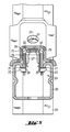
- FIG. 6 to 8 show a further embodiment of the fastening device according to the invention with a receiving part 35 and two by the arranged on the receiving part 35 Openings 36 guided gripping elements 37.
- the two gripping elements 37 cross itself in an axis of rotation 38, the gripping elements 37 being rotatable with one another in the axis of rotation 38 are connected and by a torsion spring 39 mounted on the axis of rotation 38 in Are biased towards each other, as shown in particular in Fig. 7 is shown.
- FIG. 8 shows a gripping element 37 with one arranged on the rear-engaging end regions Toothing 41.
- the toothing 41 comes in the snap-in position E with the engaging behind Retaining projection 40 in contact and thus increases the load value of the fastening device, since the friction between the holding projection 40 and the gripping element 37 increases, in particular if the holding projections 40 have counter teeth.
- center the gripping elements 37 have a through bore 42 which is provided by one on the receiving part 35 fastened bolt 43 for guiding the gripping elements 37 is penetrated.
Landscapes
- Engineering & Computer Science (AREA)
- General Engineering & Computer Science (AREA)
- Mechanical Engineering (AREA)
- Clamps And Clips (AREA)
- Supports For Plants (AREA)
Abstract
Description
- Fig. 1
- Eine erste Ausführungsform einer erfindungsgemässen Befestigungsvorrichtung im Querschnitt in einer nicht eingeführten Position;
- Fig. 2
- die in Fig. 1 dargestellte Befestigungsvorrichtung in der eingeführten Position;
- Fig. 3
- eine Längsansicht der in Fig.1 und 2 dargestellten Befestigungsvorrichtung;
- Fig. 4
- eine weitere Ausführungsform der erfindungsgemässen Befestigungsvorrichtung als Winkelverbinder für zwei Montageschienen;
- Fig. 5
- die in Fig. 4 dargestellte Ausführungsform um 90° gedreht;
- Fig. 6
- eine weitere Ausführungsform mit gekreuzten Greifelementen in einer nicht eingeführten Position;
- Fig. 7
- die in Fig. 6 dargestellte Ausführungsform in der eingeführten Position;
- Fig. 8
- ein Greifelement der n Fig. 6 und 7 dargestellten Ausführungsform.
Claims (10)
- Befestigungsvorrichtung mit einer, zumindest zwei zueinander bewegbare, gegeneinander vorgespannte Greifelemente (9, 22, 37) aufweisenden, Verankerungseinheit (1) und einer Montageschiene (2, 20) mit einer Montageöffnung (3), welche beidseits von Längswänden (4) begrenzt ist, die an ihrer einander zugewandten Innenseite Haltevorsprünge (5, 21, 40) aufweisen, die in einer Einraststellung (E) zumindest teilweise von den entsprechenden Greifelementen (9, 22, 37) der Verankerungseinheit (1) quer zur Längsrichtung (L) der Montageschiene hintergriffen werden, wobei die Verankerungseinheit (1) mittels einem Bolzen (7, 33) verbunden ist, dadurch gekennzeichnet, dass die Verankerungseinheit (1) ein Aufnahmeteil (10, 26, 35) mit Öffnungen (14, 28, 36) zur Führung der Greifelemente (9, 22, 37) aufweist.
- Befestigungsvorrichtung nach Anspruch 1, dadurch gekennzeichnet, dass das Aufnahmeteil (10, 26, 35) zumindest zwei, in Längsrichtung (L) verlaufende, Verankerungswände (11) aufweist, die in der Einraststellung (E) jeweils zumindest zwei Auflagepunkte mit dem korrespondierenden Haltevorsprung (5, 21, 40) aufweisen.
- Befestigungsvorrichtung nach Anspruch 2, dadurch gekennzeichnet, dass die Verankerungswände (11) parallel zu den Haltevorsprüngen (5, 21, 40) verlaufen und in der Einraststellung (E) an diesen im wesentlichen anliegen.
- Befestigungselement nach einem der Ansprüche 1 bis 3, dadurch gekennzeichnet, dass das Aufnahmeteil (10, 26, 35) U-förmig ausgebildet ist und die Verankerungswände (11) die freien Schenkel des Aufnahmeteils (10, 26, 35) bilden.
- Befestigungselement nach einem der Ansprüche 1 bis 4, dadurch gekennzeichnet, dass die Greifelemente (22) L-förmig ausgebildet sind und an dem die Haltevorsprünge (21) hintergreifenden gegenüberliegenden Ende einen Steg (30) aufweisen, der in eine komplementär ausgebildete Ausnehmung (29) am Aufnahmeteil (26) bringbar ist.
- Befestigungselement nach einem der Ansprüche 1 bis 5, dadurch gekennzeichnet, dass zwei Greifelemente (37) sich in einer Drehachse (43) kreuzen, wobei die Greifelemente (37) in der Drehachse (43) drehbar miteinander verbunden sind und in der Einraststellung (E) durch eine an der Drehachse (43) gelagerte Torsionsfeder (39) in Richtung Haltevorsprünge (40) gegeneinander vorgespannt werden.
- Befestigungsvorrichtung nach einem der Ansprüche 1 bis 6, dadurch gekennzeichnet, dass die Greifelemente (9, 37) zumindest an dem die Haltevorsprünge (5, 40) hintergreifenden Endbereich einen V-förmigen Querschnitt aufweisen.
- Befestigungsvorrichtung nach einem der Ansprüche 1 bis 7, dadurch gekennzeichnet, dass die Verankerungseinheit (1) einen die freien Längsränder der Montageschiene (2) beaufschlagenden Anschlag aufweist.
- Befestigungsvorrichtung nach einem der Ansprüche 1 bis 8, dadurch gekennzeichnet, dass der Bolzen (7) zumindest teilweise über seine Längserstreckung ein Aussengewinde (7a) und an dem der Verankerungseinheit (1) abgewandten Ende eine Drehübertragungsvorrichtung (34) aufweist, die den Bolzen (7) zumindest teilweise radial überragt.
- Befestigungsvorrichtung nach Anspruch 9, dadurch gekennzeichnet, dass das Aufnahmeteil (10) ein Innengewinde (18) zur Verbindung der Verankerungseinheit (1) mit dem Bolzen (7, 33) aufweist.
Applications Claiming Priority (2)
| Application Number | Priority Date | Filing Date | Title |
|---|---|---|---|
| DE10052547 | 2000-10-23 | ||
| DE10052547A DE10052547A1 (de) | 2000-10-23 | 2000-10-23 | Befestigungsmittel für längliche Gegenstände |
Publications (2)
| Publication Number | Publication Date |
|---|---|
| EP1201942A1 true EP1201942A1 (de) | 2002-05-02 |
| EP1201942B1 EP1201942B1 (de) | 2007-02-28 |
Family
ID=7660783
Family Applications (1)
| Application Number | Title | Priority Date | Filing Date |
|---|---|---|---|
| EP01811003A Expired - Lifetime EP1201942B1 (de) | 2000-10-23 | 2001-10-15 | Befestigungsmittel für längliche Gegenstände |
Country Status (5)
| Country | Link |
|---|---|
| US (1) | US20020048497A1 (de) |
| EP (1) | EP1201942B1 (de) |
| AT (1) | ATE355466T1 (de) |
| DE (2) | DE10052547A1 (de) |
| ES (1) | ES2281404T3 (de) |
Cited By (1)
| Publication number | Priority date | Publication date | Assignee | Title |
|---|---|---|---|---|
| DE10236075A1 (de) * | 2002-08-07 | 2004-02-19 | Adam Opel Ag | Lösbare Befestigungsanordnung für Funktionselemente |
Families Citing this family (5)
| Publication number | Priority date | Publication date | Assignee | Title |
|---|---|---|---|---|
| DE10256861A1 (de) * | 2002-12-05 | 2004-06-24 | Hilti Ag | Befestigungssystem |
| DE102004009935A1 (de) * | 2004-02-26 | 2005-09-15 | Müller, Franz | Verfahren und System zur Befestigung von Plattenelementen |
| CN103790903B (zh) * | 2014-01-22 | 2016-03-30 | 湖南省金为型材有限公司 | 护栏 |
| CN109537721B (zh) * | 2018-12-07 | 2025-07-25 | 福建省德牧卫浴科技有限公司 | 一种连接结构和框架 |
| DE102019202993A1 (de) | 2019-03-06 | 2020-09-10 | Robert Bosch Gmbh | Verbinder mit über einen Hebelarm verbundenen Greifelementen |
Citations (4)
| Publication number | Priority date | Publication date | Assignee | Title |
|---|---|---|---|---|
| US4146074A (en) * | 1977-10-07 | 1979-03-27 | B-Line Systems, Inc. | Fastener |
| US4285379A (en) * | 1979-09-17 | 1981-08-25 | B-Line Systems, Inc. | Fastener |
| US5051047A (en) * | 1990-03-27 | 1991-09-24 | Karl Loncaric | Clamping apparatus |
| EP0671581A2 (de) * | 1994-03-12 | 1995-09-13 | Diag Design Ag | Montageschiene zur Befestigung von Rohren oder dergleichen Gegenständen |
Family Cites Families (12)
| Publication number | Priority date | Publication date | Assignee | Title |
|---|---|---|---|---|
| US883833A (en) * | 1907-11-13 | 1908-04-07 | Luigi Rossi | Detachable fastening device. |
| US998582A (en) * | 1911-03-20 | 1911-07-18 | Frank J Seng | Metal bedstead. |
| US1719891A (en) * | 1928-07-02 | 1929-07-09 | Walter F Kuhl | Clevis pin |
| BE429744A (de) * | 1936-10-13 | |||
| US2767609A (en) * | 1952-06-24 | 1956-10-23 | Ex Corp | Spring urged nut having outwardly projecting teeth thereon |
| SE334109B (de) * | 1968-05-27 | 1971-04-05 | Libu Shovel Co Ag | |
| US4116104A (en) * | 1977-04-15 | 1978-09-26 | Arvest Gethner Kennedy | Toggle bolt wing nut retainer |
| DE2941008C2 (de) * | 1979-10-10 | 1981-09-10 | Gebrüder Vieler GmbH, 5860 Iserlohn | Gestell |
| US4822226A (en) * | 1983-08-08 | 1989-04-18 | Kennedy Arvest G | Wing nut retainer and extractor |
| US4544119A (en) * | 1983-11-01 | 1985-10-01 | Kellett Roger N | Bar joist supported suspension clips |
| US5067863A (en) * | 1990-02-13 | 1991-11-26 | B-Line Systems, Inc. | Channel nut |
| WO1995026478A1 (en) * | 1994-03-29 | 1995-10-05 | Yoshio Onishi | Fixture for construction of cable run |
-
2000
- 2000-10-23 DE DE10052547A patent/DE10052547A1/de not_active Withdrawn
-
2001
- 2001-10-15 EP EP01811003A patent/EP1201942B1/de not_active Expired - Lifetime
- 2001-10-15 AT AT01811003T patent/ATE355466T1/de active
- 2001-10-15 DE DE50112107T patent/DE50112107D1/de not_active Expired - Lifetime
- 2001-10-15 ES ES01811003T patent/ES2281404T3/es not_active Expired - Lifetime
- 2001-10-17 US US09/981,502 patent/US20020048497A1/en not_active Abandoned
Patent Citations (4)
| Publication number | Priority date | Publication date | Assignee | Title |
|---|---|---|---|---|
| US4146074A (en) * | 1977-10-07 | 1979-03-27 | B-Line Systems, Inc. | Fastener |
| US4285379A (en) * | 1979-09-17 | 1981-08-25 | B-Line Systems, Inc. | Fastener |
| US5051047A (en) * | 1990-03-27 | 1991-09-24 | Karl Loncaric | Clamping apparatus |
| EP0671581A2 (de) * | 1994-03-12 | 1995-09-13 | Diag Design Ag | Montageschiene zur Befestigung von Rohren oder dergleichen Gegenständen |
Cited By (1)
| Publication number | Priority date | Publication date | Assignee | Title |
|---|---|---|---|---|
| DE10236075A1 (de) * | 2002-08-07 | 2004-02-19 | Adam Opel Ag | Lösbare Befestigungsanordnung für Funktionselemente |
Also Published As
| Publication number | Publication date |
|---|---|
| EP1201942B1 (de) | 2007-02-28 |
| ATE355466T1 (de) | 2006-03-15 |
| DE10052547A1 (de) | 2002-04-25 |
| DE50112107D1 (de) | 2007-04-12 |
| US20020048497A1 (en) | 2002-04-25 |
| ES2281404T3 (es) | 2007-10-01 |
Similar Documents
| Publication | Publication Date | Title |
|---|---|---|
| EP0718510B1 (de) | Mutter für eine Befestigungseinrichtung | |
| EP1201940B1 (de) | Schienenmutterprofil | |
| EP1040544B1 (de) | Steckdübel | |
| DE10105826A1 (de) | Schwingungsdämpfer zwischen zwei Bauteilen | |
| EP1201936A2 (de) | Montagewinkel für Schienen | |
| EP0088203A1 (de) | Rohrschelle aus Kunststoff | |
| EP1826507A2 (de) | Befestigungsvorrichtung für die Befestigung von Solarpaneelen an einer Montageschiene | |
| DE2016346C3 (de) | Schelle zum Befestigen eines langgestreckten Gegenstandes | |
| DE102018127519A1 (de) | Befestigungsclip zur Befestigung eines Anbauteils an einer Trägerkante | |
| EP0016384A1 (de) | Befestigungselement zum Einsatz in C-förmige Profilschienen | |
| DE102012018947A1 (de) | Befestigungselement, insbesondere Käfigmutter | |
| EP3320220B1 (de) | Befestiger für eine montageschiene | |
| DE102005000129A1 (de) | Befestigungsvorrichtung für die Befestigung von Solarpaneelen an einer Montageschiene | |
| EP1201942A1 (de) | Befestigungsmittel für längliche Gegenstände | |
| DE19946890C2 (de) | Halteelement zur unverlierbaren Halterung von Kopfschrauben | |
| EP1767719A2 (de) | Befestigungsvorrichtung für die Befestigung von Solarpaneelen an einer C-förmigen Montageschiene | |
| DE102007015129B3 (de) | Nicht demontierbarer Clip aus Kunststoff | |
| DE102008036386B4 (de) | Rohrschelle und Profilelement für eine Rohrschelle | |
| WO2004097280A1 (de) | Halterung für langgestreckte gegenstände | |
| EP1026415A2 (de) | Befestigungsvorrichtung | |
| DE102017116057B4 (de) | Befestigungsbaugruppe | |
| DE4108175C2 (de) | Befestigungsvorrichtung | |
| EP3012468B1 (de) | Kippdübel | |
| DE102020134433A1 (de) | Vorrichtung mit zwei Bauteilen, insbesondere Schelle mit einem Schellenring | |
| DE2413982A1 (de) | Sicherung fuer bolzen, wellen, zapfen oder dergleichen |
Legal Events
| Date | Code | Title | Description |
|---|---|---|---|
| PUAI | Public reference made under article 153(3) epc to a published international application that has entered the european phase |
Free format text: ORIGINAL CODE: 0009012 |
|
| AK | Designated contracting states |
Kind code of ref document: A1 Designated state(s): AT BE CH CY DE DK ES FI FR GB GR IE IT LI LU MC NL PT SE TR |
|
| AX | Request for extension of the european patent |
Free format text: AL;LT;LV;MK;RO;SI |
|
| 17P | Request for examination filed |
Effective date: 20021104 |
|
| AKX | Designation fees paid |
Free format text: AT BE CH CY DE DK ES FI FR GB GR IE IT LI LU MC NL PT SE TR |
|
| GRAP | Despatch of communication of intention to grant a patent |
Free format text: ORIGINAL CODE: EPIDOSNIGR1 |
|
| GRAS | Grant fee paid |
Free format text: ORIGINAL CODE: EPIDOSNIGR3 |
|
| GRAA | (expected) grant |
Free format text: ORIGINAL CODE: 0009210 |
|
| AK | Designated contracting states |
Kind code of ref document: B1 Designated state(s): AT BE CH CY DE DK ES FI FR GB GR IE IT LI LU MC NL PT SE TR |
|
| PG25 | Lapsed in a contracting state [announced via postgrant information from national office to epo] |
Ref country code: FI Free format text: LAPSE BECAUSE OF FAILURE TO SUBMIT A TRANSLATION OF THE DESCRIPTION OR TO PAY THE FEE WITHIN THE PRESCRIBED TIME-LIMIT Effective date: 20070228 Ref country code: IE Free format text: LAPSE BECAUSE OF FAILURE TO SUBMIT A TRANSLATION OF THE DESCRIPTION OR TO PAY THE FEE WITHIN THE PRESCRIBED TIME-LIMIT Effective date: 20070228 Ref country code: DK Free format text: LAPSE BECAUSE OF FAILURE TO SUBMIT A TRANSLATION OF THE DESCRIPTION OR TO PAY THE FEE WITHIN THE PRESCRIBED TIME-LIMIT Effective date: 20070228 |
|
| REG | Reference to a national code |
Ref country code: GB Ref legal event code: FG4D Free format text: NOT ENGLISH |
|
| REG | Reference to a national code |
Ref country code: CH Ref legal event code: EP |
|
| REF | Corresponds to: |
Ref document number: 50112107 Country of ref document: DE Date of ref document: 20070412 Kind code of ref document: P |
|
| REG | Reference to a national code |
Ref country code: IE Ref legal event code: FG4D Free format text: LANGUAGE OF EP DOCUMENT: GERMAN |
|
| PG25 | Lapsed in a contracting state [announced via postgrant information from national office to epo] |
Ref country code: SE Free format text: LAPSE BECAUSE OF FAILURE TO SUBMIT A TRANSLATION OF THE DESCRIPTION OR TO PAY THE FEE WITHIN THE PRESCRIBED TIME-LIMIT Effective date: 20070531 |
|
| PG25 | Lapsed in a contracting state [announced via postgrant information from national office to epo] |
Ref country code: PT Free format text: LAPSE BECAUSE OF FAILURE TO SUBMIT A TRANSLATION OF THE DESCRIPTION OR TO PAY THE FEE WITHIN THE PRESCRIBED TIME-LIMIT Effective date: 20070730 |
|
| ET | Fr: translation filed | ||
| REG | Reference to a national code |
Ref country code: ES Ref legal event code: FG2A Ref document number: 2281404 Country of ref document: ES Kind code of ref document: T3 |
|
| REG | Reference to a national code |
Ref country code: IE Ref legal event code: FD4D |
|
| PLBE | No opposition filed within time limit |
Free format text: ORIGINAL CODE: 0009261 |
|
| STAA | Information on the status of an ep patent application or granted ep patent |
Free format text: STATUS: NO OPPOSITION FILED WITHIN TIME LIMIT |
|
| 26N | No opposition filed |
Effective date: 20071129 |
|
| PG25 | Lapsed in a contracting state [announced via postgrant information from national office to epo] |
Ref country code: GR Free format text: LAPSE BECAUSE OF FAILURE TO SUBMIT A TRANSLATION OF THE DESCRIPTION OR TO PAY THE FEE WITHIN THE PRESCRIBED TIME-LIMIT Effective date: 20070529 |
|
| PG25 | Lapsed in a contracting state [announced via postgrant information from national office to epo] |
Ref country code: MC Free format text: LAPSE BECAUSE OF NON-PAYMENT OF DUE FEES Effective date: 20071031 |
|
| PG25 | Lapsed in a contracting state [announced via postgrant information from national office to epo] |
Ref country code: CY Free format text: LAPSE BECAUSE OF FAILURE TO SUBMIT A TRANSLATION OF THE DESCRIPTION OR TO PAY THE FEE WITHIN THE PRESCRIBED TIME-LIMIT Effective date: 20070228 |
|
| PG25 | Lapsed in a contracting state [announced via postgrant information from national office to epo] |
Ref country code: LU Free format text: LAPSE BECAUSE OF NON-PAYMENT OF DUE FEES Effective date: 20071015 |
|
| PG25 | Lapsed in a contracting state [announced via postgrant information from national office to epo] |
Ref country code: TR Free format text: LAPSE BECAUSE OF FAILURE TO SUBMIT A TRANSLATION OF THE DESCRIPTION OR TO PAY THE FEE WITHIN THE PRESCRIBED TIME-LIMIT Effective date: 20070228 |
|
| REG | Reference to a national code |
Ref country code: FR Ref legal event code: PLFP Year of fee payment: 15 |
|
| PGFP | Annual fee paid to national office [announced via postgrant information from national office to epo] |
Ref country code: ES Payment date: 20150915 Year of fee payment: 15 |
|
| PGFP | Annual fee paid to national office [announced via postgrant information from national office to epo] |
Ref country code: FR Payment date: 20150908 Year of fee payment: 15 |
|
| PGFP | Annual fee paid to national office [announced via postgrant information from national office to epo] |
Ref country code: GB Payment date: 20151014 Year of fee payment: 15 Ref country code: IT Payment date: 20151026 Year of fee payment: 15 Ref country code: DE Payment date: 20151006 Year of fee payment: 15 Ref country code: CH Payment date: 20151012 Year of fee payment: 15 |
|
| PGFP | Annual fee paid to national office [announced via postgrant information from national office to epo] |
Ref country code: BE Payment date: 20151012 Year of fee payment: 15 Ref country code: AT Payment date: 20150928 Year of fee payment: 15 Ref country code: NL Payment date: 20151012 Year of fee payment: 15 |
|
| PG25 | Lapsed in a contracting state [announced via postgrant information from national office to epo] |
Ref country code: BE Free format text: LAPSE BECAUSE OF NON-PAYMENT OF DUE FEES Effective date: 20161031 |
|
| REG | Reference to a national code |
Ref country code: DE Ref legal event code: R119 Ref document number: 50112107 Country of ref document: DE |
|
| REG | Reference to a national code |
Ref country code: CH Ref legal event code: PL |
|
| REG | Reference to a national code |
Ref country code: NL Ref legal event code: MM Effective date: 20161101 |
|
| REG | Reference to a national code |
Ref country code: AT Ref legal event code: MM01 Ref document number: 355466 Country of ref document: AT Kind code of ref document: T Effective date: 20161015 |
|
| GBPC | Gb: european patent ceased through non-payment of renewal fee |
Effective date: 20161015 |
|
| REG | Reference to a national code |
Ref country code: FR Ref legal event code: ST Effective date: 20170630 |
|
| PG25 | Lapsed in a contracting state [announced via postgrant information from national office to epo] |
Ref country code: DE Free format text: LAPSE BECAUSE OF NON-PAYMENT OF DUE FEES Effective date: 20170503 Ref country code: LI Free format text: LAPSE BECAUSE OF NON-PAYMENT OF DUE FEES Effective date: 20161031 Ref country code: FR Free format text: LAPSE BECAUSE OF NON-PAYMENT OF DUE FEES Effective date: 20161102 Ref country code: GB Free format text: LAPSE BECAUSE OF NON-PAYMENT OF DUE FEES Effective date: 20161015 Ref country code: CH Free format text: LAPSE BECAUSE OF NON-PAYMENT OF DUE FEES Effective date: 20161031 |
|
| PG25 | Lapsed in a contracting state [announced via postgrant information from national office to epo] |
Ref country code: AT Free format text: LAPSE BECAUSE OF NON-PAYMENT OF DUE FEES Effective date: 20161015 Ref country code: NL Free format text: LAPSE BECAUSE OF NON-PAYMENT OF DUE FEES Effective date: 20161101 |
|
| PG25 | Lapsed in a contracting state [announced via postgrant information from national office to epo] |
Ref country code: IT Free format text: LAPSE BECAUSE OF NON-PAYMENT OF DUE FEES Effective date: 20161015 |
|
| REG | Reference to a national code |
Ref country code: BE Ref legal event code: MM Effective date: 20161031 |
|
| PG25 | Lapsed in a contracting state [announced via postgrant information from national office to epo] |
Ref country code: ES Free format text: LAPSE BECAUSE OF FAILURE TO SUBMIT A TRANSLATION OF THE DESCRIPTION OR TO PAY THE FEE WITHIN THE PRESCRIBED TIME-LIMIT Effective date: 20070228 |
|
| REG | Reference to a national code |
Ref country code: ES Ref legal event code: FD2A Effective date: 20180627 |
|
| PG25 | Lapsed in a contracting state [announced via postgrant information from national office to epo] |
Ref country code: ES Free format text: LAPSE BECAUSE OF FAILURE TO SUBMIT A TRANSLATION OF THE DESCRIPTION OR TO PAY THE FEE WITHIN THE PRESCRIBED TIME-LIMIT Effective date: 20161016 |