EP1202419A1 - Electrical cable terminal part structure and method of termination - Google Patents
Electrical cable terminal part structure and method of termination Download PDFInfo
- Publication number
- EP1202419A1 EP1202419A1 EP01309107A EP01309107A EP1202419A1 EP 1202419 A1 EP1202419 A1 EP 1202419A1 EP 01309107 A EP01309107 A EP 01309107A EP 01309107 A EP01309107 A EP 01309107A EP 1202419 A1 EP1202419 A1 EP 1202419A1
- Authority
- EP
- European Patent Office
- Prior art keywords
- transmission signal
- differential transmission
- signal wires
- drain wire
- wires
- Prior art date
- Legal status (The legal status is an assumption and is not a legal conclusion. Google has not performed a legal analysis and makes no representation as to the accuracy of the status listed.)
- Withdrawn
Links
- 238000000034 method Methods 0.000 title claims abstract description 12
- 230000005540 biological transmission Effects 0.000 claims abstract description 35
- 239000005030 aluminium foil Substances 0.000 claims description 4
- 229920006267 polyester film Polymers 0.000 claims description 2
- 239000011347 resin Substances 0.000 claims description 2
- 229920005989 resin Polymers 0.000 claims description 2
- 239000004020 conductor Substances 0.000 description 3
- 239000012212 insulator Substances 0.000 description 2
- 238000004519 manufacturing process Methods 0.000 description 2
- 230000008054 signal transmission Effects 0.000 description 2
- RYGMFSIKBFXOCR-UHFFFAOYSA-N Copper Chemical compound [Cu] RYGMFSIKBFXOCR-UHFFFAOYSA-N 0.000 description 1
- 238000007796 conventional method Methods 0.000 description 1
- 229910052802 copper Inorganic materials 0.000 description 1
- 239000010949 copper Substances 0.000 description 1
- 230000006866 deterioration Effects 0.000 description 1
- 238000003780 insertion Methods 0.000 description 1
- 230000037431 insertion Effects 0.000 description 1
- 239000002184 metal Substances 0.000 description 1
- 229910052751 metal Inorganic materials 0.000 description 1
- 238000012986 modification Methods 0.000 description 1
- 230000004048 modification Effects 0.000 description 1
- 238000005476 soldering Methods 0.000 description 1
Images



Classifications
-
- H—ELECTRICITY
- H01—ELECTRIC ELEMENTS
- H01R—ELECTRICALLY-CONDUCTIVE CONNECTIONS; STRUCTURAL ASSOCIATIONS OF A PLURALITY OF MUTUALLY-INSULATED ELECTRICAL CONNECTING ELEMENTS; COUPLING DEVICES; CURRENT COLLECTORS
- H01R13/00—Details of coupling devices of the kinds covered by groups H01R12/70 or H01R24/00 - H01R33/00
- H01R13/648—Protective earth or shield arrangements on coupling devices, e.g. anti-static shielding
- H01R13/658—High frequency shielding arrangements, e.g. against EMI [Electro-Magnetic Interference] or EMP [Electro-Magnetic Pulse]
- H01R13/6591—Specific features or arrangements of connection of shield to conductive members
- H01R13/65912—Specific features or arrangements of connection of shield to conductive members for shielded multiconductor cable
- H01R13/65914—Connection of shield to additional grounding conductors
-
- H—ELECTRICITY
- H01—ELECTRIC ELEMENTS
- H01B—CABLES; CONDUCTORS; INSULATORS; SELECTION OF MATERIALS FOR THEIR CONDUCTIVE, INSULATING OR DIELECTRIC PROPERTIES
- H01B11/00—Communication cables or conductors
- H01B11/18—Coaxial cables; Analogous cables having more than one inner conductor within a common outer conductor
-
- H—ELECTRICITY
- H01—ELECTRIC ELEMENTS
- H01R—ELECTRICALLY-CONDUCTIVE CONNECTIONS; STRUCTURAL ASSOCIATIONS OF A PLURALITY OF MUTUALLY-INSULATED ELECTRICAL CONNECTING ELEMENTS; COUPLING DEVICES; CURRENT COLLECTORS
- H01R13/00—Details of coupling devices of the kinds covered by groups H01R12/70 or H01R24/00 - H01R33/00
- H01R13/648—Protective earth or shield arrangements on coupling devices, e.g. anti-static shielding
- H01R13/658—High frequency shielding arrangements, e.g. against EMI [Electro-Magnetic Interference] or EMP [Electro-Magnetic Pulse]
- H01R13/6591—Specific features or arrangements of connection of shield to conductive members
- H01R13/65912—Specific features or arrangements of connection of shield to conductive members for shielded multiconductor cable
- H01R13/65915—Twisted pair of conductors surrounded by shield
-
- H—ELECTRICITY
- H01—ELECTRIC ELEMENTS
- H01R—ELECTRICALLY-CONDUCTIVE CONNECTIONS; STRUCTURAL ASSOCIATIONS OF A PLURALITY OF MUTUALLY-INSULATED ELECTRICAL CONNECTING ELEMENTS; COUPLING DEVICES; CURRENT COLLECTORS
- H01R24/00—Two-part coupling devices, or either of their cooperating parts, characterised by their overall structure
- H01R24/38—Two-part coupling devices, or either of their cooperating parts, characterised by their overall structure having concentrically or coaxially arranged contacts
- H01R24/40—Two-part coupling devices, or either of their cooperating parts, characterised by their overall structure having concentrically or coaxially arranged contacts specially adapted for high frequency
- H01R24/42—Two-part coupling devices, or either of their cooperating parts, characterised by their overall structure having concentrically or coaxially arranged contacts specially adapted for high frequency comprising impedance matching means or electrical components, e.g. filters or switches
- H01R24/44—Two-part coupling devices, or either of their cooperating parts, characterised by their overall structure having concentrically or coaxially arranged contacts specially adapted for high frequency comprising impedance matching means or electrical components, e.g. filters or switches comprising impedance matching means
-
- H—ELECTRICITY
- H01—ELECTRIC ELEMENTS
- H01R—ELECTRICALLY-CONDUCTIVE CONNECTIONS; STRUCTURAL ASSOCIATIONS OF A PLURALITY OF MUTUALLY-INSULATED ELECTRICAL CONNECTING ELEMENTS; COUPLING DEVICES; CURRENT COLLECTORS
- H01R9/00—Structural associations of a plurality of mutually-insulated electrical connecting elements, e.g. terminal strips or terminal blocks; Terminals or binding posts mounted upon a base or in a case; Bases therefor
- H01R9/03—Connectors arranged to contact a plurality of the conductors of a multiconductor cable, e.g. tapping connections
- H01R9/05—Connectors arranged to contact a plurality of the conductors of a multiconductor cable, e.g. tapping connections for coaxial cables
- H01R9/0515—Connection to a rigid planar substrate, e.g. printed circuit board
-
- H—ELECTRICITY
- H02—GENERATION; CONVERSION OR DISTRIBUTION OF ELECTRIC POWER
- H02G—INSTALLATION OF ELECTRIC CABLES OR LINES, OR OF COMBINED OPTICAL AND ELECTRIC CABLES OR LINES
- H02G3/00—Installations of electric cables or lines or protective tubing therefor in or on buildings, equivalent structures or vehicles
- H02G3/02—Details
- H02G3/04—Protective tubing or conduits, e.g. cable ladders or cable troughs
- H02G3/0462—Tubings, i.e. having a closed section
-
- H—ELECTRICITY
- H01—ELECTRIC ELEMENTS
- H01R—ELECTRICALLY-CONDUCTIVE CONNECTIONS; STRUCTURAL ASSOCIATIONS OF A PLURALITY OF MUTUALLY-INSULATED ELECTRICAL CONNECTING ELEMENTS; COUPLING DEVICES; CURRENT COLLECTORS
- H01R2103/00—Two poles
Definitions
- the present invention relates to an electrical cable which is terminated to an electrical component and to a method of preparing such a cable for termination. More specifically, the invention relates to an electrical cable for high-speed signal transmission and a method for its termination.
- Shielded electrical wire cable and coaxial cable are commonly used for high-speed signal transmission and, more specifically, high-speed digital differential transmission.
- the method and structure by which these cables are terminated to the components can vary.
- the intermediate portions of two sheet-form shielded electrical wires are bundled into a single unit by means of a tape or heat-shrink tube. Both end portions of the wires, exposed for the purpose of branching, are shielded by shielding layers of the respective electrical wires themselves.
- a coaxial cable wrapped with a cordel braided insulator is stripped when a metal contact plug fastening fitting is attached to the terminal part of the coaxial cable.
- the exposed inner conductor is covered with a tightly adhering heat-shrinkable plastic tube to form a dielectric layer.
- the length and thickness of the dielectric layer can be arbitrarily set in order to adjust the characteristic impedance of the internal conductor.
- the end portions of the shielded electrical wires are merely shielded in the shielded electrical wire terminal treatment structure and, therefore, impedance matching cannot be maintained. Furthermore, because impedance matching is accomplished by means of a heat-shrink tube in the coaxial cable method recited in the second reference, differential transmission signal wires are not accounted for. Thus, in these conventional methods, the individual differential transmission signal wires and drain wire from which the shielding covering is stripped are generally connected to a corresponding circuit board, etc., in a loose state, i.e., in a state in which the positional relationship of the electrical wires is not maintained.
- the end portion of the shielding covering and the portion of the drain wire that is exposed from the end portion are separately covered by tightly adhering heat-shrink tubes. For that reason, the characteristic impedance of the exposed differential transmission signal wires is not matched, causing problems, such as, signal reflection and signal deviation.
- This terminal treatment is expensive and time consuming.
- the invention relates to an electrical cable terminal part structure having two differential transmission signal wires.
- An insulator covers the respective core wires.
- a single drain wire is disposed adjacent to the differential transmission signal wires at an equal distance from each of the differential transmission signal wires.
- a shielding covering surrounds the wires.
- the area around the two differential transmission signal wires and the drain wire are exposed at a terminal part or front end of the electrical cable by stripping the shielding covering. Except for the exposed front end portions of the differential transmission signal wires and drain wire, the area around the two differential transmission signal wires and the drain wire is covered by a heat-shrink tube together with the end portion of the shielding covering, so that mutual distances between the wires inside the cable are maintained.
- This invention also relates to a method in which the two differential transmission signal wires and the drain wire are exposed by stripping the shielding covering at the terminal part or termination end of the electrical cable.
- the area around the two differential transmission signal wires and the drain wire that are exposed is covered with a heat-shrink tube together with the end portion of the shielding covering. Only the front-end portions of the differential transmission signal wires and drain wire remain exposed so that mutual distances between the wires inside the electrical cable are maintained.
- Figure 1 shows an electrical cable 1, generally known as a shielded twisted pair cable, suitable for use in high-speed digital differential transmission.
- the cable 1 has three electrical wires W disposed inside a shielding covering 3.
- the cable 1 is stripped to expose the end portions 10 of the electrical wires W, i.e., the end portions 10 of the signal wires 4 and 6 and drain wire 8, over a given length.
- the end portion of the shielding covering 3 is stripped by holding an end portion 10 of the cable 1 with a holding tool (not shown).
- the impedance between the exposed end portions 10 and the portions of the signal wires 4 and 6 that are inside the shielding covering 3 is no longer matched.
- the method used to adjust the impedance will be described later.
- FIG. 2 shows the internal structure of the cable 1 in a region where the cable has not been stripped.
- the shielding covering 3 has an insulating outer layer 3a that consists of a polyester film.
- An aluminium foil (ground conductor) 3b covers the inside surface of the outer layer 3a.
- the three electrical wires W that are disposed inside the aluminium foil 3b consist of differential transmission signal wires 4 and 6 and a drain wire 8.
- the differential transmission signal wires are signal wires which are devised so that signals are transmitted by inputting voltages whose phases are reversed into two transmission wires.
- the three electrical wires W are twisted together and disposed inside the shielding covering 3 of the cable 1.
- the signal wire 4 and signal wire 6 have respective core wires 4a and 6a covered with an insulating outer covering 4b and 6b consisting of a polyolefin-type resin.
- the drain wire 8 is a naked electrical wire and may be a single wire or a plurality of copper wires twisted together to form a single wire.
- the drain wire 8 is positioned in close proximity to the signal wires 4 and 6, and at an equal distance from each of the signal wires 4 and 6. Equal distance includes cases in which the distances are slightly different due to dimensional error or manufacturing error of the electrical wire or deformation, etc., of the electrical wires, in addition to cases in which the distances are completely identical.
- the distances of the three electrical wires W from each other are maintained as fixed distances inside the shielding covering 3.
- the drain wire 8 is located in a position that is separated from the core wires 4a and 6a of the signal wires 4 and 6 by a distance corresponding roughly to the thickness of the outer coverings 4b and 6b of the core wires 4a and 6a.
- the sectional view shown in Figure 2 indicates the theoretical shape of the cable structure. In actuality, however, because of dimensional error, manufacturing error or deformation, etc., of the members, the positional relationship is not accurately maintained as a fixed relationship. Furthermore, the drain wire 8 is accommodated in a state in which the drain wire 8 contacts the aluminium foil 3b.
- the signal wire 4 and signal wire 6 constitute so-called equilibrium wires which are loaded with a voltage so that the magnitude of the voltage is equal and of opposite polarity with respect to the ground point in an arbitrary cross section.
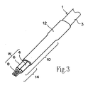
- a plastic heat-shrink tube 12 is caused to adhere tightly to the terminal part 10 and shielding covering 3 ( Figure 3).
- the front-end portion 14 of the terminal part 10 remains exposed.
- the plastic shrink tube 12 maintains equal distances between the drain wire 8 and the respective signal wires 4 and 6.
- the heat-shrink tube 12 prevents or alleviates mismatching of the differential impedance and maintains the balance among the electrical wires W, eliminating skewing, i.e., signal deviation, between the signal wires 4 and 6.
- skewing i.e., signal deviation
- the connection of the cable terminal part to an electrical component, i.e., a circuit board, will be described with reference to Figures 4 and 5.
- the exposed front-end portions 14 of the signal wires 4 and 6 are disposed on a first side, i.e., an upper side 20, of a board 16.
- the drain wire 8 is disposed on a second side, i.e., an underside 22, of the board 16.
- the signal wires 4 and 6 and drain wire 8 are flexible, the wires can be divided between the upper and lower surfaces of the board 16.
- the drain wire 8 and the exposed core wires 4a and 6a of the signal wires 4 and 6 are then respectively fastened by soldering to conductive pads 24, 18, 18.
- the conductive pad 24 is positioned at an intermediate point between the conductive pads 18, 18 on the opposite side of the board 16 ( Figure 5).
- Figure 6 is a front view of a male connector (plug connector) having a board 16 disposed with cables 1.
- a rectangular opening 34 is formed facing rearward in the housing 32 of the male connector 30.
- a pair of ribs 36, 36 are formed on the inside surfaces of the opening 34 so that the ribs protrude facing each other across the entire width of the opening 34 in a direction perpendicular to the direction of insertion of the male connector 30.
- a slot 38 formed between the ribs 36, 36 extends across the entire width of the opening 34.
- a board 16 having numerous contacts 40 is inserted and held in the slot 38.
- the contacts 40 are disposed on both surfaces of the board in a positional relationship.
- the tip end portions of the contacts 40 are exposed inside the opening 34 and constitute contact parts that make contact with the contacts of a second connector (not shown) that is engaged with the male connector 30.
Landscapes
- Engineering & Computer Science (AREA)
- Architecture (AREA)
- Civil Engineering (AREA)
- Structural Engineering (AREA)
- Insulated Conductors (AREA)
- Details Of Connecting Devices For Male And Female Coupling (AREA)
- Lining Or Joining Of Plastics Or The Like (AREA)
- Communication Cables (AREA)
- Processing Of Terminals (AREA)
- Cable Accessories (AREA)
Abstract
Description
Claims (6)
- An electrical cable (1) for termination to an electrical component, comprisingtwo differential transmission signal wires (4, 6) having respective core wires (4a, 6a) each with an outer insulating covering (4b, 6b);a drain wire (8) disposed adjacent to the differential transmission signal wires (4, 6) at a substantially equal distance from each of the differential transmission signal wires;a shielding covering (3) that surrounding the differential transmission signal wires (4, 6) and drain wire (8);an exposed area formed by stripping the shielding covering (3)from around the two differential transmission signal wires and the drain wire at a terminal part (10) of the electrical cable; anda heat-shrink tube (12) covering the exposed area and an end portion of the shielding covering (3), except for front end portions (14) of the differential transmission signal wires and drain wire, so that mutual distances between the differential transmission signal wires and the signal drain wire are maintained.
- The electrical cable of Claim 1 wherein the shielding covering (3) has an insulating outer layer (3a) comprising a polyester film.
- The electrical cable of Claim 2 wherein the insulating outer layer (3a) of the shielding covering (3) has an inside surface covered by aluminium foil (3b).
- The electrical cable of Claim 1, 2 or 3 wherein the outer insulating covering (4b, 6b) of the core wires (4a,6a) of the differential transmission signal wires (4 and 6) comprise a polyolefin-type resin.
- The electrical cable of Claim 4 wherein the drain wire (8) is located in a position that is separated from the core wires (4a, 6a) of the differential transmission signal wires (4, 6) by a distance corresponding roughly to the thickness of the outer insulating covering (4b and 6b) of the core wires.
- A method for terminating an electrical cable (1), comprisingstripping a shielding covering (3) over a given length from an end portion of two differential transmission signal wires (4, 6) and a drain wire (8) at a terminal part (10) of the electrical cable (1);covering an area around the two differential transmission signal wires (4, 6) and the drain wire (8) exposed by the stripping step with a heat-shrink tube (12), the heat-shrink tube (12) also covering an end of the shielding covering (3); andexposing the front end portions (14) of the differential transmission signal wires and the drain wire exposed by the stripping step, whereby the heat-shrink tube (12) cooperates with the differential transmission signal wires and the drain wire in the covered area to maintain mutual distances between the differential transmission signal wires and the drain wire.
Applications Claiming Priority (2)
| Application Number | Priority Date | Filing Date | Title |
|---|---|---|---|
| JP2000328598A JP3645170B2 (en) | 2000-10-27 | 2000-10-27 | Electric cable end structure and electric cable end processing method |
| JP2000328598 | 2000-10-27 |
Publications (1)
| Publication Number | Publication Date |
|---|---|
| EP1202419A1 true EP1202419A1 (en) | 2002-05-02 |
Family
ID=18805428
Family Applications (1)
| Application Number | Title | Priority Date | Filing Date |
|---|---|---|---|
| EP01309107A Withdrawn EP1202419A1 (en) | 2000-10-27 | 2001-10-26 | Electrical cable terminal part structure and method of termination |
Country Status (6)
| Country | Link |
|---|---|
| US (1) | US6752633B2 (en) |
| EP (1) | EP1202419A1 (en) |
| JP (1) | JP3645170B2 (en) |
| KR (1) | KR100776450B1 (en) |
| CN (1) | CN1222953C (en) |
| TW (1) | TW516044B (en) |
Cited By (7)
| Publication number | Priority date | Publication date | Assignee | Title |
|---|---|---|---|---|
| WO2012003347A1 (en) * | 2010-06-30 | 2012-01-05 | Apple Inc. | Method of manufacturing a connector insert, connector insert and cable |
| DE102011001225A1 (en) | 2011-03-11 | 2012-09-13 | Harting Electronics Gmbh & Co. Kg | Connection device and connection method for high-frequency digital signals |
| US8312302B2 (en) | 2010-06-30 | 2012-11-13 | Apple Inc. | Power distribution inside cable |
| US8463881B1 (en) | 2007-10-01 | 2013-06-11 | Apple Inc. | Bridging mechanism for peer-to-peer communication |
| US8966134B2 (en) | 2011-02-23 | 2015-02-24 | Apple Inc. | Cross-over and bypass configurations for high-speed data transmission |
| US9112310B2 (en) | 2010-06-30 | 2015-08-18 | Apple Inc. | Spark gap for high-speed cable connectors |
| CN105304175A (en) * | 2015-11-18 | 2016-02-03 | 安徽宏源特种电缆集团有限公司 | Brach shielding processing structure of wire harness network of vehicle-mounted chassis and processing method |
Families Citing this family (61)
| Publication number | Priority date | Publication date | Assignee | Title |
|---|---|---|---|---|
| US6939174B2 (en) * | 2003-07-01 | 2005-09-06 | Hon Hai Precision Ind. Co., Ltd. | Cable assembly with internal circuit modules |
| US20060001163A1 (en) * | 2004-06-30 | 2006-01-05 | Mohammad Kolbehdari | Groundless flex circuit cable interconnect |
| US7114990B2 (en) | 2005-01-25 | 2006-10-03 | Corning Gilbert Incorporated | Coaxial cable connector with grounding member |
| JP4738990B2 (en) * | 2005-11-17 | 2011-08-03 | タイコエレクトロニクスジャパン合同会社 | DIFFERENTIAL TRANSMISSION CONNECTOR, BOARD INSTALLATION DIFFERENTIAL TRANSMISSION CONNECTOR AND DIFFERENTIAL TRANSMISSION CONNECTOR ASSEMBLY MATCHING THEM |
| JP4933344B2 (en) * | 2007-05-16 | 2012-05-16 | 株式会社オートネットワーク技術研究所 | Shielded twisted pair cable |
| GB2459658A (en) * | 2008-04-29 | 2009-11-04 | Tyco Electronics Ltd Uk | Power Cable |
| TWI419178B (en) * | 2008-07-31 | 2013-12-11 | Sumitomo Electric Industries | Differential transmission signal cable and composite cable containing the same |
| US8025518B2 (en) | 2009-02-24 | 2011-09-27 | Corning Gilbert Inc. | Coaxial connector with dual-grip nut |
| CN101494040B (en) * | 2009-03-06 | 2013-05-08 | 友达光电股份有限公司 | Drive device for driving liquid crystal display panel |
| US8287320B2 (en) | 2009-05-22 | 2012-10-16 | John Mezzalingua Associates, Inc. | Coaxial cable connector having electrical continuity member |
| US9017101B2 (en) | 2011-03-30 | 2015-04-28 | Ppc Broadband, Inc. | Continuity maintaining biasing member |
| US9570845B2 (en) | 2009-05-22 | 2017-02-14 | Ppc Broadband, Inc. | Connector having a continuity member operable in a radial direction |
| CN101902007B (en) * | 2009-06-01 | 2012-05-23 | 北京七六一通信雷达有限公司 | Multi-strand excitation wire end processing method |
| JP5463849B2 (en) | 2009-10-22 | 2014-04-09 | 住友電気工業株式会社 | Multi-core coaxial cable and manufacturing method thereof |
| US8272893B2 (en) | 2009-11-16 | 2012-09-25 | Corning Gilbert Inc. | Integrally conductive and shielded coaxial cable connector |
| TWI549386B (en) | 2010-04-13 | 2016-09-11 | 康寧吉伯特公司 | Coaxial connector with inhibited ingress and improved grounding |
| US8888526B2 (en) | 2010-08-10 | 2014-11-18 | Corning Gilbert, Inc. | Coaxial cable connector with radio frequency interference and grounding shield |
| JP2012064338A (en) * | 2010-09-14 | 2012-03-29 | Fujitsu Ltd | Terminal structure of coaxial cable, connector and board unit |
| CN102456437A (en) * | 2010-10-26 | 2012-05-16 | 富士康(昆山)电脑接插件有限公司 | Cable, heat-shrinkable sleeve with shielding function, and cable manufacturing method |
| CN102456439A (en) * | 2010-10-26 | 2012-05-16 | 富士康(昆山)电脑接插件有限公司 | Cable, heat-shrinkable sleeve with shielding function and manufacturing method of cable |
| CN102456438A (en) * | 2010-10-26 | 2012-05-16 | 富士康(昆山)电脑接插件有限公司 | Cable and heat-shrinkable sleeve thereof |
| TWI558022B (en) | 2010-10-27 | 2016-11-11 | 康寧吉伯特公司 | Push-on cable connector with a coupler and retention and release mechanism |
| JP5589778B2 (en) * | 2010-11-05 | 2014-09-17 | 日立金属株式会社 | Connection structure and connection method for differential signal transmission cable and circuit board |
| US8337229B2 (en) | 2010-11-11 | 2012-12-25 | John Mezzalingua Associates, Inc. | Connector having a nut-body continuity element and method of use thereof |
| US8366481B2 (en) | 2011-03-30 | 2013-02-05 | John Mezzalingua Associates, Inc. | Continuity maintaining biasing member |
| US9711917B2 (en) | 2011-05-26 | 2017-07-18 | Ppc Broadband, Inc. | Band spring continuity member for coaxial cable connector |
| US9203167B2 (en) | 2011-05-26 | 2015-12-01 | Ppc Broadband, Inc. | Coaxial cable connector with conductive seal |
| JP5314734B2 (en) * | 2011-07-06 | 2013-10-16 | 富士フイルム株式会社 | Endoscope |
| US9190744B2 (en) | 2011-09-14 | 2015-11-17 | Corning Optical Communications Rf Llc | Coaxial cable connector with radio frequency interference and grounding shield |
| US20130072057A1 (en) | 2011-09-15 | 2013-03-21 | Donald Andrew Burris | Coaxial cable connector with integral radio frequency interference and grounding shield |
| JP5817674B2 (en) * | 2011-09-16 | 2015-11-18 | 日立金属株式会社 | Non-drain differential signal transmission cable and its ground connection structure |
| KR200462823Y1 (en) | 2011-11-04 | 2012-10-02 | 부전전자 주식회사 | Cord having integral stopper and mold for making the same |
| US9136654B2 (en) | 2012-01-05 | 2015-09-15 | Corning Gilbert, Inc. | Quick mount connector for a coaxial cable |
| US9407016B2 (en) | 2012-02-22 | 2016-08-02 | Corning Optical Communications Rf Llc | Coaxial cable connector with integral continuity contacting portion |
| US9287659B2 (en) | 2012-10-16 | 2016-03-15 | Corning Optical Communications Rf Llc | Coaxial cable connector with integral RFI protection |
| US9147963B2 (en) | 2012-11-29 | 2015-09-29 | Corning Gilbert Inc. | Hardline coaxial connector with a locking ferrule |
| US9153911B2 (en) | 2013-02-19 | 2015-10-06 | Corning Gilbert Inc. | Coaxial cable continuity connector |
| US9172154B2 (en) | 2013-03-15 | 2015-10-27 | Corning Gilbert Inc. | Coaxial cable connector with integral RFI protection |
| JP5690455B1 (en) * | 2013-04-16 | 2015-03-25 | オリンパスメディカルシステムズ株式会社 | Board connection structure |
| US10290958B2 (en) | 2013-04-29 | 2019-05-14 | Corning Optical Communications Rf Llc | Coaxial cable connector with integral RFI protection and biasing ring |
| CN105284015B (en) | 2013-05-20 | 2019-03-08 | 康宁光电通信Rf有限责任公司 | Coaxial Cable Connectors with Integral RFI Protection |
| US9548557B2 (en) | 2013-06-26 | 2017-01-17 | Corning Optical Communications LLC | Connector assemblies and methods of manufacture |
| US9048599B2 (en) | 2013-10-28 | 2015-06-02 | Corning Gilbert Inc. | Coaxial cable connector having a gripping member with a notch and disposed inside a shell |
| US11228145B2 (en) * | 2014-09-04 | 2022-01-18 | Autonetworks Technologies, Ltd. | Communication connector |
| JP6098609B2 (en) * | 2014-10-15 | 2017-03-22 | トヨタ自動車株式会社 | HYDROGEN SUPPLY PIPE AND METHOD FOR PRODUCING HYDROGEN SUPPLY PIPE |
| US9548572B2 (en) | 2014-11-03 | 2017-01-17 | Corning Optical Communications LLC | Coaxial cable connector having a coupler and a post with a contacting portion and a shoulder |
| JP6348829B2 (en) | 2014-12-09 | 2018-06-27 | ホシデン株式会社 | Cable assembly and method for manufacturing cable assembly |
| US9590287B2 (en) | 2015-02-20 | 2017-03-07 | Corning Optical Communications Rf Llc | Surge protected coaxial termination |
| US10033122B2 (en) | 2015-02-20 | 2018-07-24 | Corning Optical Communications Rf Llc | Cable or conduit connector with jacket retention feature |
| JP6459747B2 (en) * | 2015-04-21 | 2019-01-30 | 株式会社オートネットワーク技術研究所 | Communication connector |
| US10211547B2 (en) | 2015-09-03 | 2019-02-19 | Corning Optical Communications Rf Llc | Coaxial cable connector |
| US9525220B1 (en) | 2015-11-25 | 2016-12-20 | Corning Optical Communications LLC | Coaxial cable connector |
| JP6589752B2 (en) * | 2016-06-28 | 2019-10-16 | 日立金属株式会社 | Differential signal transmission cable and multi-core differential signal transmission cable |
| JP6756208B2 (en) * | 2016-09-16 | 2020-09-16 | 株式会社デンソー | Cables, electric power steering devices using them, and methods for manufacturing cables |
| KR102482155B1 (en) * | 2017-10-17 | 2022-12-29 | 에이치엘만도 주식회사 | Fuse pad, printed circuit board including the fuse pad and method for manufacturing thereof |
| ES2987411T3 (en) * | 2018-03-22 | 2024-11-14 | Molex Llc | System and procedure for sending data from individual sensors through a shared cable |
| US11837816B2 (en) * | 2018-05-31 | 2023-12-05 | Hydra-Electric Company | Method of sealing cable exit for moisture and vapor intrusion |
| TWI675510B (en) * | 2019-01-14 | 2019-10-21 | 燁元電子有限公司 | Connecting structure for a cable and printed circuit board |
| CN110071409B (en) * | 2019-03-12 | 2020-05-22 | 国网山东省电力公司临沂供电公司 | Cable joint preparation device and preparation method thereof |
| TWI689949B (en) * | 2019-08-28 | 2020-04-01 | 貿聯國際股份有限公司 | Circuit board assembly with high-speed wire |
| US12034264B2 (en) | 2021-03-31 | 2024-07-09 | Corning Optical Communications Rf Llc | Coaxial cable connector assemblies with outer conductor engagement features and methods for using the same |
Citations (3)
| Publication number | Priority date | Publication date | Assignee | Title |
|---|---|---|---|---|
| US3980382A (en) | 1974-06-03 | 1976-09-14 | Raychem Corporation | Matched impedance coaxial cable to printed circuit board terminator |
| GB1508997A (en) * | 1974-05-23 | 1978-04-26 | Raychem Sa Nv | Electrical connector |
| US5547395A (en) * | 1992-02-17 | 1996-08-20 | Raychem S.A. | Coaxial cable termination arrangement |
Family Cites Families (7)
| Publication number | Priority date | Publication date | Assignee | Title |
|---|---|---|---|---|
| DE2931710A1 (en) | 1979-08-04 | 1981-02-19 | Bayer Ag | ANTHRACHINONE-AZOMETHINE COMPOUNDS, METHOD FOR THE PRODUCTION THEREOF, METHOD FOR COLORING SYNTHETIC FIBER MATERIALS AND FOR PIGMENTING ORGANIC MACROMOLECULAR SUBSTANCES |
| US4682840A (en) * | 1983-09-26 | 1987-07-28 | Amp Incorporated | Electrical connection and method of making same |
| US5371322A (en) * | 1993-03-15 | 1994-12-06 | Selmeski; Eugene D. | Antenna wire coupling |
| US5478258A (en) * | 1993-12-20 | 1995-12-26 | Wang; Tsan-Chi | BNC connector and PC board arrangement |
| US5470253A (en) * | 1994-10-03 | 1995-11-28 | Caterpillar Inc. | Engine wiring system |
| JPH10223051A (en) | 1997-02-03 | 1998-08-21 | Harness Sogo Gijutsu Kenkyusho:Kk | Termination structure of combined shielded wires |
| US6380485B1 (en) * | 2000-08-08 | 2002-04-30 | International Business Machines Corporation | Enhanced wire termination for twinax wires |
-
2000
- 2000-10-27 JP JP2000328598A patent/JP3645170B2/en not_active Expired - Fee Related
-
2001
- 2001-10-19 KR KR1020010064619A patent/KR100776450B1/en not_active Expired - Fee Related
- 2001-10-24 US US10/004,052 patent/US6752633B2/en not_active Expired - Fee Related
- 2001-10-26 CN CNB011375272A patent/CN1222953C/en not_active Expired - Fee Related
- 2001-10-26 TW TW090126497A patent/TW516044B/en not_active IP Right Cessation
- 2001-10-26 EP EP01309107A patent/EP1202419A1/en not_active Withdrawn
Patent Citations (3)
| Publication number | Priority date | Publication date | Assignee | Title |
|---|---|---|---|---|
| GB1508997A (en) * | 1974-05-23 | 1978-04-26 | Raychem Sa Nv | Electrical connector |
| US3980382A (en) | 1974-06-03 | 1976-09-14 | Raychem Corporation | Matched impedance coaxial cable to printed circuit board terminator |
| US5547395A (en) * | 1992-02-17 | 1996-08-20 | Raychem S.A. | Coaxial cable termination arrangement |
Cited By (18)
| Publication number | Priority date | Publication date | Assignee | Title |
|---|---|---|---|---|
| US8463881B1 (en) | 2007-10-01 | 2013-06-11 | Apple Inc. | Bridging mechanism for peer-to-peer communication |
| US8976799B1 (en) | 2007-10-01 | 2015-03-10 | Apple Inc. | Converged computer I/O system and bridging mechanism for peer-to-peer communication |
| US8862912B2 (en) | 2010-06-30 | 2014-10-14 | Apple Inc. | Power distribution inside cable |
| US9274579B2 (en) | 2010-06-30 | 2016-03-01 | Apple Inc. | Circuitry for active cable |
| US8327536B2 (en) | 2010-06-30 | 2012-12-11 | Apple Inc. | Method of manufacturing high-speed connector inserts and cables |
| US9494989B2 (en) | 2010-06-30 | 2016-11-15 | Apple Inc. | Power distribution inside cable |
| US8516238B2 (en) | 2010-06-30 | 2013-08-20 | Apple Inc. | Circuitry for active cable |
| US8683190B2 (en) | 2010-06-30 | 2014-03-25 | Apple Inc. | Circuitry for active cable |
| WO2012003347A1 (en) * | 2010-06-30 | 2012-01-05 | Apple Inc. | Method of manufacturing a connector insert, connector insert and cable |
| US8312302B2 (en) | 2010-06-30 | 2012-11-13 | Apple Inc. | Power distribution inside cable |
| US9385478B2 (en) | 2010-06-30 | 2016-07-05 | Apple Inc. | High-speed connector inserts and cables |
| US9112310B2 (en) | 2010-06-30 | 2015-08-18 | Apple Inc. | Spark gap for high-speed cable connectors |
| US8966134B2 (en) | 2011-02-23 | 2015-02-24 | Apple Inc. | Cross-over and bypass configurations for high-speed data transmission |
| US10372650B2 (en) | 2011-02-23 | 2019-08-06 | Apple Inc. | Cross-over and bypass configurations for high-speed data transmission |
| US9161436B2 (en) | 2011-03-11 | 2015-10-13 | HARTING Electronics GmbH | Connection device and connection method for high-frequency digital signals |
| DE102011001225A1 (en) | 2011-03-11 | 2012-09-13 | Harting Electronics Gmbh & Co. Kg | Connection device and connection method for high-frequency digital signals |
| WO2012122974A1 (en) | 2011-03-11 | 2012-09-20 | Harting Electronics Gmbh & Co. Kg | Connection device and connection method for high-frequency digital signals |
| CN105304175A (en) * | 2015-11-18 | 2016-02-03 | 安徽宏源特种电缆集团有限公司 | Brach shielding processing structure of wire harness network of vehicle-mounted chassis and processing method |
Also Published As
| Publication number | Publication date |
|---|---|
| US20020050386A1 (en) | 2002-05-02 |
| JP3645170B2 (en) | 2005-05-11 |
| TW516044B (en) | 2003-01-01 |
| CN1351356A (en) | 2002-05-29 |
| JP2002135938A (en) | 2002-05-10 |
| KR100776450B1 (en) | 2007-11-16 |
| KR20020033052A (en) | 2002-05-04 |
| US6752633B2 (en) | 2004-06-22 |
| CN1222953C (en) | 2005-10-12 |
Similar Documents
| Publication | Publication Date | Title |
|---|---|---|
| US6752633B2 (en) | Electrical cable terminal part structure and treatment method | |
| CN100340034C (en) | Connectors with improved grounding | |
| JP4652454B2 (en) | Impedance-adjusted termination assembly and connector including the assembly | |
| KR100256927B1 (en) | Shield connection system of high speed cable | |
| CN107887714B (en) | Cable connection structure and cable connector | |
| US5478252A (en) | Disconnectable male connector for communications networks | |
| US20040266273A1 (en) | Cable assembly with internal circuit modules | |
| JPH0520212U (en) | coaxial cable | |
| TWI808370B (en) | Connector assembly including receptacle connector and plug connector | |
| CN110034443B (en) | an HDMI cable | |
| US20030060084A1 (en) | Connector | |
| KR100256928B1 (en) | System for terminating high speed cable shields | |
| US10424880B2 (en) | Shield connector and method for connecting same | |
| KR20100068002A (en) | Connector for coaxial cable | |
| EP0125760A1 (en) | Connector plug having shielding enclosure | |
| JP3267968B2 (en) | Shielded connectors for shielded cables | |
| JPS5842684B2 (en) | connector | |
| US20250087917A1 (en) | Connector set and connector | |
| US20080014789A1 (en) | Coaxial Cable Grounding Structure, Connector and Method for Connecting Cable In Said Connector | |
| EP0473049B1 (en) | A conductive shell for clamping onto a shielded electrical connector | |
| JP3016041B2 (en) | Connection device for shielded twisted cable | |
| JPS6244457Y2 (en) | ||
| EP1042168A2 (en) | Assembly for splicing multiple screened cables | |
| US20250062574A1 (en) | Electrical-connector-equipper cable | |
| EP4651309A1 (en) | Wire connection structure, wire connection structure manufacturing method, and wire assembly |
Legal Events
| Date | Code | Title | Description |
|---|---|---|---|
| PUAI | Public reference made under article 153(3) epc to a published international application that has entered the european phase |
Free format text: ORIGINAL CODE: 0009012 |
|
| AK | Designated contracting states |
Kind code of ref document: A1 Designated state(s): AT BE CH CY DE DK ES FI FR GB GR IE IT LI LU MC NL PT SE TR Kind code of ref document: A1 Designated state(s): DE FR GB NL |
|
| AX | Request for extension of the european patent |
Free format text: AL;LT;LV;MK;RO;SI |
|
| 17P | Request for examination filed |
Effective date: 20021021 |
|
| AKX | Designation fees paid |
Free format text: DE FR GB NL |
|
| 17Q | First examination report despatched |
Effective date: 20071113 |
|
| STAA | Information on the status of an ep patent application or granted ep patent |
Free format text: STATUS: THE APPLICATION IS DEEMED TO BE WITHDRAWN |
|
| 18D | Application deemed to be withdrawn |
Effective date: 20100503 |