EP1203636A1 - Procédé de réglage d'une machine pour l'usinage de pièces comprenant plusieurs emplacements à usiner simultanément, et machine pour la mise en oeuvre de ce procédé. - Google Patents
Procédé de réglage d'une machine pour l'usinage de pièces comprenant plusieurs emplacements à usiner simultanément, et machine pour la mise en oeuvre de ce procédé. Download PDFInfo
- Publication number
- EP1203636A1 EP1203636A1 EP01402700A EP01402700A EP1203636A1 EP 1203636 A1 EP1203636 A1 EP 1203636A1 EP 01402700 A EP01402700 A EP 01402700A EP 01402700 A EP01402700 A EP 01402700A EP 1203636 A1 EP1203636 A1 EP 1203636A1
- Authority
- EP
- European Patent Office
- Prior art keywords
- support
- machining
- relative
- units
- workpiece
- Prior art date
- Legal status (The legal status is an assumption and is not a legal conclusion. Google has not performed a legal analysis and makes no representation as to the accuracy of the status listed.)
- Withdrawn
Links
- 238000003754 machining Methods 0.000 title claims abstract description 91
- 238000000034 method Methods 0.000 title claims description 16
- 238000001514 detection method Methods 0.000 claims description 6
- 230000000694 effects Effects 0.000 claims description 3
- 238000004519 manufacturing process Methods 0.000 description 4
- 230000006978 adaptation Effects 0.000 description 2
- 238000012800 visualization Methods 0.000 description 2
- 230000000903 blocking effect Effects 0.000 description 1
- 230000001143 conditioned effect Effects 0.000 description 1
- 238000013479 data entry Methods 0.000 description 1
- 230000007547 defect Effects 0.000 description 1
- 238000010586 diagram Methods 0.000 description 1
- 238000006073 displacement reaction Methods 0.000 description 1
- 230000010355 oscillation Effects 0.000 description 1
- 230000000007 visual effect Effects 0.000 description 1
Images


Classifications
-
- B—PERFORMING OPERATIONS; TRANSPORTING
- B24—GRINDING; POLISHING
- B24B—MACHINES, DEVICES, OR PROCESSES FOR GRINDING OR POLISHING; DRESSING OR CONDITIONING OF ABRADING SURFACES; FEEDING OF GRINDING, POLISHING, OR LAPPING AGENTS
- B24B47/00—Drives or gearings; Equipment therefor
- B24B47/22—Equipment for exact control of the position of the grinding tool or work at the start of the grinding operation
-
- B—PERFORMING OPERATIONS; TRANSPORTING
- B24—GRINDING; POLISHING
- B24B—MACHINES, DEVICES, OR PROCESSES FOR GRINDING OR POLISHING; DRESSING OR CONDITIONING OF ABRADING SURFACES; FEEDING OF GRINDING, POLISHING, OR LAPPING AGENTS
- B24B19/00—Single-purpose machines or devices for particular grinding operations not covered by any other main group
- B24B19/08—Single-purpose machines or devices for particular grinding operations not covered by any other main group for grinding non-circular cross-sections, e.g. shafts of elliptical or polygonal cross-section
- B24B19/12—Single-purpose machines or devices for particular grinding operations not covered by any other main group for grinding non-circular cross-sections, e.g. shafts of elliptical or polygonal cross-section for grinding cams or camshafts
- B24B19/125—Single-purpose machines or devices for particular grinding operations not covered by any other main group for grinding non-circular cross-sections, e.g. shafts of elliptical or polygonal cross-section for grinding cams or camshafts electrically controlled, e.g. numerically controlled
-
- B—PERFORMING OPERATIONS; TRANSPORTING
- B24—GRINDING; POLISHING
- B24B—MACHINES, DEVICES, OR PROCESSES FOR GRINDING OR POLISHING; DRESSING OR CONDITIONING OF ABRADING SURFACES; FEEDING OF GRINDING, POLISHING, OR LAPPING AGENTS
- B24B27/00—Other grinding machines or devices
- B24B27/0076—Other grinding machines or devices grinding machines comprising two or more grinding tools
-
- B—PERFORMING OPERATIONS; TRANSPORTING
- B24—GRINDING; POLISHING
- B24B—MACHINES, DEVICES, OR PROCESSES FOR GRINDING OR POLISHING; DRESSING OR CONDITIONING OF ABRADING SURFACES; FEEDING OF GRINDING, POLISHING, OR LAPPING AGENTS
- B24B5/00—Machines or devices designed for grinding surfaces of revolution on work, including those which also grind adjacent plane surfaces; Accessories therefor
- B24B5/36—Single-purpose machines or devices
- B24B5/42—Single-purpose machines or devices for grinding crankshafts or crankpins
Definitions
- the present invention relates to an adjustment method a machine for machining parts having an axis and comprising several locations to be machined simultaneously, spaced along said axis, to adapt the machine to the machining of parts which differ in this which relates to the spacing of said locations to be machined, as well as to a machine for implementing this process.
- such machine has workpiece support and unit support machining on which several machining units exerting a clamping on the locations to be machined when they are in contact with these are mounted one behind the other following a direction parallel to the axis of the part while being movable in translation relative to each other and to their next support this direction.
- the machine also includes means for clamping to lock the machining units in position relative to their support.
- the workpiece support and the machining unit support are movable in translation relative to each other according to this same direction under the action of a translation system.
- the machine further comprises means for detecting the position of the support machining units in relation to the workpiece support and detection the position of each machining unit relative to the support of these units.
- the machine includes a control to which are connected the translation system, the position detection means, a data entry system and a visualization system.
- the setting consisting of adaptation to different rooms, for example to switch from the machining of a first part to the machining of a second part which differs from the first by spacing at least part of the locations to be machined on the workpiece, by manual translation of each of the machining units in relation to the support of these units, with visual control by the operator of the correct positioning of the machining units after translation and manual locking in position after control.
- This is an operation which, even with the assistance of a numerical control and a visualization system, is not only long, but also questionable since the result is directly conditioned by the operator's attention responsible for adjustment.
- all downtime a machine involved in the production chain for example of a machine for machining crankshafts, affects the whole chain. It is the same for any adjustment defect of a machine.
- the method according to the present invention is based on the surprising finding that on a machine with several units machining for machining parts having an axis and comprising several locations to be machined simultaneously, spaced along this axis, involving, for the adjustment of this machine on a specified part, directly the part in question and the order of the machine, it was possible to operate this setting not only more quickly, but still more reliably, by breaking free in a large measure of the hazards inherent in any manual intervention.
- the displacement of the first support relative to the other can be done using a translation system that can act either on the support of the workpiece, ie on the support of the machining units.
- the support of the part can comprise for example a tip and tailstock in the case of parts driven in rotation around an axis during machining such as crankshafts, the point and the tailstock can for example be mounted on a table mobile in translation under the action of a system, for example a pinion / digitally controlled rack.
- the support of the machining units can include, for example example, a succession of movable tool-carrying arms in translation on guide rails of said support, the tool arms preferably each carrying several tools such as for example abrasive stones or abrasive band application pads which, during machining, clamp the location to be machined together, by example a journal or crank pin in case of machining of crankshafts.
- the support of the machining units can be movable in translation on machine guide rails under the action of a system for example with screw / nut with numerical control.
- each machining unit of the machine can be equipped with clamping means actuated from the control of the machine for its blocking on the support of the machining units, which also avoids any manual intervention for clamping.
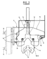
- the machine as illustrated in Figures 1 and 2 is a machine for superfinishing the spans (pins and crank pins) of crankshafts, whose general structure corresponds to that of machines of this type as marketed for years by the plaintiff.
- the machine illustrated essentially comprises a support 1 for a crankshaft 2 to be machined and a support 3 for several units machining 4.
- the support 1 comprises a point 5 and a tailstock 6 mounted on a bench 9, jacks 7 and 8 allowing adjustment in translation in order to take the crankshafts and adapt to the length of crankshafts.
- the support 3 is mounted movable in translation on bars guide 10, the translation of the support being effected by the action of a translation system 11 constituted here by a screw / nut system with electric motor.
- each of the units machining 4 of the support 3 comprises an arm 12 mounted with mobility vertical and angular (slide 13, axis 14) in an arm holder 15 itself mounted with horizontal mobility on guide rails 16 of the support 3.
- the arm 12 carries three tools 17 at its lower part angularly offset by 120 ° from each other for machining a bearing 18 of crankshaft 2 with tightening of this bearing, for example three tools for applying abrasive tape.
- Clamping means 19 which are shown here as being of the hydraulic type are provided to block and unblock the arm holder 15 relative to the guide rails 16 of the support 3.
- the machine according to Figures 3 and 4 differs from the machine according to Figures 1 and 2 by the fact that the support 3 of the machining units 4 is fixed and therefore does not include guide rails (10) and translation system (21), the tip 5 and the tailstock 6 of the support 1 for a crankshaft 2 being mounted with the possibility of adjustment by jacks 7 and 8 on a table 20 which is movable in translation under the action of a translation system 21 constituted here by a rack and pinion system with an electric motor.
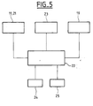
- control 22 preferably digital, to which are connected usually the translation system 11, 21, means 23 of position detection of the various moving parts of the machine, means 24 for entering the data relating to the parts to be machining and display means 25, as well as the means of clamping 19 which can thus be actuated, without intervention manual, directly from control 22.
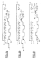
- Figures 6a to 6k which show in a simplified way the main elements of the machine according to Figure 3, namely a workpiece and its movable support in translation (crankshaft 2 to nine ranges 18.1 to 18.9, mounted between point 5 and tailstock 6), as well as a fixed support 3 with nine machining units (arms) 4.1 to 4.9 which are movable in translation relative to the support 3 and can be locked in position on the support, we have illustrated very schematically the different process steps for adjusting the this machine from a first part 2.1 to a second part 2.2.
- the nine arms 4.1 to 4.9 are locked on the support 3 with reciprocal spacing which corresponds to the reciprocal spacing of the ranges 18.1 to 18.9 of a first crankshaft 2.1, the arms being shown not tightened on the bearings.
- crankshaft 2.2 whose bearings 18.1 to 18.9 have greater spacing than on the first crankshaft 2.1 is fitted in place of crankshaft 2.1 between the point 5 and tailstock 6, the latter always occupying the same position (zero reference position).
- crankshaft 2.2 is displaced, using the translation system 21 of the support 1 (tip 5 and tailstock 6) and of control 22, in a position in which the position of the arm 4.9 coincides with the position of the seat 18.9 of the crankshaft.
- the arm 4.9 is tightened (in fact the tools 17 arm 4.9) in this position on the bearing 18.9.
- crankshaft 2.2 is displaced, using the translation system 21 of the support 1 (tip 5 and tailstock 6) and of control 22, by driving arm 4.9 still tight on the range 18.9, in a first reference position stored in control 22 relative to the zero reference position, and we locks the arm 4.9 in this position on the support 3.
- the arm 4.9 is released from the reach 18.9.
- phase 6c is repeated, but to bring the crankshaft 2.2 in a position in which the arm 4.8 coincides with the bearing 18.8 of the crankshaft 2.2.
- the arm 4.8 is released from the reach 18.8.
- the adjustment process is similar for a machine according to Figures 1 and 2, except that the support 3 is moved in translation machining units (arms) 4 instead of moving the support 1 in translation of part 2, comprising point 5 and tailstock 6.
- crankshaft bearing superfinishing machine does not limit anything the present invention to this application which constitutes only one illustrative example.
Landscapes
- Engineering & Computer Science (AREA)
- Mechanical Engineering (AREA)
- Grinding Of Cylindrical And Plane Surfaces (AREA)
Abstract
Description
répéter les opérations a) à d) successivement pour amener chacune des autres unités d'usinage à sa position de référence.
illustrent les différentes étapes du procédé de réglage d'une machine selon les figures 3 et 4.
Claims (10)
- Procédé de réglage d'une machine pour l'usinage de pièces ayant un axe et comprenant plusieurs emplacements à usiner simultanément, espacés suivant ledit axe, pour adapter la machine à l'usinage de pièces qui diffèrent en ce qui concerne l'espacement desdits emplacements à usiner, la machine comprenant un support de pièce et un support d'unités d'usinage sur lequel plusieurs unités d'usinage exerçant un effet de serrage sur les emplacements à usiner lorsqu'elles sont en contact avec de ces derniers, sont montées les unes derrière les autres suivant une direction parallèle à l'axe de la pièce en étant mobiles en translation suivant cette direction les unes par rapport aux autres et par rapport à leur support, des moyens de bridage pour bloquer les unités d'usinage en position les unes par rapport aux autres et par rapport à leur support, le support de pièce et le support des unités d'usinage étant mobiles en translation l'un par rapport à l'autre suivant cette même direction sous l'action d'un système de translation, des moyens de détection de la position du support des unités d'usinage par rapport au support de pièce et de détection de la position de chaque unité d'usinage par rapport au support de ces unités, et une commande à laquelle sont reliés le système de translation, les moyens de détection de position, des moyens d'introduction de données concernant la pièce à usiner et des moyens de visualisation, caractérisé par le fait qu'il consiste, à partir de positions quelconques, mémorisées dans la commande, des différentes unités d'usinage par rapport au support des unités d'usinage et du support des unités d'usinage par rapport au support de pièce, après montage d'une nouvelle pièce à usiner sur ledit support et après introduction dans la commande des données concernant cette nouvelle pièce, àa) - déplacer, à l'aide du système de translation et de la commande, un premier des deux supports par rapport à l'autre pour faire coïncider un premier emplacement à usiner de la pièce et une première unité d'usinage,b) - serrer la première unité d'usinage sur la pièce à l'endroit du premier emplacement à usiner et la bloquer sur le support des unités d'usinage,c) - déplacer, à l'aide du système de translation et de la commande, ledit premier support par rapport à l'autre pour amener la pièce et avec elle la première unité d'usinage à une position dans laquelle le premier emplacement à usiner de la pièce et la première unité d'usinage occupent une première position de référence mémorisée dans la commande,d) - desserrer la première unité d'usinage, et
répéter les opérations a) à d) successivement pour amener chacune des autres unités d'usinage à sa position de référence. - Procédé suivant la revendication 1, caractérisé par le fait qu'on déplace le premier support par rapport à l'autre à l'aide d'un système de translation agissant sur le support de la pièce à usiner.
- Procédé suivant la revendication 1, caractérisé par le fait qu'on déplace le premier support par rapport à l'autre à l'aide d'un système de translation agissant sur le support des unités d'usinage.
- Machine pour l'usinage de pièces ayant un axe et plusieurs emplacements à usiner simultanément, espacés suivant ledit axe, comprenant un support de pièce et un support d'unités d'usinage sur lequel plusieurs unités d'usinage comprenant chacune, pour un emplacement à usiner, plusieurs outils exerçant un effet de serrage sur l'emplacement à usiner lorsqu'ils sont en contact avec ce dernier, sont montées les unes derrière les autres suivant une direction parallèle à l'axe de la pièce en étant mobiles en translation suivant cette direction les unes par rapport aux autres et par rapport à leur support, des moyens de bridage pour bloquer les unités d'usinage en position les unes par rapport aux autres et par rapport à leur support, le support de pièce et le support des unités d'usinage étant mobiles en translation l'un par rapport à l'autre suivant cette même direction sous l'action d'un système de translation, des moyens de détection de la position du support des unités d'usinage par rapport au support de pièce et de détection de la position de chaque unité d'usinage par rapport au support de ces unités, et une commande à laquelle sont reliés le système de translation, les moyens de détection de position, des moyens d'introduction de données concernant la pièce à usiner et des moyens de visualisation, caractérisée par le fait que chaque unité d'usinage (4) de la machine est équipée de moyens de bridage (19) actionnés à partir de la commande (22) de la machine pour son blocage sur le support (3) des unités d'usinage.
- Machine suivant la revendication 4, caractérisée par le fait que les moyens de bridage (19) sont des moyens hydrauliques.
- Machine suivant la revendication 4 ou 5, caractérisée par le fait que le support (1) de la pièce comprend une pointe (5) et une contre-pointe (6) montées sur une table (20) mobile en translation sous l'action d'un système de translation (21).
- Machine suivant la revendication 4 ou 5, caractérisée par le fait que le support (3) des unités d'usinage (4) est mobile en translation sous l'action d'un système de translation (11).
- Machine suivant l'une quelconque des revendication 4 à 7, caractérisée par le fait que la commande (22) est une commande numérique.
- Machine suivant l'une quelconque des revendication 4 à 8, caractérisée par le fait que chaque unité d'usinage (4) comprend trois outils (17) décalés angulairement de 120° les uns des autre.
- Machine suivant l'une quelconque des revendication 4 à 9, caractérisée par le fait que les outils (17)sont des outils d'application de bande abrasive.
Applications Claiming Priority (2)
| Application Number | Priority Date | Filing Date | Title |
|---|---|---|---|
| FR0013642A FR2815563B1 (fr) | 2000-10-24 | 2000-10-24 | Procede de reglage d'une machine pour l'usinage de pieces comprenant plusieurs emplacements a usiner simultanement, et machine pour la mise en oeuvre de ce procede |
| FR0013642 | 2000-10-24 |
Publications (1)
| Publication Number | Publication Date |
|---|---|
| EP1203636A1 true EP1203636A1 (fr) | 2002-05-08 |
Family
ID=8855698
Family Applications (1)
| Application Number | Title | Priority Date | Filing Date |
|---|---|---|---|
| EP01402700A Withdrawn EP1203636A1 (fr) | 2000-10-24 | 2001-10-18 | Procédé de réglage d'une machine pour l'usinage de pièces comprenant plusieurs emplacements à usiner simultanément, et machine pour la mise en oeuvre de ce procédé. |
Country Status (2)
| Country | Link |
|---|---|
| EP (1) | EP1203636A1 (fr) |
| FR (1) | FR2815563B1 (fr) |
Citations (4)
| Publication number | Priority date | Publication date | Assignee | Title |
|---|---|---|---|---|
| US4505071A (en) * | 1982-11-13 | 1985-03-19 | Maschinenfabrik Ernst Thielenhaus Gmbh | Crankshaft-finishing machine |
| US4833834A (en) * | 1987-10-30 | 1989-05-30 | General Motors Corporation | Camshaft belt grinder |
| DE3926233C1 (en) * | 1989-08-09 | 1990-12-20 | Maschinenfabrik Ernst Thielenhaus Gmbh, 5600 Wuppertal, De | IC engine cam shaft grinder - has four equi-spaced valve cams per cylinder to form pattern for chucked shaft, and collet-type holder pairs for grinding tools |
| EP0844049A2 (fr) * | 1992-09-30 | 1998-05-27 | Western Atlas Inc. | Rectifieuse utilisant des rubans abrasifs, parallèles, multiples pour rectifier simultanement des surfaces sur une pièce |
Family Cites Families (1)
| Publication number | Priority date | Publication date | Assignee | Title |
|---|---|---|---|---|
| US6001003A (en) * | 1998-05-11 | 1999-12-14 | Park; Kyung | Wave beveling machine |
-
2000
- 2000-10-24 FR FR0013642A patent/FR2815563B1/fr not_active Expired - Fee Related
-
2001
- 2001-10-18 EP EP01402700A patent/EP1203636A1/fr not_active Withdrawn
Patent Citations (4)
| Publication number | Priority date | Publication date | Assignee | Title |
|---|---|---|---|---|
| US4505071A (en) * | 1982-11-13 | 1985-03-19 | Maschinenfabrik Ernst Thielenhaus Gmbh | Crankshaft-finishing machine |
| US4833834A (en) * | 1987-10-30 | 1989-05-30 | General Motors Corporation | Camshaft belt grinder |
| DE3926233C1 (en) * | 1989-08-09 | 1990-12-20 | Maschinenfabrik Ernst Thielenhaus Gmbh, 5600 Wuppertal, De | IC engine cam shaft grinder - has four equi-spaced valve cams per cylinder to form pattern for chucked shaft, and collet-type holder pairs for grinding tools |
| EP0844049A2 (fr) * | 1992-09-30 | 1998-05-27 | Western Atlas Inc. | Rectifieuse utilisant des rubans abrasifs, parallèles, multiples pour rectifier simultanement des surfaces sur une pièce |
Also Published As
| Publication number | Publication date |
|---|---|
| FR2815563B1 (fr) | 2003-02-21 |
| FR2815563A1 (fr) | 2002-04-26 |
Similar Documents
| Publication | Publication Date | Title |
|---|---|---|
| EP1606079B1 (fr) | Machine de meulage de verres optiques | |
| CH636543A5 (fr) | Machine-outil comprenant deux broches coaxiales opposees. | |
| FR2808464A1 (fr) | Machine a meuler et procede pour affuter des lames | |
| EP1568439B1 (fr) | Procédé et dispositif pour la réparation de dentures d'engrenages | |
| FR2545625A1 (fr) | Procede et appareil de commande de machine de coupe | |
| EP0090744B1 (fr) | Machine à scie annulaire pour le tronçonnage de tubes | |
| EP0055648A2 (fr) | Machine pour réaliser des pièces ayant des surfaces gauches de configuration déterminée | |
| BE898118A (fr) | Ensemble programmable de vissage de pièces sur des carrosseries de véhicules à moteur. | |
| EP1203636A1 (fr) | Procédé de réglage d'une machine pour l'usinage de pièces comprenant plusieurs emplacements à usiner simultanément, et machine pour la mise en oeuvre de ce procédé. | |
| EP3271109B1 (fr) | Procédé de réparation de la denture d'une couronne dentée | |
| FR2464773A1 (fr) | Dispositif pour le tournage de pieces flexibles | |
| FR2720964A1 (fr) | Dispositif de taillage de pièces sur un tour. | |
| FR2657281A1 (fr) | Machine pour tailler des engrenages. | |
| FR2832087A1 (fr) | Machine a encocher une piece tubulaire a usiner utilisable pour des operations generales de meulage | |
| FR2752760A1 (fr) | Unite d'usinage a tete rotative | |
| FR2687340A1 (fr) | Machine pour polissage de chants. | |
| FR2571291A1 (fr) | Machine de fraisage et polissage d'un chant d'une piece en materiau dur | |
| FR2479736A1 (fr) | Machine a travailler la pierre a commande par gabarit | |
| FR2521896A1 (fr) | Outil de calibrage a passe unique et machine a organe de compensation d'usure | |
| EP1641091B1 (fr) | Procède permettant d'usiner in situ la surface périphérique d'une pièce rotative, et dispositif permettant de mettre en oeuvre ledit procède | |
| EP0478439A1 (fr) | Machine adaptée à la fabrication de vis rectifiées à partir de barres à tailler | |
| CA3165276A1 (fr) | Electro-broche a avance integree avec changement automatique de porte-outil | |
| FR2825652A1 (fr) | Machine d'usinage par abrasif de portees d'une piece, notamment de superfinition de manetons de vilebrequins | |
| FR2575953A1 (fr) | Rectifieuse centerless pour la rectification exterieure de pieces cylindriques creuses, notamment de chemises pour cylindres de moteurs a combustion interne | |
| FR2538726A1 (fr) | Unite d'usinage polyvalente destinee a etre installee sur une piece a usiner pour y effectuer des usinages |
Legal Events
| Date | Code | Title | Description |
|---|---|---|---|
| PUAI | Public reference made under article 153(3) epc to a published international application that has entered the european phase |
Free format text: ORIGINAL CODE: 0009012 |
|
| AK | Designated contracting states |
Kind code of ref document: A1 Designated state(s): AT BE CH CY DE DK ES FI FR GB GR IE IT LI LU MC NL PT SE TR |
|
| AX | Request for extension of the european patent |
Free format text: AL;LT;LV;MK;RO;SI |
|
| 17P | Request for examination filed |
Effective date: 20021029 |
|
| AKX | Designation fees paid |
Designated state(s): DE ES GB IT |
|
| 17Q | First examination report despatched |
Effective date: 20041129 |
|
| GRAP | Despatch of communication of intention to grant a patent |
Free format text: ORIGINAL CODE: EPIDOSNIGR1 |
|
| RTI1 | Title (correction) |
Free format text: METHOD OF ADJUSTMENT OF A MACHINE FOR THE CONCURRENT MACHINING OF A WORKPIECE AT SEVERAL POSITIONS |
|
| STAA | Information on the status of an ep patent application or granted ep patent |
Free format text: STATUS: THE APPLICATION IS DEEMED TO BE WITHDRAWN |
|
| 18D | Application deemed to be withdrawn |
Effective date: 20060516 |