EP1203663A1 - Installation et procedé pour le traitement de solution de mouillage circulant - Google Patents
Installation et procedé pour le traitement de solution de mouillage circulant Download PDFInfo
- Publication number
- EP1203663A1 EP1203663A1 EP00123923A EP00123923A EP1203663A1 EP 1203663 A1 EP1203663 A1 EP 1203663A1 EP 00123923 A EP00123923 A EP 00123923A EP 00123923 A EP00123923 A EP 00123923A EP 1203663 A1 EP1203663 A1 EP 1203663A1
- Authority
- EP
- European Patent Office
- Prior art keywords
- fountain solution
- filtering device
- activated carbon
- circulation
- potential
- Prior art date
- Legal status (The legal status is an assumption and is not a legal conclusion. Google has not performed a legal analysis and makes no representation as to the accuracy of the status listed.)
- Granted
Links
Images


Classifications
-
- B—PERFORMING OPERATIONS; TRANSPORTING
- B41—PRINTING; LINING MACHINES; TYPEWRITERS; STAMPS
- B41F—PRINTING MACHINES OR PRESSES
- B41F7/00—Rotary lithographic machines
- B41F7/20—Details
- B41F7/24—Damping devices
- B41F7/32—Ducts, containers, or like supply devices for liquids
-
- B—PERFORMING OPERATIONS; TRANSPORTING
- B41—PRINTING; LINING MACHINES; TYPEWRITERS; STAMPS
- B41F—PRINTING MACHINES OR PRESSES
- B41F33/00—Indicating, counting, warning, control or safety devices
- B41F33/0054—Devices for controlling dampening
Definitions
- the present invention relates to a circulation treatment system and method for a fountain solution used in offset printing.
- a fountain solution circulation system constantly supplies a clear fountain solution containing each ingredient at a respective predetermined concentration to a vessel in a printing unit at a regular flow rate and temperature, collects the fountain solution which has passed through the vessel to restore the fountain solution to be clear, and supplies the fountain solution to the vessel again.
- Most of the recent offset rotary presses employ continuous circulation systems for fountain solutions.
- isopropyl alcohol (IPA) is used as an organic solvent.
- IPA improves wettability of a plate surface, thereby maintaining printing quality.
- the use of IPA may cause some safety and health problems for workers. Therefore, the amount of IPA used is limited to as small an amount as possible, or a fountain solution which does not include any IPA is used. In any case, control of a fountain solution is becoming more important.
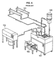
- FIG. 5 is a flow diagram showing a fountain solution circulation system 101 of a prior art.
- a raw fountain solution, water, an alcohol, etc. are mixed at precise proportions in a fountain solution mixer 102, and the mixed fresh fountain solution is supplied to the fountain solution circulation system 101.
- the fountain solution circulation system 101 removes contaminant in the fountain solution which has returned from a vessel 103 in a printing unit with a filtering device 104, and feeds solution back to a tank (not shown) inside the fountain solution circulation system 101.
- a fresh fountain solution is added from the fountain solution mixer 102 through a float valve.
- the fountain solution in the tank is kept at a predetermined temperature by a cooling device (not shown).
- An alcohol concentration controller 106 controls the concentration of alcohol, which easily evaporates.
- the fountain solution in the tank is continuously fed into the alcohol concentration controller 106.
- the concentration of a hydrogen ion is detected by constantly monitoring the pH of the fountain solution, and the fountain solution is supplemented with a required amount of alcohol to keep the predetermined alcohol concentration.
- IPA etching solution
- the concentration is controlled using a hydrometer.
- the concentration can be controlled by use of the fact that the conductivity of a fountain solution is proportioned to the concentrations of an etching solution and a concentrated alkali solution.
- organic substances generate in the fountain solution circulation system 101 and change the quality of the fountain solution.
- a fountain solution contains contaminant such as ink, paper particles and oil. Thus, it is important to keep the fountain solution circulation system 101 clean as a whole.
- a porous filter material such as a sponge filter is used in the filtering device 104, which removes the contaminant of the fountain solution returned from the vessel 103 through a porous layer of the filter only by mechanical filtering. Accordingly, the ability of removing impurities in the fountain solution depends on the dimension of the pores of the filter and, normally, impurities having a diameter less than 100 ⁇ m cannot be removed.
- a pressure posed on the fountain solution passing through a porous layer prevents the fountain solution from circulating at a predetermined flow rate. If the fountain solution does not circulate at a predetermined flow rate, the fountain solution loses normal functions, leading to deterioration of the printing quality. Furthermore, too small pores of the filter are easily clogged with impurities, which requires frequent maintenance of the filter.
- the prior art fountain solution circulation system 101 has further disadvantages due to the limitation of the filtering ability. Specifically, after circulating a fountain solution in the system for a few months, the fountain solution is contaminated and decomposed, and the quality of the fountain solution finally changes to the extent that it cannot be used as a fountain solution. Then, the fountain solution needs to be replaced. In many cases, a discarded fountain solution which has only been filtered by conventional mechanical filtering cannot meet legal standards for drainage of wastewater in terms of a biochemical oxygen demand (BOD), chemical oxygen demand (COD), n-hexane concentration and suspended solid (SS). Thus, the discarded fountain solution is regarded as an industrial waste, and wastewater of a fountain solution cannot be directly drained into rivers or the like. As a result, such waste disposal is committed to specialist companies at considerable cost.
- BOD biochemical oxygen demand
- COD chemical oxygen demand
- SS suspended solid
- a circulation treatment system and method for a fountain solution wherein the amounts of a BOD, COD, n-hexane concentration and SS in a fountain solution are reduced without posing any pressure on the fountain solution, thereby recycling the fountain solution without draining off.
- the circulation treatment system for a fountain solution of the present invention is a circulation treatment system for a fountain solution for circulating and purifying a fountain solution used in offset printing comprising a potential absorption filtering device using an absorbing effect of a zeta potential and an activated carbon filtering device using an absorbing effect of activated carbon, and the potential absorption filtering device and the activated carbon filtering device are provided in the course of a circulation passage for circulating the fountain solution.
- a potential absorption filter in a potential absorption filtering device is made to have a positive zeta potential.
- fine particle foreign matter which cannot be removed by a filter comprising a conventional porous filter material.
- fine particle foreign matter can be reduced without posing any pressure on a fountain solution passing through the potential absorption filter.
- a fountain solution can be decolorized and deodorized when passing through the activated carbon filter.
- the system of the present invention may comprise a potential absorption filtering device disposed on the upstream side of a circulation passage and an activated carbon filtering device disposed on the downstream side of the circulation passage.
- a potential absorption filtering device disposed on the upstream side of a circulation passage
- an activated carbon filtering device disposed on the downstream side of the circulation passage.
- the system of the present invention may further comprise a differential pressure gauge for detecting a differential pressure between a pressure at an introducing port of a circulation passage and a pressure at a discharging port of the circulation passage and an alarm device for giving an alarm in response to a result detected by the differential pressure gauge.
- a differential pressure between a pressure at an introducing port and a pressure at a discharging port is detected to give an alarm so that an operator is notified of the need for replacing a potential absorption filter and an activated carbon filter.
- a flow rate of a fountain solution is kept at a predetermined value, and an operator can easily control the fountain solution.
- a differential pressure between a pressure at an introducing port of a circulation passage and a pressure at a discharging port of the circulation passage is 2.2kg/cm 2 or less. Then, the flow rate of a fountain solution is optimum where a purifying effect by a potential absorption filtering device and an activated carbon filtering device can be most efficiently used, and the printing quality can be easily maintained. If a differential pressure is more than 2.2kg/cm 2 , a potential absorption filtering device or an activated carbon filtering device is clogged, which makes purification treatment insufficient.
- a circulation treatment method for a fountain solution using a circulation treatment system of the present invention is a circulation treatment method for a fountain solution for circulating and purifying a fountain solution used in offset printing comprising the steps of filtering a fountain solution using an absorbing effect of a zeta potential and filtering the fountain solution using an absorbing effect of an activated carbon.
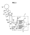
- FIG. 1 is a schematic view of a circulation treatment system for a fountain solution according to the present invention, wherein FIG. 1A is a plan view and FIG. 1B is a front view, and FIG. 2 is a flow diagram of the circulation treatment system for a fountain solution shown in FIG. 1.
- a circulation treatment system for a fountain solution 1 in the embodiment of the present invention comprises circulation passages 9a to 9d for circulating a fountain solution used in an offset rotary press by introducing the fountain solution from an introducing port 8a (on the upstream side) and discharging the fountain solution from a discharging port 8b (on the downstream side), a line pump 4 as a pumping device for forcibly circulating the fountain solution, a potential absorption filtering device 2 using an absorbing effect of a zeta potential, and an activated carbon filtering device 3 using an absorbing effect of activated carbon; the line pump 4, the potential absorption filtering device 2 and the activated carbon filtering device 3 being disposed in the course of the circulation passages 9a to 9d in this order.
- the circulation treatment system for a fountain solution 1 further comprises a differential pressure detecting transmitter 5 as a differential pressure gauge for detecting a differential pressure between a pressure in the circulation passage 9b which is outside the potential absorption filtering device 2 or on the side of the introducing port 8a and a pressure in the circulation passage 9d which is outside the activated carbon filtering device 3 or on the side of the discharging port 8b to transmit a detecting signal, a revolving light 6 as an alarm device for giving an alarm in response to a detected level of the detecting signal, and a control panel 7 for controlling the line pump 4, the differential pressure detecting transmitter 5 and the revolving light 6.
- a differential pressure detecting transmitter 5 as a differential pressure gauge for detecting a differential pressure between a pressure in the circulation passage 9b which is outside the potential absorption filtering device 2 or on the side of the introducing port 8a and a pressure in the circulation passage 9d which is outside the activated carbon filtering device 3 or on the side of the discharging port 8b to transmit a
- FIG. 3 is a partly cut out detailed view of a potential absorption cartridge enclosed in a housing of the potential absorption filtering device shown in FIG. 1.
- the potential absorption filtering device 2 encloses a potential absorption cartridge 20 as a replaceable potential absorption filter within a housing.
- the potential absorption cartridge 20 is composed of a plurality of cells each of which comprises a medium 21 mainly made of resin and cellulose, a polypropylene separator 22 and an edge seal 23. The cells are layered so as to sandwich a polypropylene ring seal 24 and assembled with a polypropylene core 25.
- a potential difference is generated on an interface between different phases.
- a potential caused by an electric double layer which is generated on an interface of a particle has a portion which does not play a dynamic role (fixed bed) and a portion which plays a dynamic role (diffusion layer).
- the electric phenomenon which occurs between different phases only when there is a relative motion is called an electrokinetic phenomenon, and the potential existing therein is called a zeta potential.
- fine particles and microorganisms in a fluid have a negative potential.
- fine particles of ink, paper, oil or the like contained in a fountain solution have a negative potential.
- the medium 21 in the potential absorption filtering device 2 characteristically has a positive zeta potential, and therefore can absorb and remove these fine particles which cannot be removed with a conventional 0.2 ⁇ m-membrane filter.
- fine particle foreign matter can be removed without posing any pressure on a fountain solution passing through the potential absorption filtering device 2.
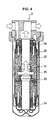
- FIG. 4 is a longitudinal sectional detailed view of an activated carbon filtering device shown in FIG. 1.
- An arrow in FIG. 4 indicates a flow of a fountain solution.
- the activated carbon filtering device 3 encloses an activated carbon cartridge 31 as a replaceable activated carbon filter in a housing 30.
- the activated carbon cartridge 31 comprises activated carbon of coconut husk 33, pre filter 34 and post filter 35 contained and heat-sealed in a polypropylene nonwoven fabric 32.
- the activated carbon of coconut husk 33 is hard grainy activated carbon of high quality and capable of effectively absorbing organic substances, color, odor and impurities from a fountain solution.
- the pre filter 34 and post filter 35 are made of cellulose fibers and melamine resin.
- the pre filter 34 absorbs precipitates such as dirt, rust and others, and the post filter 35 prevents the activated carbon of coconut husk 33 from flowing out.
- the fountain solution is filtered by the pre filter 34, and organic substances or the like in the fountain solution are absorbed by the activated carbon of coconut husk 33.
- a dampening section 11 of an offset rotary press is provided on a plate 16 and comprises a vessel 12 and a plurality of rollers 13, 14 and 15 arranged toward the plate 16 in this order.
- the circulation treatment system for a fountain solution 1 is connected to the vessel 12 in the dampening section 11 of the offset rotary press through connection passages 10a and 10b.
- the connection passages 10a and 10b are connected to the circulation treatment system for a fountain solution 1 via the introducing port 8a and the discharging port 8b, respectively.
- the fountain solution in the vessel 12 circulates through the connection passage 10a, the circulation passages 9a to 9d and the connection passage 10b in succession.
- the fountain solution in the vessel 12 is forcibly fed into the circulation passage 9a by the line pump 4.
- the fountain solution in the vessel 12 which is introduced into the circulation passage 9a from the connection passage 10a via the introducing port 8a is led into the potential absorption filtering device 2 passing through the circulation passage 9b.
- the potential absorption filtering device 2 fine particles of ink, paper and oil or the like contained in the fountain solution are absorbed and removed by an absorbing effect of a zeta potential.
- the fine particle foreign matter can be removed without posing any pressure on the fountain solution passing through the potential absorption filtering device 2.
- the fountain solution led to the activated carbon filtering device 3 via the circulation passage 9c is decolorized and deodorized, and is returned into the vessel 12 through the circulation passage 9d and the connection passage 10b.
- the amounts of a BOD, COD, n-hexane concentration and SS are reduced while keeping a predetermined flow rate by the potential absorption filtering device 2 and the activated carbon filtering device 3 provided in the course of the circulation passages 9a to 9d.
- the decolorized and deodorized fountain solution can be used over a long period and recycled without draining off.
- no wastewater of the fountain solution is generated, and thus it is not necessary to commit the disposal of wastewater to other companies, thereby reducing the running costs of a fountain solution used in offset printing.
- use of the thus purified fountain solution in offset printing improves printing quality.
- the circulation treatment system for a fountain solution 1 of the above-described embodiment has such a structure that the potential absorption filtering device 2 is disposed on the upstream side of the circulation passages 9a to 9b and the activated carbon filtering device 3 on the downstream side, fine particles of ink, paper, oil or the like contained in a fountain solution are first removed by the potential absorption filtering device 2 and then the fountain solution passes through the activated carbon filtering device 3. Accordingly, life of the activated carbon cartridge is significantly extended.
- the differential pressure detecting transmitter 5 provided in the circulation treatment system for a fountain solution 1 of the present invention detects a differential pressure between pressures at the circulation passages 9b and 9d, and turns on the revolving light 6 to give an alarm when the differential pressure is over 2.2kg/cm 2 .
- the differential pressure detecting transmitter 5 detects a sharp rise in the differential pressure in the medium 21 in the potential absorption filtering device 2 which occurs when the absorbing ability reaches the limit, and notifies an operator of timing for replacement of the potential absorption filtering device 2, thereby keeping a flow rate of a fountain solution at a predetermined value.
- the limit of the absorbing ability is detected from a rise in a differential pressure as well.
Landscapes
- Engineering & Computer Science (AREA)
- Mechanical Engineering (AREA)
- Water Treatment By Sorption (AREA)
Priority Applications (4)
| Application Number | Priority Date | Filing Date | Title |
|---|---|---|---|
| DE60030865T DE60030865T2 (de) | 2000-11-03 | 2000-11-03 | Anlage und Verfahren zur Behandelung von zirkulierendem Feuchtwasser |
| EP00123923A EP1203663B1 (fr) | 2000-11-03 | 2000-11-03 | Installation et procedé pour le traitement de solution de mouillage circulant |
| DE20023884U DE20023884U1 (de) | 2000-11-03 | 2000-11-03 | Kreislaufaufbereitungsanlage für Feuchtwasser |
| HK02107691.5A HK1046117B (en) | 2000-11-03 | 2002-10-23 | System and method for treating circulating fountain solution |
Applications Claiming Priority (1)
| Application Number | Priority Date | Filing Date | Title |
|---|---|---|---|
| EP00123923A EP1203663B1 (fr) | 2000-11-03 | 2000-11-03 | Installation et procedé pour le traitement de solution de mouillage circulant |
Publications (2)
| Publication Number | Publication Date |
|---|---|
| EP1203663A1 true EP1203663A1 (fr) | 2002-05-08 |
| EP1203663B1 EP1203663B1 (fr) | 2006-09-20 |
Family
ID=8170278
Family Applications (1)
| Application Number | Title | Priority Date | Filing Date |
|---|---|---|---|
| EP00123923A Expired - Lifetime EP1203663B1 (fr) | 2000-11-03 | 2000-11-03 | Installation et procedé pour le traitement de solution de mouillage circulant |
Country Status (3)
| Country | Link |
|---|---|
| EP (1) | EP1203663B1 (fr) |
| DE (2) | DE20023884U1 (fr) |
| HK (1) | HK1046117B (fr) |
Cited By (6)
| Publication number | Priority date | Publication date | Assignee | Title |
|---|---|---|---|---|
| EP1440795A1 (fr) * | 2003-01-22 | 2004-07-28 | Konica Minolta Holdings, Inc. | Procédé d'impression utilisant un précurseur de plaque d'impression planographique |
| EP1743769A3 (fr) * | 2005-06-24 | 2009-07-01 | Technotrans AG | Machine d'impression avec un appareil périphérique |
| JP2017081005A (ja) * | 2015-10-28 | 2017-05-18 | 東京インキ株式会社 | スプレー湿し水供給装置および湿し水供給方法 |
| CN108635954A (zh) * | 2018-06-25 | 2018-10-12 | 安徽唯宝印刷科技有限公司 | 一种润版液补偿循环系统 |
| JP2020093521A (ja) * | 2019-08-07 | 2020-06-18 | Bs—1グローバルシステムズ株式会社 | 濾過器、湿し水の循環システム、湿し水の循環方法、メラミン樹脂発泡体の使用方法 |
| JP2020093502A (ja) * | 2018-12-14 | 2020-06-18 | Bs—1グローバルシステムズ株式会社 | 濾過器、湿し水の循環システム、及び湿し水の循環方法 |
Citations (2)
| Publication number | Priority date | Publication date | Assignee | Title |
|---|---|---|---|---|
| US4292176A (en) * | 1976-12-08 | 1981-09-29 | Standard Oil Company (Indiana) | Use of activated carbon in waste water treating process |
| EP0170160A2 (fr) * | 1984-08-01 | 1986-02-05 | WEB ITALIA S.r.l. | Installation d'alimentation en solution de mouillage pour l'impression offset |
-
2000
- 2000-11-03 DE DE20023884U patent/DE20023884U1/de not_active Expired - Lifetime
- 2000-11-03 DE DE60030865T patent/DE60030865T2/de not_active Expired - Lifetime
- 2000-11-03 EP EP00123923A patent/EP1203663B1/fr not_active Expired - Lifetime
-
2002
- 2002-10-23 HK HK02107691.5A patent/HK1046117B/en not_active IP Right Cessation
Patent Citations (2)
| Publication number | Priority date | Publication date | Assignee | Title |
|---|---|---|---|---|
| US4292176A (en) * | 1976-12-08 | 1981-09-29 | Standard Oil Company (Indiana) | Use of activated carbon in waste water treating process |
| EP0170160A2 (fr) * | 1984-08-01 | 1986-02-05 | WEB ITALIA S.r.l. | Installation d'alimentation en solution de mouillage pour l'impression offset |
Cited By (8)
| Publication number | Priority date | Publication date | Assignee | Title |
|---|---|---|---|---|
| EP1440795A1 (fr) * | 2003-01-22 | 2004-07-28 | Konica Minolta Holdings, Inc. | Procédé d'impression utilisant un précurseur de plaque d'impression planographique |
| US7024997B2 (en) | 2003-01-22 | 2006-04-11 | Konica Minolta Holdings, Inc. | Printing method employing planographic printing plate material |
| EP1743769A3 (fr) * | 2005-06-24 | 2009-07-01 | Technotrans AG | Machine d'impression avec un appareil périphérique |
| JP2017081005A (ja) * | 2015-10-28 | 2017-05-18 | 東京インキ株式会社 | スプレー湿し水供給装置および湿し水供給方法 |
| CN108635954A (zh) * | 2018-06-25 | 2018-10-12 | 安徽唯宝印刷科技有限公司 | 一种润版液补偿循环系统 |
| CN108635954B (zh) * | 2018-06-25 | 2024-02-27 | 北京信诚世纪科技有限公司 | 一种润版液补偿循环系统 |
| JP2020093502A (ja) * | 2018-12-14 | 2020-06-18 | Bs—1グローバルシステムズ株式会社 | 濾過器、湿し水の循環システム、及び湿し水の循環方法 |
| JP2020093521A (ja) * | 2019-08-07 | 2020-06-18 | Bs—1グローバルシステムズ株式会社 | 濾過器、湿し水の循環システム、湿し水の循環方法、メラミン樹脂発泡体の使用方法 |
Also Published As
| Publication number | Publication date |
|---|---|
| DE20023884U1 (de) | 2007-03-01 |
| HK1046117A1 (en) | 2002-12-27 |
| DE60030865D1 (de) | 2006-11-02 |
| EP1203663B1 (fr) | 2006-09-20 |
| DE60030865T2 (de) | 2007-09-06 |
| HK1046117B (en) | 2006-12-08 |
Similar Documents
| Publication | Publication Date | Title |
|---|---|---|
| KR20080074222A (ko) | 역세정 체적 감소 프로세스 | |
| CN109437475A (zh) | 高盐废水处理方法及高盐废水处理系统 | |
| US6293198B1 (en) | Circulation treatment system and method for treating fountain solution | |
| TW496752B (en) | Damping water circulating treatment apparatus and method | |
| EP1203663B1 (fr) | Installation et procedé pour le traitement de solution de mouillage circulant | |
| EP0803274B1 (fr) | Procédé et appareil pour le traitement de l'eau provenant du lavage à contre-courant d'un filtre | |
| KR100617479B1 (ko) | 전기응집 활성탄 여과장치 | |
| CA2325942A1 (fr) | Systeme et methode de traitement par circulation de la solution de mouillage | |
| CN205838795U (zh) | 印染废水中水回用装置 | |
| JP3216495B2 (ja) | 水浄化方法および装置 | |
| CN118684295B (zh) | 一种低成本的微污染供水处理装置和方法 | |
| JP2020093502A (ja) | 濾過器、湿し水の循環システム、及び湿し水の循環方法 | |
| JP2002361049A (ja) | 洗車排水処理装置 | |
| CN217025555U (zh) | 一种玻璃清洗水循环利用系统 | |
| JP2002059531A (ja) | 湿し水浄化装置 | |
| JP2001260310A (ja) | 湿し水濾過装置 | |
| CN110862167A (zh) | 电极箔腐蚀废水处理系统及其处理工艺 | |
| KR20040024777A (ko) | 폐수절감형 정수시스템 | |
| CN1107075A (zh) | 印钞擦版废液处理并回用的方法 | |
| JPH11138163A (ja) | 水中油乳濁液処理方法及び水中油乳濁液処理装置 | |
| JP2003211625A (ja) | 湿し水循環処理装置および湿し水循環処理方法 | |
| CN223547783U (zh) | 一种基于膜分离技术的废水深度处理设备 | |
| JPH0847698A (ja) | 水浄化方法および装置 | |
| KR102854102B1 (ko) | 수질오염물질 처리용 체류형 분말활성탄 반응 장치 및 이를 포함하는 수질오염물질 처리 설비 | |
| CN218879498U (zh) | 一种低能耗降低废水中cod浓度的装置 |
Legal Events
| Date | Code | Title | Description |
|---|---|---|---|
| PUAI | Public reference made under article 153(3) epc to a published international application that has entered the european phase |
Free format text: ORIGINAL CODE: 0009012 |
|
| AK | Designated contracting states |
Kind code of ref document: A1 Designated state(s): AT BE CH CY DE DK ES FI FR GB GR IE IT LI LU MC NL PT SE TR |
|
| AX | Request for extension of the european patent |
Free format text: AL;LT;LV;MK;RO;SI |
|
| 17P | Request for examination filed |
Effective date: 20021004 |
|
| AKX | Designation fees paid |
Designated state(s): DE FR GB IT |
|
| GRAP | Despatch of communication of intention to grant a patent |
Free format text: ORIGINAL CODE: EPIDOSNIGR1 |
|
| GRAS | Grant fee paid |
Free format text: ORIGINAL CODE: EPIDOSNIGR3 |
|
| GRAA | (expected) grant |
Free format text: ORIGINAL CODE: 0009210 |
|
| AK | Designated contracting states |
Kind code of ref document: B1 Designated state(s): DE FR GB IT |
|
| PG25 | Lapsed in a contracting state [announced via postgrant information from national office to epo] |
Ref country code: IT Free format text: LAPSE BECAUSE OF FAILURE TO SUBMIT A TRANSLATION OF THE DESCRIPTION OR TO PAY THE FEE WITHIN THE PRESCRIBED TIME-LIMIT;WARNING: LAPSES OF ITALIAN PATENTS WITH EFFECTIVE DATE BEFORE 2007 MAY HAVE OCCURRED AT ANY TIME BEFORE 2007. THE CORRECT EFFECTIVE DATE MAY BE DIFFERENT FROM THE ONE RECORDED. Effective date: 20060920 |
|
| REG | Reference to a national code |
Ref country code: GB Ref legal event code: FG4D |
|
| REF | Corresponds to: |
Ref document number: 60030865 Country of ref document: DE Date of ref document: 20061102 Kind code of ref document: P |
|
| REG | Reference to a national code |
Ref country code: HK Ref legal event code: GR Ref document number: 1046117 Country of ref document: HK |
|
| ET | Fr: translation filed | ||
| PLBE | No opposition filed within time limit |
Free format text: ORIGINAL CODE: 0009261 |
|
| STAA | Information on the status of an ep patent application or granted ep patent |
Free format text: STATUS: NO OPPOSITION FILED WITHIN TIME LIMIT |
|
| 26N | No opposition filed |
Effective date: 20070621 |
|
| PGFP | Annual fee paid to national office [announced via postgrant information from national office to epo] |
Ref country code: IT Payment date: 20101126 Year of fee payment: 11 |
|
| PGFP | Annual fee paid to national office [announced via postgrant information from national office to epo] |
Ref country code: FR Payment date: 20111213 Year of fee payment: 12 |
|
| REG | Reference to a national code |
Ref country code: FR Ref legal event code: ST Effective date: 20130731 |
|
| PG25 | Lapsed in a contracting state [announced via postgrant information from national office to epo] |
Ref country code: IT Free format text: LAPSE BECAUSE OF NON-PAYMENT OF DUE FEES Effective date: 20121103 |
|
| PG25 | Lapsed in a contracting state [announced via postgrant information from national office to epo] |
Ref country code: FR Free format text: LAPSE BECAUSE OF NON-PAYMENT OF DUE FEES Effective date: 20121130 |
|
| PGFP | Annual fee paid to national office [announced via postgrant information from national office to epo] |
Ref country code: GB Payment date: 20131122 Year of fee payment: 14 |
|
| PGFP | Annual fee paid to national office [announced via postgrant information from national office to epo] |
Ref country code: DE Payment date: 20140130 Year of fee payment: 14 |
|
| REG | Reference to a national code |
Ref country code: DE Ref legal event code: R119 Ref document number: 60030865 Country of ref document: DE |
|
| GBPC | Gb: european patent ceased through non-payment of renewal fee |
Effective date: 20141103 |
|
| PG25 | Lapsed in a contracting state [announced via postgrant information from national office to epo] |
Ref country code: DE Free format text: LAPSE BECAUSE OF NON-PAYMENT OF DUE FEES Effective date: 20150602 Ref country code: GB Free format text: LAPSE BECAUSE OF NON-PAYMENT OF DUE FEES Effective date: 20141103 |