EP1205460A1 - Process for distillation, in a column with a dividing wall, of saturated hydrocarbons obtained by isomerisation - Google Patents
Process for distillation, in a column with a dividing wall, of saturated hydrocarbons obtained by isomerisation Download PDFInfo
- Publication number
- EP1205460A1 EP1205460A1 EP01309484A EP01309484A EP1205460A1 EP 1205460 A1 EP1205460 A1 EP 1205460A1 EP 01309484 A EP01309484 A EP 01309484A EP 01309484 A EP01309484 A EP 01309484A EP 1205460 A1 EP1205460 A1 EP 1205460A1
- Authority
- EP
- European Patent Office
- Prior art keywords
- fractionation
- zone
- stream
- column
- normal
- Prior art date
- Legal status (The legal status is an assumption and is not a legal conclusion. Google has not performed a legal analysis and makes no representation as to the accuracy of the status listed.)
- Granted
Links
- 238000006317 isomerization reaction Methods 0.000 title claims abstract description 88
- 238000000034 method Methods 0.000 title claims description 67
- 238000004821 distillation Methods 0.000 title description 12
- 229930195734 saturated hydrocarbon Natural products 0.000 title 1
- 238000000926 separation method Methods 0.000 claims abstract description 61
- 230000000274 adsorptive effect Effects 0.000 claims abstract description 53
- 238000005194 fractionation Methods 0.000 claims description 156
- 239000003463 adsorbent Substances 0.000 claims description 66
- AFABGHUZZDYHJO-UHFFFAOYSA-N 2-Methylpentane Chemical compound CCCC(C)C AFABGHUZZDYHJO-UHFFFAOYSA-N 0.000 claims description 48
- 239000000203 mixture Substances 0.000 claims description 42
- PFEOZHBOMNWTJB-UHFFFAOYSA-N 3-methylpentane Chemical compound CCC(C)CC PFEOZHBOMNWTJB-UHFFFAOYSA-N 0.000 claims description 41
- 229930195733 hydrocarbon Natural products 0.000 claims description 40
- 150000002430 hydrocarbons Chemical class 0.000 claims description 40
- 239000003054 catalyst Substances 0.000 claims description 37
- OFBQJSOFQDEBGM-UHFFFAOYSA-N Pentane Chemical compound CCCCC OFBQJSOFQDEBGM-UHFFFAOYSA-N 0.000 claims description 33
- 238000001179 sorption measurement Methods 0.000 claims description 32
- VLKZOEOYAKHREP-UHFFFAOYSA-N n-Hexane Chemical compound CCCCCC VLKZOEOYAKHREP-UHFFFAOYSA-N 0.000 claims description 30
- QWTDNUCVQCZILF-UHFFFAOYSA-N isopentane Chemical compound CCC(C)C QWTDNUCVQCZILF-UHFFFAOYSA-N 0.000 claims description 28
- GDOPTJXRTPNYNR-UHFFFAOYSA-N methylcyclopentane Chemical compound CC1CCCC1 GDOPTJXRTPNYNR-UHFFFAOYSA-N 0.000 claims description 28
- HNRMPXKDFBEGFZ-UHFFFAOYSA-N 2,2-dimethylbutane Chemical compound CCC(C)(C)C HNRMPXKDFBEGFZ-UHFFFAOYSA-N 0.000 claims description 18
- 150000001335 aliphatic alkanes Chemical class 0.000 claims description 17
- XDTMQSROBMDMFD-UHFFFAOYSA-N Cyclohexane Chemical compound C1CCCCC1 XDTMQSROBMDMFD-UHFFFAOYSA-N 0.000 claims description 13
- 238000004891 communication Methods 0.000 claims description 12
- WGECXQBGLLYSFP-UHFFFAOYSA-N 2,3-dimethylpentane Chemical compound CCC(C)C(C)C WGECXQBGLLYSFP-UHFFFAOYSA-N 0.000 claims description 10
- 230000000717 retained effect Effects 0.000 claims description 7
- 238000003795 desorption Methods 0.000 claims description 6
- BZHMBWZPUJHVEE-UHFFFAOYSA-N 2,3-dimethylpentane Natural products CC(C)CC(C)C BZHMBWZPUJHVEE-UHFFFAOYSA-N 0.000 claims description 5
- 238000004064 recycling Methods 0.000 claims description 4
- TVMXDCGIABBOFY-UHFFFAOYSA-N octane Chemical compound CCCCCCCC TVMXDCGIABBOFY-UHFFFAOYSA-N 0.000 abstract description 8
- 238000010276 construction Methods 0.000 abstract 1
- 239000000047 product Substances 0.000 description 47
- 150000001875 compounds Chemical class 0.000 description 32
- 239000007788 liquid Substances 0.000 description 27
- UFHFLCQGNIYNRP-UHFFFAOYSA-N Hydrogen Chemical compound [H][H] UFHFLCQGNIYNRP-UHFFFAOYSA-N 0.000 description 23
- 239000001257 hydrogen Substances 0.000 description 23
- 229910052739 hydrogen Inorganic materials 0.000 description 23
- 238000006243 chemical reaction Methods 0.000 description 20
- BASFCYQUMIYNBI-UHFFFAOYSA-N platinum Chemical compound [Pt] BASFCYQUMIYNBI-UHFFFAOYSA-N 0.000 description 20
- VYPSYNLAJGMNEJ-UHFFFAOYSA-N Silicium dioxide Chemical compound O=[Si]=O VYPSYNLAJGMNEJ-UHFFFAOYSA-N 0.000 description 16
- NNPPMTNAJDCUHE-UHFFFAOYSA-N isobutane Chemical compound CC(C)C NNPPMTNAJDCUHE-UHFFFAOYSA-N 0.000 description 16
- 239000000463 material Substances 0.000 description 15
- IJDNQMDRQITEOD-UHFFFAOYSA-N n-butane Chemical compound CCCC IJDNQMDRQITEOD-UHFFFAOYSA-N 0.000 description 15
- ZFFMLCVRJBZUDZ-UHFFFAOYSA-N 2,3-dimethylbutane Chemical compound CC(C)C(C)C ZFFMLCVRJBZUDZ-UHFFFAOYSA-N 0.000 description 14
- 239000004215 Carbon black (E152) Substances 0.000 description 14
- PNEYBMLMFCGWSK-UHFFFAOYSA-N aluminium oxide Inorganic materials [O-2].[O-2].[O-2].[Al+3].[Al+3] PNEYBMLMFCGWSK-UHFFFAOYSA-N 0.000 description 14
- 239000002808 molecular sieve Substances 0.000 description 13
- URGAHOPLAPQHLN-UHFFFAOYSA-N sodium aluminosilicate Chemical compound [Na+].[Al+3].[O-][Si]([O-])=O.[O-][Si]([O-])=O URGAHOPLAPQHLN-UHFFFAOYSA-N 0.000 description 13
- 229910052697 platinum Inorganic materials 0.000 description 10
- 229910052751 metal Inorganic materials 0.000 description 9
- 239000002184 metal Substances 0.000 description 9
- VEXZGXHMUGYJMC-UHFFFAOYSA-M Chloride anion Chemical compound [Cl-] VEXZGXHMUGYJMC-UHFFFAOYSA-M 0.000 description 8
- 238000004508 fractional distillation Methods 0.000 description 8
- 239000001282 iso-butane Substances 0.000 description 8
- 239000002245 particle Substances 0.000 description 8
- 239000003381 stabilizer Substances 0.000 description 8
- XLYOFNOQVPJJNP-UHFFFAOYSA-N water Substances O XLYOFNOQVPJJNP-UHFFFAOYSA-N 0.000 description 8
- 238000009835 boiling Methods 0.000 description 7
- 239000002131 composite material Substances 0.000 description 7
- 239000012530 fluid Substances 0.000 description 7
- 239000007789 gas Substances 0.000 description 7
- -1 platinum group metals Chemical class 0.000 description 7
- 239000000377 silicon dioxide Substances 0.000 description 7
- NINIDFKCEFEMDL-UHFFFAOYSA-N Sulfur Chemical compound [S] NINIDFKCEFEMDL-UHFFFAOYSA-N 0.000 description 6
- 229910000323 aluminium silicate Inorganic materials 0.000 description 6
- 230000008901 benefit Effects 0.000 description 6
- 239000011230 binding agent Substances 0.000 description 6
- 235000013844 butane Nutrition 0.000 description 6
- HNPSIPDUKPIQMN-UHFFFAOYSA-N dioxosilane;oxo(oxoalumanyloxy)alumane Chemical compound O=[Si]=O.O=[Al]O[Al]=O HNPSIPDUKPIQMN-UHFFFAOYSA-N 0.000 description 6
- 239000007791 liquid phase Substances 0.000 description 6
- 229910052717 sulfur Inorganic materials 0.000 description 6
- 239000011593 sulfur Substances 0.000 description 6
- 239000001273 butane Substances 0.000 description 5
- 150000001805 chlorine compounds Chemical class 0.000 description 5
- 230000000694 effects Effects 0.000 description 5
- 238000000746 purification Methods 0.000 description 5
- 238000007086 side reaction Methods 0.000 description 5
- 239000010457 zeolite Substances 0.000 description 5
- 230000003197 catalytic effect Effects 0.000 description 4
- 238000004519 manufacturing process Methods 0.000 description 4
- 229910000510 noble metal Inorganic materials 0.000 description 4
- 239000011148 porous material Substances 0.000 description 4
- 238000010992 reflux Methods 0.000 description 4
- UHOVQNZJYSORNB-UHFFFAOYSA-N Benzene Chemical compound C1=CC=CC=C1 UHOVQNZJYSORNB-UHFFFAOYSA-N 0.000 description 3
- YXFVVABEGXRONW-UHFFFAOYSA-N Toluene Chemical compound CC1=CC=CC=C1 YXFVVABEGXRONW-UHFFFAOYSA-N 0.000 description 3
- 229910021536 Zeolite Inorganic materials 0.000 description 3
- 238000005336 cracking Methods 0.000 description 3
- 238000010586 diagram Methods 0.000 description 3
- 229910052809 inorganic oxide Inorganic materials 0.000 description 3
- 239000011159 matrix material Substances 0.000 description 3
- 229910052680 mordenite Inorganic materials 0.000 description 3
- 238000011027 product recovery Methods 0.000 description 3
- 235000012239 silicon dioxide Nutrition 0.000 description 3
- 239000000126 substance Substances 0.000 description 3
- IJGRMHOSHXDMSA-UHFFFAOYSA-N Atomic nitrogen Chemical compound N#N IJGRMHOSHXDMSA-UHFFFAOYSA-N 0.000 description 2
- HEDRZPFGACZZDS-UHFFFAOYSA-N Chloroform Chemical compound ClC(Cl)Cl HEDRZPFGACZZDS-UHFFFAOYSA-N 0.000 description 2
- 230000005526 G1 to G0 transition Effects 0.000 description 2
- VEXZGXHMUGYJMC-UHFFFAOYSA-N Hydrochloric acid Chemical compound Cl VEXZGXHMUGYJMC-UHFFFAOYSA-N 0.000 description 2
- XEEYBQQBJWHFJM-UHFFFAOYSA-N Iron Chemical compound [Fe] XEEYBQQBJWHFJM-UHFFFAOYSA-N 0.000 description 2
- PXHVJJICTQNCMI-UHFFFAOYSA-N Nickel Chemical compound [Ni] PXHVJJICTQNCMI-UHFFFAOYSA-N 0.000 description 2
- CTQNGGLPUBDAKN-UHFFFAOYSA-N O-Xylene Chemical group CC1=CC=CC=C1C CTQNGGLPUBDAKN-UHFFFAOYSA-N 0.000 description 2
- KDLHZDBZIXYQEI-UHFFFAOYSA-N Palladium Chemical compound [Pd] KDLHZDBZIXYQEI-UHFFFAOYSA-N 0.000 description 2
- 239000002253 acid Substances 0.000 description 2
- 229910052783 alkali metal Inorganic materials 0.000 description 2
- 150000001768 cations Chemical class 0.000 description 2
- 239000004927 clay Substances 0.000 description 2
- 239000013078 crystal Substances 0.000 description 2
- 229910002026 crystalline silica Inorganic materials 0.000 description 2
- 238000007323 disproportionation reaction Methods 0.000 description 2
- 238000005516 engineering process Methods 0.000 description 2
- 239000012467 final product Substances 0.000 description 2
- 229910052732 germanium Inorganic materials 0.000 description 2
- GNPVGFCGXDBREM-UHFFFAOYSA-N germanium atom Chemical compound [Ge] GNPVGFCGXDBREM-UHFFFAOYSA-N 0.000 description 2
- PCHJSUWPFVWCPO-UHFFFAOYSA-N gold Chemical compound [Au] PCHJSUWPFVWCPO-UHFFFAOYSA-N 0.000 description 2
- 229910052737 gold Inorganic materials 0.000 description 2
- 239000010931 gold Substances 0.000 description 2
- 125000004435 hydrogen atom Chemical group [H]* 0.000 description 2
- IXCSERBJSXMMFS-UHFFFAOYSA-N hydrogen chloride Substances Cl.Cl IXCSERBJSXMMFS-UHFFFAOYSA-N 0.000 description 2
- 229910000041 hydrogen chloride Inorganic materials 0.000 description 2
- 238000005984 hydrogenation reaction Methods 0.000 description 2
- 230000002209 hydrophobic effect Effects 0.000 description 2
- 230000033001 locomotion Effects 0.000 description 2
- VNWKTOKETHGBQD-UHFFFAOYSA-N methane Chemical compound C VNWKTOKETHGBQD-UHFFFAOYSA-N 0.000 description 2
- CRSOQBOWXPBRES-UHFFFAOYSA-N neopentane Chemical compound CC(C)(C)C CRSOQBOWXPBRES-UHFFFAOYSA-N 0.000 description 2
- 239000012188 paraffin wax Substances 0.000 description 2
- 239000012071 phase Substances 0.000 description 2
- 239000000843 powder Substances 0.000 description 2
- 239000000376 reactant Substances 0.000 description 2
- 238000011084 recovery Methods 0.000 description 2
- 239000012492 regenerant Substances 0.000 description 2
- 229910052709 silver Inorganic materials 0.000 description 2
- 239000004332 silver Substances 0.000 description 2
- 238000012360 testing method Methods 0.000 description 2
- 238000011144 upstream manufacturing Methods 0.000 description 2
- 239000011800 void material Substances 0.000 description 2
- VFWCMGCRMGJXDK-UHFFFAOYSA-N 1-chlorobutane Chemical compound CCCCCl VFWCMGCRMGJXDK-UHFFFAOYSA-N 0.000 description 1
- 239000005995 Aluminium silicate Substances 0.000 description 1
- VYZAMTAEIAYCRO-UHFFFAOYSA-N Chromium Chemical compound [Cr] VYZAMTAEIAYCRO-UHFFFAOYSA-N 0.000 description 1
- RYGMFSIKBFXOCR-UHFFFAOYSA-N Copper Chemical compound [Cu] RYGMFSIKBFXOCR-UHFFFAOYSA-N 0.000 description 1
- GYHNNYVSQQEPJS-UHFFFAOYSA-N Gallium Chemical compound [Ga] GYHNNYVSQQEPJS-UHFFFAOYSA-N 0.000 description 1
- ZOKXTWBITQBERF-UHFFFAOYSA-N Molybdenum Chemical compound [Mo] ZOKXTWBITQBERF-UHFFFAOYSA-N 0.000 description 1
- CYTYCFOTNPOANT-UHFFFAOYSA-N Perchloroethylene Chemical group ClC(Cl)=C(Cl)Cl CYTYCFOTNPOANT-UHFFFAOYSA-N 0.000 description 1
- KJTLSVCANCCWHF-UHFFFAOYSA-N Ruthenium Chemical compound [Ru] KJTLSVCANCCWHF-UHFFFAOYSA-N 0.000 description 1
- BQCADISMDOOEFD-UHFFFAOYSA-N Silver Chemical compound [Ag] BQCADISMDOOEFD-UHFFFAOYSA-N 0.000 description 1
- ATJFFYVFTNAWJD-UHFFFAOYSA-N Tin Chemical compound [Sn] ATJFFYVFTNAWJD-UHFFFAOYSA-N 0.000 description 1
- 229910052770 Uranium Inorganic materials 0.000 description 1
- HCHKCACWOHOZIP-UHFFFAOYSA-N Zinc Chemical compound [Zn] HCHKCACWOHOZIP-UHFFFAOYSA-N 0.000 description 1
- 150000001336 alkenes Chemical class 0.000 description 1
- WNROFYMDJYEPJX-UHFFFAOYSA-K aluminium hydroxide Chemical compound [OH-].[OH-].[OH-].[Al+3] WNROFYMDJYEPJX-UHFFFAOYSA-K 0.000 description 1
- 235000012211 aluminium silicate Nutrition 0.000 description 1
- QVGXLLKOCUKJST-UHFFFAOYSA-N atomic oxygen Chemical compound [O] QVGXLLKOCUKJST-UHFFFAOYSA-N 0.000 description 1
- 239000002585 base Substances 0.000 description 1
- 239000011324 bead Substances 0.000 description 1
- 230000009286 beneficial effect Effects 0.000 description 1
- 230000015572 biosynthetic process Effects 0.000 description 1
- 229910052797 bismuth Inorganic materials 0.000 description 1
- JCXGWMGPZLAOME-UHFFFAOYSA-N bismuth atom Chemical compound [Bi] JCXGWMGPZLAOME-UHFFFAOYSA-N 0.000 description 1
- 229940038926 butyl chloride Drugs 0.000 description 1
- 229910052793 cadmium Inorganic materials 0.000 description 1
- BDOSMKKIYDKNTQ-UHFFFAOYSA-N cadmium atom Chemical compound [Cd] BDOSMKKIYDKNTQ-UHFFFAOYSA-N 0.000 description 1
- 125000004432 carbon atom Chemical group C* 0.000 description 1
- 238000012512 characterization method Methods 0.000 description 1
- 229910052804 chromium Inorganic materials 0.000 description 1
- 239000011651 chromium Substances 0.000 description 1
- 229910017052 cobalt Inorganic materials 0.000 description 1
- 239000010941 cobalt Substances 0.000 description 1
- GUTLYIVDDKVIGB-UHFFFAOYSA-N cobalt atom Chemical compound [Co] GUTLYIVDDKVIGB-UHFFFAOYSA-N 0.000 description 1
- 229910052681 coesite Inorganic materials 0.000 description 1
- 239000000571 coke Substances 0.000 description 1
- 238000011109 contamination Methods 0.000 description 1
- 230000001276 controlling effect Effects 0.000 description 1
- 229910052802 copper Inorganic materials 0.000 description 1
- 239000010949 copper Substances 0.000 description 1
- 229910052593 corundum Inorganic materials 0.000 description 1
- 229910052906 cristobalite Inorganic materials 0.000 description 1
- 125000000753 cycloalkyl group Chemical group 0.000 description 1
- 230000007423 decrease Effects 0.000 description 1
- 238000006356 dehydrogenation reaction Methods 0.000 description 1
- 230000001419 dependent effect Effects 0.000 description 1
- 238000013461 design Methods 0.000 description 1
- 238000011161 development Methods 0.000 description 1
- 230000018109 developmental process Effects 0.000 description 1
- 238000006073 displacement reaction Methods 0.000 description 1
- 230000009189 diving Effects 0.000 description 1
- 238000011143 downstream manufacturing Methods 0.000 description 1
- 238000001035 drying Methods 0.000 description 1
- 230000009977 dual effect Effects 0.000 description 1
- 230000002349 favourable effect Effects 0.000 description 1
- 238000011010 flushing procedure Methods 0.000 description 1
- 229910052733 gallium Inorganic materials 0.000 description 1
- 239000008187 granular material Substances 0.000 description 1
- 150000004820 halides Chemical class 0.000 description 1
- 239000002044 hexane fraction Substances 0.000 description 1
- 230000036571 hydration Effects 0.000 description 1
- 238000006703 hydration reaction Methods 0.000 description 1
- 229910052738 indium Inorganic materials 0.000 description 1
- APFVFJFRJDLVQX-UHFFFAOYSA-N indium atom Chemical compound [In] APFVFJFRJDLVQX-UHFFFAOYSA-N 0.000 description 1
- 239000011261 inert gas Substances 0.000 description 1
- 238000002347 injection Methods 0.000 description 1
- 239000007924 injection Substances 0.000 description 1
- 239000011872 intimate mixture Substances 0.000 description 1
- 238000011835 investigation Methods 0.000 description 1
- 238000005342 ion exchange Methods 0.000 description 1
- 229910052741 iridium Inorganic materials 0.000 description 1
- GKOZUEZYRPOHIO-UHFFFAOYSA-N iridium atom Chemical compound [Ir] GKOZUEZYRPOHIO-UHFFFAOYSA-N 0.000 description 1
- 229910052742 iron Inorganic materials 0.000 description 1
- 230000001788 irregular Effects 0.000 description 1
- NLYAJNPCOHFWQQ-UHFFFAOYSA-N kaolin Chemical compound O.O.O=[Al]O[Si](=O)O[Si](=O)O[Al]=O NLYAJNPCOHFWQQ-UHFFFAOYSA-N 0.000 description 1
- 150000002739 metals Chemical class 0.000 description 1
- 229910052750 molybdenum Inorganic materials 0.000 description 1
- 239000011733 molybdenum Substances 0.000 description 1
- 229910052759 nickel Inorganic materials 0.000 description 1
- 229910052757 nitrogen Inorganic materials 0.000 description 1
- 231100000989 no adverse effect Toxicity 0.000 description 1
- 239000003921 oil Substances 0.000 description 1
- 229920000620 organic polymer Polymers 0.000 description 1
- 229910052762 osmium Inorganic materials 0.000 description 1
- SYQBFIAQOQZEGI-UHFFFAOYSA-N osmium atom Chemical compound [Os] SYQBFIAQOQZEGI-UHFFFAOYSA-N 0.000 description 1
- TWNQGVIAIRXVLR-UHFFFAOYSA-N oxo(oxoalumanyloxy)alumane Chemical compound O=[Al]O[Al]=O TWNQGVIAIRXVLR-UHFFFAOYSA-N 0.000 description 1
- 239000001301 oxygen Substances 0.000 description 1
- 229910052760 oxygen Inorganic materials 0.000 description 1
- 229910052763 palladium Inorganic materials 0.000 description 1
- 239000008188 pellet Substances 0.000 description 1
- 239000003208 petroleum Substances 0.000 description 1
- 231100000572 poisoning Toxicity 0.000 description 1
- 230000000607 poisoning effect Effects 0.000 description 1
- 238000012545 processing Methods 0.000 description 1
- 238000010926 purge Methods 0.000 description 1
- 229910052761 rare earth metal Inorganic materials 0.000 description 1
- 150000002910 rare earth metals Chemical class 0.000 description 1
- 238000007670 refining Methods 0.000 description 1
- 230000008929 regeneration Effects 0.000 description 1
- 238000011069 regeneration method Methods 0.000 description 1
- 230000001105 regulatory effect Effects 0.000 description 1
- 229910052703 rhodium Inorganic materials 0.000 description 1
- 239000010948 rhodium Substances 0.000 description 1
- MHOVAHRLVXNVSD-UHFFFAOYSA-N rhodium atom Chemical compound [Rh] MHOVAHRLVXNVSD-UHFFFAOYSA-N 0.000 description 1
- 229910052707 ruthenium Inorganic materials 0.000 description 1
- 238000012216 screening Methods 0.000 description 1
- 239000002594 sorbent Substances 0.000 description 1
- 238000001694 spray drying Methods 0.000 description 1
- 238000010025 steaming Methods 0.000 description 1
- 229910052682 stishovite Inorganic materials 0.000 description 1
- 239000013589 supplement Substances 0.000 description 1
- 229910052715 tantalum Inorganic materials 0.000 description 1
- GUVRBAGPIYLISA-UHFFFAOYSA-N tantalum atom Chemical compound [Ta] GUVRBAGPIYLISA-UHFFFAOYSA-N 0.000 description 1
- 229910052905 tridymite Inorganic materials 0.000 description 1
- WFKWXMTUELFFGS-UHFFFAOYSA-N tungsten Chemical compound [W] WFKWXMTUELFFGS-UHFFFAOYSA-N 0.000 description 1
- 229910052721 tungsten Inorganic materials 0.000 description 1
- 239000010937 tungsten Substances 0.000 description 1
- 229930195735 unsaturated hydrocarbon Natural products 0.000 description 1
- DNYWZCXLKNTFFI-UHFFFAOYSA-N uranium Chemical compound [U][U][U][U][U][U][U][U][U][U][U][U][U][U][U][U][U][U][U][U][U][U][U][U][U][U][U][U][U][U][U][U][U][U][U][U][U][U][U][U][U][U][U][U][U][U][U][U][U][U][U][U][U][U][U][U][U][U][U][U][U][U][U][U][U][U][U][U][U][U][U][U][U][U][U][U][U][U][U][U][U][U][U][U][U][U][U][U][U][U][U][U][U][U][U][U][U][U][U][U][U][U][U][U][U][U][U][U][U][U][U][U][U][U] DNYWZCXLKNTFFI-UHFFFAOYSA-N 0.000 description 1
- 239000012808 vapor phase Substances 0.000 description 1
- 239000008096 xylene Substances 0.000 description 1
- 150000003738 xylenes Chemical class 0.000 description 1
- 229910001845 yogo sapphire Inorganic materials 0.000 description 1
- 229910052725 zinc Inorganic materials 0.000 description 1
- 239000011701 zinc Substances 0.000 description 1
Images

Classifications
-
- C—CHEMISTRY; METALLURGY
- C07—ORGANIC CHEMISTRY
- C07C—ACYCLIC OR CARBOCYCLIC COMPOUNDS
- C07C9/00—Aliphatic saturated hydrocarbons
- C07C9/14—Aliphatic saturated hydrocarbons with five to fifteen carbon atoms
- C07C9/16—Branched-chain hydrocarbons
-
- B—PERFORMING OPERATIONS; TRANSPORTING
- B01—PHYSICAL OR CHEMICAL PROCESSES OR APPARATUS IN GENERAL
- B01D—SEPARATION
- B01D3/00—Distillation or related exchange processes in which liquids are contacted with gaseous media, e.g. stripping
- B01D3/14—Fractional distillation or use of a fractionation or rectification column
- B01D3/141—Fractional distillation or use of a fractionation or rectification column where at least one distillation column contains at least one dividing wall
-
- C—CHEMISTRY; METALLURGY
- C07—ORGANIC CHEMISTRY
- C07C—ACYCLIC OR CARBOCYCLIC COMPOUNDS
- C07C7/00—Purification; Separation; Use of additives
- C07C7/04—Purification; Separation; Use of additives by distillation
Definitions
- a feed mixture comprising two or more compounds of different skeletal structure is passed through one or more beds of an adsorbent which selectively adsorbs a compound of one skeletal structure while permitting other components of the feed stream to pass through the adsorption zone in an unchanged condition.
- the flow of the feed through the adsorbent bed is stopped and the adsorption zone is then flushed to remove nonadsorbed materials surrounding the adsorbent.
- the desired compound is desorbed from the adsorbent by passing a desorbent stream through the adsorbent bed.
- the desorbent material is commonly also used to flush nonadsorbed materials from the void spaces around and within the adsorbent.
- the passage of the desorbent through the adsorbent dislodges the selectively retained compounds to produce an extract stream.
- the extract stream contains a mixture of desorbent and the desorbed compounds, with these materials being then separated by distillation in a column referred to as the extract column.
- the raffinate stream contains a mixture of desorbent and the non-adsorbed compounds, with the desorbent being removed from the raffinate stream by distillation in a column referred to as the raffinate column.
- the subject invention is aimed at improving the ultimate product of the isomerization process through improving the fractionation employed in recovering the final desired compounds from the raffinate stream.
- SMB adsorptive separation processes typically employ a rotary valve and a plurality of lines to simulate the countercurrent movement of an adsorbent bed through adsorption and desorption zones. This is depicted, for instance, in US-A-3,205,166 and US-A-3,201,491.
- US-A-3,510,423 to R.W. Neuzil et al. provides a depiction of the customary manner of handling the raffinate and extract streams removed from an SMB process, with the desorbent being recovered, combined and recycled to the adsorption zone.
- US-A-4,036,745 describes the use of dual desorbents with a single adsorption zone to provide a higher purity paraffin extract.
- US-A-4,006,197 extends this teaching on desorbent recycling to three component desorbent mixtures.
- the use of the dividing wall column in the present invention is a significant advantage over isomerization flow schemes that do not employ a dividing wall fractionation column, such as that described in Domergue, B., Watripont, L. World Refining , May 2000, p. 26-30.
- One purpose of the invention is to provide a method for separating 2-methylpentane and 3-methylpentane from a mixture containing at least 2-methylpentane, 3-methylpentane, 2,2-dimethylbutane, 2,3-dimethylpentane, isopentane, methylcyclopentane, cyclohexane, and C 7 + hydrocarbons.
- the mixture is introduced into a dividing wall fractionation column operated at fractionation conditions and divided into at least a first and a second parallel fractionation zone by a dividing wall, with the first and the second fractionation zones each having an upper and a lower end located within the fractionation column, with the first and second fractionation zones being in open communication at their upper ends with an undivided upper section of the fractionation column and in open communication at their lower ends with an undivided lower section of the fractionation column.
- the mixture is introduced to the column at an intermediate point of the first fractionation zone.
- a stream of 2-methylpentane and 3-methylpentane is removed from an intermediate point of the second fractionation zone of the dividing wall fractionation column; a stream of, 2,2-dimethylbutane, 2,3-dimethylpentane, and isopentane, is removed from a first end of the dividing wall fractionation column, and a stream of methylcyclopentane, cyclohexane, and C 7 + hydrocarbons, is removed from a second end of the dividing wall fractionation column.
- a specific embodiment of the invention provides an isomerization process having an adsorptive separation zone and a dividing wall fractionation zone.
- a feed stream containing at least normal pentane and normal hexane is contacted in an isomerization zone with an isomerization catalyst under isomerization conditions to convert at least a portion of the normal pentane and normal hexane into isomerized products and form an isomerization zone effluent containing normal pentane, normal hexane and isomerized products.
- This effluent is passed to an adsorptive separation zone comprising a bed of a selective adsorbent maintained at adsorption conditions under which the normal pentane and normal hexane are selectively retained on a quantity of the selective adsorbent, thus forming an isomerized product stream containing at least the isomerized products.
- the normal pentane and normal hexane are desorbed under desorption conditions to yield a normal alkane stream of at least normal pentane and normal hexane.
- the isomerized product stream is passed into a dividing wall fractionation column operated at fractionation conditions and divided into at least a first and a second parallel fractionation zone by a dividing wall, with the first and the second fractionation zones each having an upper and a lower end located within the fractionation column, with the first and second fractionation zones being in open communication at their upper ends with an undivided upper section of the fractionation column and in open communication at their lower ends with an undivided lower section of the fractionation column.
- the isomerized product stream is introduced at an intermediate point of the first fractionation zone.
- a low-octane stream of 2-methylpentane and 3-methylpentane is removed from an intermediate point of the second fractionation zone of the dividing wall fractionation column.
- a first high-octane stream is removed from a first end of the dividing wall fractionation column, and a second high-octane stream is removed from a second end of the dividing wall fractionation column.
- the invention is not restricted to any particular type of isomerization zone or adsorption zone, however the improvement is found in the particular downstream processing of the isomerized products stream (or raffinate), and in another embodiment, both the extract and the raffinate.
- the isomerization zone can consist of any type of isomerization zone that takes a stream of C 5 to C 6 straight chain hydrocarbons or a mixture of straight chain and branched chain hydrocarbons and converts straight chain hydrocarbons in the feed mixture to branched chain hydrocarbons and branched chain hydrocarbons to more highly branched chain hydrocarbons thereby producing an effluent having branched chain and straight chain hydrocarbons.
- the adsorption section is preferably a simulated moving bed, although other schemes for contacting the adsorbent with the feed mixture and desorbing the feed mixture from the adsorbent with the desorbent material may be utilized.
- the adsorption section may be chosen to be a pressure swing adsorption system, although other adsorptive separation modes could be successfully used.
- Suitable feedstocks for the isomerization zone will include C 5 and C 6 hydrocarbons, and will include at least normal hexane and normal pentane.
- the typical feed for this process will be a naphtha feed with an initial boiling point in the range of normal butane.
- the feedstocks that can be used for this invention include hydrocarbon fractionations rich in C 4 to C 6 normal paraffins.
- the term "rich" is defined as having a stream having more than 50% of the mentioned component.
- Useful feedstocks include light natural gasoline, light straight-run naphtha, gas oil condensates, light raffinates, light reformate, light hydrocarbons, and straight-run distillates having distillation end points of 77oC (170oF) and containing substantial quantities of C 4 to C 6 paraffins.
- the feed may also contain low concentrations of unsaturated hydrocarbons and hydrocarbons having more than 6 carbon atoms. The concentrations of these materials should be limited to 10 wt. % for unsaturated compounds and 20 wt. % for heavier hydrocarbons in order to restrict hydrogen consumption in cracking reactions.
- the feed and any normal paraffin recycle are combined and typically enter the isomerization zone with a hydrogen stream.
- the feed stream may be introduced to the adsorptive separation zone first to separate and remove any branched hydrocarbons with the normal hydrocarbons being recycled to the isomerization zone.
- Hydrogen is admixed with the feed to the isomerization zone in an amount that will provide a hydrogen to hydrocarbon molar ratio of from 0.01 to 10 in the effluent from the isomerization zone.
- the hydrogen to hydrocarbon molar ratio is in the range of 0.05 to 5.
- the isomerization zone will have a net consumption of hydrogen often referred to as the stoichiometric hydrogen requirement which is associated with a number of side reactions that occur. These side reactions include saturation of olefins and aromatics, cracking and disproportionation.
- the hydrogen and hydrocarbon feed mixture is contacted in the reaction zone with an isomerization catalyst.
- the catalyst composites that can be used in the isomerization zone include traditional isomerization catalysts.
- Such catalysts include high chloride catalyst on an alumina base containing platinum, and crystalline aluminosilicates or crystalline zeolites. Suitable catalyst compositions of this type will exhibit selective and substantial isomerization activity under the operating conditions of the process.
- the preferred isomerization catalyst for this invention is a chlorided platinum alumina catalyst.
- the alumina is preferably an anhydrous gamma-alumina with a high degree of purity.
- the catalyst may also contain other platinum group metals.
- platinum group metals refers to noble metals excluding silver and gold which are selected from the group consisting of platinum, palladium, germanium, ruthenium, rhodium, osmium, and iridium. These metals demonstrate differences in activity and selectivity such that platinum has now been found to be the most suitable for this process.
- the catalyst will contain from 0.1 to 0.25 wt.% of the platinum. Other platinum group metals may be present in a concentration of from 0.1 to 0.25 wt.%.
- the platinum component may exist within the final catalytic composite as an oxide or halide or as an elemental metal. The presence of the platinum component in its reduced state has been found most suitable for this process.
- the chloride component termed in the art "a combined chloride" is present in an amount from 2 to 15 wt.% based upon the dry support material. The use of chloride in amounts greater than 5 wt.% have been found to be the most beneficial for this process.
- the inorganic oxide preferably comprises alumina and more preferably gamma-alumina, eta-alumina, and mixtures thereof.
- the crystalline aluminosilicate or crystalline zeolite catalysts comprise crystalline zeolitic molecular sieves having an apparent pore diameter large enough to adsorb neopentane.
- the zeolite will contain an equivalent percentage of alkali metal cations and will have those AlO 4 -tetrahedra not associated with alkali metal cations, either not associated with any metal cations or associated with divalent or other polyvalent metal cations.
- the molecular sieve is a mordenite molecular sieve which is essentially in the acid form or is converted to the acid form.
- Particularly preferred catalysts of this type for isomerization are disclosed in detail in US-A-3,442,794 and US-A-3,836,597.
- a preferred composition of zeolitic catalyst for use in the present invent on comprises a Group VIII noble metal, a hydrogen form crystalline aluminosilicate, and a refractory inorganic oxide with the catalyst composition having a surface area of at least 580 m 2 /g.
- Significant improvements in isomerization performar ce are realized when the surface area of the catalytic composite is at or above 580 m 2 /g.
- a Group VIII metal is incorporated into the catalytic composite to supply a hydrogenation/dehydrogenation function and the preferred Group VIII noble metal is platinum.
- the Group VIII noble metal is present in an amount from 0.01 to 5% by weight of the composite and preferably in an amount of at least 0.15% by weight but not over 0.35% by weight.
- the zeolitic catalytic composite may also contain a catalytically effective amount of a promoter metal such as tin, lead, germanium, cobalt, nickel, iron, tungsten, chromium, molybdenum, bismuth, indium, gallium, cadmium, zinc, uranium, copper, silver, gold, tantalum, or one or more of rare earth metals and mixtures thereof.
- a promoter metal such as tin, lead, germanium, cobalt, nickel, iron, tungsten, chromium, molybdenum, bismuth, indium, gallium, cadmium, zinc, uranium, copper, silver, gold, tantalum, or one or more of rare earth metals and mixtures thereof.
- the hydrogen-formed silica alumina has either a three-dimensional or channel pore structure crystal lattice framework.
- the three-dimensional aluminosilicates include both synthetic and naturally occurring silica aluminas such as
- L-type, omega-type, and mordenite are examples of the channel pore structure crystalline aluminosilicates. Mordenite in either naturally occurring or synthetic form is preferred, particularly with a silica to alumina ratio of at least 16:1.
- the hydrogen form aluminosilicate may be present in an amount within the range of 50 to 99.5 wt.%, preferably within the range of 75 to 95 wt.%, and a refractory inorganic oxide may be present in an amount within the range of from 25 to 50 wt.%.
- Temperatures within the reaction zone will usually range from 40-320°C (100°-600°F). Lower reaction temperatures are generally preferred since they usually favor equilibrium mixtures of isomerized products versus normal alkanes. Lower temperatures are particularly useful in processing feeds composed of C 5 and C 6 alkanes where the lower temperatures favor equilibrium mixtures having the highest concentration of the most branched isoalkanes. When the feed mixture is primarily C 5 and C 6 alkanes, temperatures in the range of from 60o to 160oC are preferred. Higher reaction temperatures increase catalyst activity and promote the isomerization of C 4 hydrocarbons. The reaction zone may be maintained over a wide range of pressures.
- Pressure conditions in the isomerization of C 4 -C 6 paraffins range from 700 to 7000 Kpag. Preferred pressures for this process are in the range of from 2000 to 3000 Kpag.
- the feed rate to the reaction zone can also vary over a wide range. These conditions include liquid hourly space velocities ranging from 0.5 to 12 hr. -1 , however, space velocities between 1 and 6 hr. -1 are preferred.
- the isomerization zone will usually operate at a LHSV of 1 to 2.
- Operation of the isomerization zone with the preferred chlorided platinum-alumina catalyst also requires the presence of a small amount of an organic chloride promoter.
- the organic chloride promoter serves to maintain a high level of active chloride on the catalyst as low levels are continuously stripped off the catalyst by the hydrocarbon feed.
- the concentration of promoler in the reaction zone is typically maintained at from 30 to 300 ppm.
- the preferred promoter compound is perchloroethylene.
- Other suitable promoter compounds include oxygen-free decomposable organic chlorides such as propyldichloride, butylchloride, and chloroform to name only a few of such compounds.
- the need to keep the reactants dry is reinforced by the presence of the organic chloride compound which converts to hydrogen chloride. As long as the process streams are kept dry, there will be no adverse effect from the presence of hydrogen chloride.
- the isomerization zone usually includes a two-reactor system with a first stage reactor and a second stage reactor with the catalyst being distributed equally between the two reactors. It is not necessary that the reaction is carried out in two reactors but the use of two reactors confer several benefits on the process.
- the use of two reactors and specialized valving allows partial replacement of the catalyst system without taking the isomerization unit off stream. For the short periods of time during which replacement of catalyst may be necessary, the entire flow of reactants may be processed through only one reaction vessel while catalyst is replaced in the other.
- the use of two reaction zones also aids in maintaining lower catalyst temperatures. This is accomplished by having any exothermic reaction such as hydrogenation of unsaturates performed in a first reaction vessel with the rest of the reaction carried out in a final reaction vessel at more favorable temperature conditions.
- the effluent from the reactors enters a stabilizer that removes light gases and butane from the effluent (not shown).
- the amount of butane taken off from the stabilizer will vary depending upon the amount of butane entering the process.
- the stabilizer normally runs at a pressure of from 800 to 1700 Kpaa.
- a separator is usually placed ahead of the stabilizer.
- a hydrogen-rich recycle gas stream is recovered from the separator and recycled for combination with the feed entering the isomerization zone.
- the separator is not needed and the effluent from the isomerization zone may enter the stabilizer directly.
- the bottoms stream from the stabilizer provides an isomerization zone effluent stream comprising C 5 and higher boiling hydrocarbons that include normal paraffins for recycle and branched isomerized products.
- the chlorides which may be present in the reaction zone will usually pose no problem for the sorbent in the adsorption zone. In normal operation, any chlorides that are present in the effluent from the isomerization zone will be removed in the overhead from the stabilizer. However, where the isomerization zone or separators downstream from the isomerization zone are subject to upsets, it may be desirable to provide a guard bed of some type to treat the stabilizer bottoms and prevent any carryover of chloride compounds into the adsorption section.
- the isomerization effluent is taken by line 6 and enters the adsorptive separation zone 8 where it is contacted with an adsorbent. It is expected that the isomerization effluent will contain compounds such as normal pentane, normal hexane, methylpentane, 2-methylpentane, 3-methylpentane, methylcyclopentane, C 7 +, isopentane, 2,2-dimethylbutane, 2,3-dimethylbutane, perhaps some butane and butanes, and trace other compounds.
- the adsorption section of this invention is operated to primarily remove the normal pentane and normal hexane fraction from the effluent of the isomerization zone.
- This process is especially suited for adsorption systems that use multiple ports for supplying the process streams to the adsorbent and divide the adsorbent into a plurality of zones for adsorbing normal paraffins, recovering isoparaffins, purifying the adsorbent, and desorbing the normal paraffins.
- a well-known process of this type is the simulated countercurrent moving bed system for simulating moving bed countercurrent flow systems as described earlier. Additional details on the operation of a typical adsorption zone in an isomerization application may be found in US-A-5,043,525 hereby incorporated by reference in its entirety.
- feed stream indicates a stream in the process through which feed material passes to the molecular sieve.
- a feed material comprises one or more extract components and one or more raffinate components.
- An "extract component” is a compound or type of compound that is more selectively retained by the molecular sieve while a “raffinate component” is a compound or type of compound that is less selectively retained.
- normal hydrocarbons from the feed stream are extract components while isomerized products and feed stream branched chain and cyclic hydrocarbons are raffinate components.
- laclacement fluid or desorbent” shall mean generally a material capable of displacing an extract component.
- desorbent or "desorbent input stream” indicates the stream through which desorbent passes to the molecular sieve.
- raffinate stream or "raffinate output stream” means a stream through which most of the raffinate components are removed from the molecular sieve.
- the composition of the raffinate stream can vary from 100% desorbent to essentially 100% raffinate components.
- extract stream or “extract output stream” means a stream through which an extract material which has been displaced by a desorbent is removed from the molecular sieve.
- the composition of the extract stream can also vary from 100% desorbent to essentially 100% extract components.
- Desorbent is also introduced to adsorptive separation zone 8 via line 15.
- the preferred desorbent is a mixture of normal butane and isobutane.
- the ratio of normal butane to isobutane in a desorbent mixture preferably is in the range of from 80:20 to 95:5.
- line 15 and line 6 may be combined and fed to the adsorptive separation section 8 in combination.
- Operating conditions for adsorption include, in general, a temperature range of from 20 to 250°C, with from 60 to 200°C being preferred. Temperatures from 90°C to 160°C are highly preferred for the second adsorption zone.
- Adsorpt on conditions also preferably include a pressure sufficient to maintain the process fluids in liquid phase; which may be from atmospheric to 600 psig.
- Desorption conditions generally include the same temperatures and pressure as used for adsorption conditions. It is generally preferred that an SMB process is operated with an A:F flow rate through the adsorption zone in the broad range of 1:1 to 5:1.0 where A is the volume rate of "circulation" of selective pore volume in the adsorbent and F is the feed flow rate.
- the practice of the subject invention requires no significant variation in operating conditions, adsorbent or desorbent composition within the adsorbent chambers. That is, the adsorbent preferably remains at the same temperature throughout the process.
- the success of a particular adsorptive separation is determined by many factors. Predominant in these factors are the composition of the adsorbent (stationary phase) and desorbent (mobile phase) employed in the process. The remaining factors are basically related to process conditions.
- the subject process is not believed to be limited to use with any particular form of adsorbent.
- the adsorbents employed in the process preferably comprise a molecular sieve such as a type A, X or Y zeolite or silicalite.
- Silicalite is well described in the literature. It is disclosed and claimed in US-A-4,061,724 issued to Grose et al. A more detailed description is found in the article, "Silicalite, A New Hydrophobic Crystalline Silica Molecular Sieve," Nature, Vol. 271, Feb. 9, 1978 which is incorporated herein by reference for its description and characterization of silicalite.
- Silicalite is a hydrophobic crystalline silica molecular sieve having intersecting bent-orthogonal channels formed with two cross-sectional geometries, 6 ⁇ circular and 5.1-5.7 ⁇ elliptical on the major axis.
- a wide number of adsorbents are known and a starting molecular sieve is often treated by ion exchange or steaming etc to adjust its adsorptive properties.
- Adsorbents based upon zeolites X and Y are described in more detail in US-A-3,663,638; US-A-3,626,020 and US-A-3,997,620.
- the active component of the adsorbents is normally used in the form of particle agglomerates having high physical strength and attrition resistance.
- the agglomerates contain the active adsorptive material dispersed in an amorphous, inorganic matrix or binder, having channels and cavities therein which enable fluid to access the adsorptive material.
- Methods for forming the crystalline powders into such agglomerates include the addition of an inorganic binder, generally a clay comprising a silicon dioxide and aluminum oxide, to a high purity adsorbent powder in a wet mixture.
- the binder aids in forming or agglomerating the crystalline particles.
- the blended clay-adsorbent mixture may be extruded into cylindrical pellets or formed into beads which are subsequently calcined in order to convert the clay to an amorphous binder of considerable mechanical strength.
- the adsorbent may also be bound into irregular shaped particles formed by spray drying or crushing of larger masses followed by size screening.
- the adsorbent particles may thus be in the form of extrudates, tablets, spheres or granules having a desired particle range, preferably from 1.9 mm to 250 microns (16 to 60 mesh (Standard U.S. Mesh)).
- Clays of the kaolin type, water permeable organic polymers or silica are generally used as binders.
- the active molecular sieve component of the adsorbents will ordinarily be in the form of small crystals present in the adsorbent particles in amounts ranging from 75 to 98-wt.% of the particle based on volatile-free composition. Volatile-free compositions are generally determined after the adsorbent has been calcined at 900°C in order to drive off all volatile matter.
- the remainder of the adsorbent will generally be the inorganic matrix of the binder present in intimate mixture with the small particles of the silicalite material. This matrix material may be an adjunct of the manufacturing process for the silicalite, for example, from the intentionally incomplete purification of the silicalite during its manufacture.
- an adsorbent is often greatly influenced by a number of factors not related to its composition such as operating conditions, feed stream composition and the water content of the adsorbent.
- the optimum adsorbent composition and operating conditions for the process are therefore dependent upon a number of interrelated variables.
- One such variable is the water content of the adsorbent which is expressed herein in terms of the recognized Loss on Ignition (LOI) test.
- LOI Loss on Ignition
- the volatile matter content of the zeolitic adsorbent is determined by the weight difference obtained before and after drying a sample of the adsorbent at 500°C under an inert gas purge such as nitrogen for a period of time sufficient to achieve a constant weight.
- the water content of the adsorbent results in an LOI at 900°C of less than 7.0% and preferably within the range of from 0 to 4.0 wt.%.
- the hydration level of the sieve is normally controlled by controlled water injection, as via the desorbent stream.
- Zone I the adsorption zone.
- Zone II liquid which contains the undesired isomer(s), that is, with raffinate.
- This liquid is removed from the adsorbent in Zone II, referred to as a purification zone.
- the undesired raffinate components are flushed from the void volume of the adsorbent bed by a material which is easily separated from the desired component by fractional distillation.
- Zone III of the adsorbent chamber(s) the desired isomer is released from the adsorbent by exposing and flushing the adsorbent with the desorbent (mobile phase). The released desired component and accompanying desorbent are removed from the adsorbent in the form of the extract stream.
- Zone IV is a portion of the adsorbent located between Zones I and III which is used to segregate Zones I and III.
- desorbent is partially removed from the adsorbent by a flowing mixture of desorbent and undesired components of the feed stream. The liquid flow through Zone IV prevents contamination of Zone III by Zone I liquid by flow cocurrent to the simulated motion of the adsorbent from Zone III toward Zone I.
- upstream and downstream are used herein in their normal sense and are interpreted based upon the overall direction in which liquid is flowing in the adsorbent chamber. That is, if liquid is generally flowing downward through a vertical adsorbent chamber, then upstream is equivalent to an upward or higher location in the chamber.
- the extract stream is directed to an extract fractionation column where an extract product comprising primarily normal pentane and normal hexane is separated from the desorbent which is a mixture of normal butane and isobutane.
- a desorbent drag stream may be removed from the fractional distillation column in order to control the ratio of isobutane to normal butane in a desorbent which is recycled to the selective adsorptive separation section.
- the desorbent drag stream may be employed to remove any excess desorbent components which enter the adsorptive system as part of the feed. It is also feasible to withdraw the drag stream from the raffinate fractionation column in some circumstances.
- the extract fractionation column typically operates in the range of from 90 to 160°C, with the temperature being measured at the bottoms of the column, and from 340 to 1030 Kpag, with from 40 to 60 trays.
- the separated desorbent may be recycled to the adsorptive separation zone and the separated extract product stream may be recycled to the isomerization zone.
- the raffinate stream from the adsorptive separation zone is directed to a raffinate fractionation column to separate desorbent from isomerized products.
- Desorbent is removed from the overhead and may be combined with the overhead desorbent from the extract fractionation column and the collective recovered desorbent may be recycled to the adsorptive separation zone.
- the raffinate product stream is withdrawn from the bottom of the raffinate fractionation column and contains primarily 2,3-dimethylbutane, 2,2-dimethylbutane, isopentane, 2-methylpentane, 3-methylpentane, methylcyclopentane, cyclohexane and C 7 +.
- the raffinate fractionation column typically operates in the range of from 90 to 160°C, with the temperature being measured at the bottoms of the column, and from 340 to 1030 Kpag, with from 40 to 60 trays.
- the raffinate product stream is directed to an octane enhancement zone having a dividing wall fractional distillation column.
- a dividing wall fractional distillation column Within the dividing wall fractional distillation column are two parallel fractionation zones.
- a first fractionation zone occupies a large portion of the left-hand side of the mid-section of the fractional distillation column. Note that the terms "left-hand” and "right-hand” are used herein as relative to the drawings. In actual practice the placement of the zones as to the left side or the right side of the column is not critical.
- This first fractionation zone is separated from a parallel second fractionation zone occupying the other half of the column cross section by a substantially fluid tight vertical wall.
- the vertical wall is not necessarily centered in the column and the two fractionation zones may differ in cross sectional area or shape.
- the vertical wall divides a large vertical portion of the column into two parallel fractionation zones.
- the two zones are isolated from each other for the height of this wall, but communicate at both the top and bottom ends of the column.
- Liquid may pass under the dividing wall at the bottom of the two fractionation sections although vapor flow is preferably restricted. Thus, vapor and liquid can freely move around the wall between the two portions of the column.
- the raffinate product is separated in the first fractionation zone with the more volatile compounds moving upward out of the left-hand first fractionation zone and emerging into the undivided upper portion of the distillation column.
- the upper end of the right-hand second zone is in open communication with the upper section of the distillation column which preferably contains additional fractionation trays extending across the entire column cross section.
- the raffinate product stream contains 2,3-dimethylbutane, 2,2-dimethylbutane, isopentane, 2-methylpentane, 3-methylpentane, methylcyclopentane, cyclohexane and C 7 +.
- the raffinate product stream components will be grouped according to boiling point, which is the main factor in determining their behavior in the factional distillation column.
- the components having relatively low boiling points will be labeled Group A and will consist of 2,3-dimethylbutane, 2,2-dimethylbutane, and isopentane.
- Group A contains high-octane components which are desired products of the overall isomerization process.
- the mid-range boiling components will be labeled Group B and contains 2-methylpentane and 3-methylpentane.
- Group B contains lower octane components that would best be recycled to the isomerization zone and not included in a final product (or used in desorbing the normal alkanes in a pressure swing adsorption zone). Separating and recycling the 2-methylpentane and 3-methylpentane results in the final product having a higher overall octane value.
- the components having relatively high boiling points will be labeled Group C and will consist of methylcyclopentane, cyclohexane, and C 7 +. Group C also contains high-octane components and are desired products of the overall isomerization process. The combination of Group A and Group C forms the final high-octane isomerization process product.
- the raffinate product stream from the raffinate column is introduced into a first vertical fractionation zone occupying a large portion of the left-hand side of the midsection of the fractional distillation column.
- the Group A components along with a portion of the Group B components present in the raffinate stream are driven upward in the first fractionation zone and enter the top of the column.
- the top of the column is a purification zone which is designed to separate the Group A components from the group B components.
- a Group A-rich stream is removed from the top of the dividing wall and passed through an overhead condenser (not shown) to form liquid delivered to the receiver.
- a liquid phase stream of Group A components is removed from the receiver and divided into a first portion which is returned to the top of the dividing wall fractionation column as reflux and a second portion which is removed from the process.
- the term "rich” is intended to indicate a concentration of the indicated compound or class of compounds greater than 50 and preferably greater than 75 mol percent.
- the bottom of the dividing wall column also comprises an undivided fractionation zone.
- This zone can receive liquid draining from both the first and second fractionation zones.
- This liquid is subjected to fractional distillation which drives the Group B components upwards as vapor while concentrating the less volatile Group C components into a bottoms liquid that is removed from the dividing wall fractionation column.
- This separation is effected through the use of a reboiler (not shown) providing vapor to the bottom undivided fractionation zone.
- the Group C-rich bottoms liquid is combined with the Group A rich stream from the top of the column to form the overall isomerization process high-octane product.
- the Group B components are withdrawn from the dividing wall fractionation column in a side draw from the right-hand side fractionation zone.
- the Group B components may be recycled to the isomerization zone for isomerization into components having a higher octane value.
- the undivided bottom section of the dividing wall fractionation column is depicted as separated from the two parallel fractionation zones by a gas flow control or gas trap out tray located just below the bottom of the wall.
- a gas flow control or gas trap out tray located just below the bottom of the wall.
- This tray may have liquid sealed perforations allowing the normal downward flow of liquid, but its structure is such that the upward flow of vapor is at least greatly restricted.
- the tray may totally block the upward vapor flow.
- the use of this tray is preferred as it provides a means to positively control the division of the upward gas flow between the two fractionation zones, which is a prime means of controlling performance of the two zones.
- the total vapor flow is, therefore, preferably removed from the column via a line and divided between two separate lines which feed the vapor to the bottom of the two parallel fractionation zones.
- the gas flow may be controlled by one or more flow control valves or by adjusting the relative liquid levels in the bottom of the two zones. This is described in some detail in previously cited US-A-4,230,533 for a slightly different arrangement.
- the dividing wall column requires a total reboiling duty of 3.43 x 10 7 BTU/hr versus 5.45 x 10 7 BTU/hr for the conventional column.
- the dividing wall column requires a total condenser duty of 3.99 x 10 7 MMBTU/hr versus 6.20 x 10 7 for the standard column case. Therefore, the present invention, through the use of the dividing wall column reduces the capital costs as to the number of trays as well as the utility costs as compared to a conventional fractionation column.
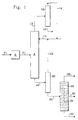
- FIG. 1 is a schematic illustration for the process arrangement. Feed is conducted via line 2 to isomerization zone 4, both of which are as described in detail above. Isomerization zone effluent is conducted via line 6 to an adsorptive separation zone 8, which is as described in detail above. Recycled and fresh desorbent, a mixture of normal butane and isobutane, is conducted to adsorptive separation zone 8 via line 15.
- the preferred mode of operation of adsorptive separation zone 8 is a simulated moving bed, however, for ease of understanding, FIG. 1 shows a simplified simulated moving bed, i.e., the rotary valve and sub-beds are not shown.
- adsorptive separation zone 8 An alternative mode of operation of adsorptive separation zone 8 is pressure swing adsorption, which may involve multiple beds (see FIG. 3 which is discussed below).
- An extract stream containing normal alkanes and desorbent is removed from adsorptive separation zone 8 via line 10.
- a raffinate stream containing isomerized products and C7+ hydrocarbons is removed from adsorptive separation zone via line 18.
- the extract stream in line 10 is passed to an extract debutanizer column 12 and a desorbent stream 14 is separated from an extract product stream 16 by fractionation.
- Extract product stream 16 contains normal pentane and normal hexane and may be recycled to the isomerization zone 4 for the production of more desired components.
- Desorbent stream 14 may be combined with line 15 and recycled to adsorptive separation zone 8.
- the raffinate stream in line 18 is passed to a raffinate debutanizer column and a desorbent stream 22 is separated from a raffinate product stream 24 by fractionation.
- the desorbent stream 22 may be combined with line 15 and recycled to adsorptive separation zone 8.
- the raffinate product line 24 is introduced at the mid-section of the left-hand side, or first fractionation zone, of dividing wall fractionation column 26 having diving wall 34.
- the dimethylbutanes and isopentane along with a portion of the monomethylpentanes are driven upward in the first fractionation zone and enter the top of column 26.
- a stream rich in dimethylbutanes and isopentane is removed from the top of the dividing wall column 26 in line 28.
- Line 28 may be passed through an overhead condenser (not shown) to form liquid delivered to the receiver.
- a liquid phase stream is removed from the receiver and divided into a first portion which is returned to the top of the dividing wall fractionation column as reflux and a second portion which is removed from the process (not shown).
- Methylcyclopentane, cyclohexane, and C 7 + compounds and some monomethylpentanes drain down the first fractionation zone and enter the bottom of column 26.
- the monomethylpentanes are driven up into the second fractionation section.
- a stream rich in methylcyclopentane, cyclohexane, and C 7 + compounds is removed from the bottom of the dividing wall column 26 in line 32.
- a stream containing 2-methylpentane and 3-methylpentane is withdrawn from the dividing wall fractionation column in a side draw from the right-hand side, or second, fractionation zone in line 30.
- the monomethylpentanes in line 30 may be recycled to the isomerization zone for isomerization into components having a higher octane value.
- the stream in line 28 may be combined with the stream in line 32 to form the overall isomerization process high-octane product.
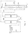
- FIG. 2 is a schematic illustration for the process arrangement.
- Feed is conducted via line 102 to isomerization zone 104, both of which are as described above.
- Isomerization zone effluent is conducted via line 106 to an adsorptive separation zone 108, which is as described above.
- Recycled (in line 113 ) and fresh desorbent (in line 115 ) is conducted to adsorptive separation zone 108 via line 113.
- the preferred mode of operation of adsorptive separation zone 108 is a simulated moving bed, however, for ease of understanding, FIG.
- FIG. 2 shows a simplified simulated moving bed, i.e., the rotary valve and sub-beds are not shown.
- An extract stream containing normal alkanes and desorbent is removed from adsorptive separation zone 108 via line 110.
- a raffinate stream containing isomerized products and C7+ hydrocarbons is removed from adsorptive separation zone via line 118.
- Integrated fractionation column 109 contains two parallel fractionation zones separated in the column by a substantially fluid tight vertical wall 111.
- the vertical wall is not necessarily centered in the column.
- Vertical wall 111 divides a large portion of column 109 into two parallel fractionation zones. The two zones are isolated from each other for the height of this wall and also at the bottom of the wall. This seal at the bottom of the first zone distinguishes the column from a true dividing wall column, hence the term integrated fractionation column.
- the upper end of the fractionation zone receiving the raffinate stream is, however, open to the internal volume of column 109. Thus vapor and liquid can freely move between these two portions of the column.
- Extract stream 110 from adsorptive separation zone 108 will contain desorbent and normal paraffins, specifically normal pentane and normal hexane.
- Raffinate stream 118 from adsorptive separation zone 108 will contain isomerization products such as methylpentane, 2-methylpentane, 3-methylpentane, methylcyclopentane, cyclohexane, isopentane, 2,2,-dimethylbutane, 2,3-dimethylbutane, C 7 + and other trace compounds.
- Both extract stream 110 and raffinate stream 118 are directed to integrated fractionation column 109. The raffinate stream is introduced to the fractionation zone occupying portions of the right-hand side of the integrated fractionation column.
- This fractionation zone is separated from the other by substantially fluid tight vertical wall 111.
- the upper end of the fractionation zone receiving the raffinate stream is open to the internal volume of column 109. Thus, vapor or liquid can freely move between the two portions of the column.
- the more volatile desorbent components of raffinate stream 118 are fractionated upward out of the fractionation zones and emerge into the upper portion of column 109.
- the less volatile raffinate components, e.g., the branched paraffins are concentrated into a bottoms stream and removed from the first fractionation zone as the raff nate product in line 124.
- extract stream 110 is delivered to a second vertical fractionation zone occupying a large portion of the left-hand side of column 109.
- the less volatile extract components, the normal pentane and normal hexane, are concentrated into a bottoms stream and removed from the first fractionation zone as the extract product via line 116.
- the upper end of the second zone is in open communication with the upper section of column 109 which contains additional fractionation trays extending across the entire column cross section.
- Desorbents present in extract stream 110 are driven upward in the second fractionation zone and enter the top of fractionation column 109.
- the top of column 109 is a purification zone which is not intended for the separation of extract or raffinate compounds from the desorbent.
- This section may be used in the present embodiment to adjust the ratio of normal butane to isobutane to the desired ratio for the desorbent function.
- a stream of liquid phase desorbent in the desired ratio of normal butane to isobutane is removed from column 109 in line 113 and may be recycled to adsorptive separation zone 108.
- a vapor stream comprising desorbents 117 is removed from the top of column 109 and is passed through an overhead condenser 119 to form liquid desorbent which may be removed from condenser via line 121 and a portion of which may be recycled to the column for reflux.
- Each of the first and second fractionation zones has independent reboiler systems (not shown).
- integrating the traditional distillation columns, one for the extract stream and one for the raffinate stream into a single integrated distillation column significantly reduces the necessary capital investment.
- the overhead system for each of the traditional distillation columns is combined into a single overhead system on the integrated distillation column, thereby reducing capital and operational costs.
- the extract product in line 116 may be recycled to the isomerization zone for conversion of the normal alkanes to higher octane isomerized products.
- the raffinate product line 124 is introduced to the dividing wall fractionation column 126 having dividing wall 134 as described in the above embodiment to form a 2-methylpentane and 3-methylpentane stream in line 130 which is removed from an intermediate point of the second fractionation zone of the dividing wall fractionation column 126; a 2,2-dimethylbutane, 2,3-dimethylpentane, and isopentane stream in line 128 which is removed from a first end of the dividing wall fractionation column 126, and a methylcyclopentane, cyclohexane, and C7+ hydrocarbons stream in line 132 which is removed from a second end of the dividing wall fractionation column 126.
- FIG. 3 An embodiment of the invention, employing pressure swing adsorption, may by exemplified by FIG. 3.
- Feed is conducted via line 202 to isomerization zone 204, both of which are as described in detail above.
- Isomerization zone effluent is conducted via line 206 to an adsorptive separation zone 208, which is a pressure swing adsorption zone having bed 208a and 208b.
- Pressure swing adsorption is a known technique, and any known pressure swing operation may be used herein.
- Fig. 3 depicts the flow scheme at one point in time. It is readily understood by one skilled in the art that pressure swing operation would require that periodically a stream is redirected from the sub-bed actively performing a separation to a sub-bed that has been regenerated and vice versa. Similarly, the effluent of each sub-bed may be periodically redirected.
- Fig. 3 is depicting sub-bed 208b as the bed actively separating, and sub-bed 208a as the bed
- Isomerization zone effluent is conducted via line 206 to adsorptive separation zone sub-bed 208b where normal alkanes are adsorbed.
- An isomerized product stream containing isomerized products and C7+ hydrocarbons is removed from adsorptive separation zone sub-bed 208b via line 210.
- the isomerized product stream may contain a small amount of regenerant as well.
- the isomerized product line 210 is introduced at the mid-section of the left-hand side, or first fractionation zone, of dividing wall fractionation column 226.
- the dimethylbutanes and isopentane along with a portion of the monomethyl pentanes are driven upward in the first fractionation zone and enter the top of column 226.
- a stream rich in dimethylbutanes and isopentane is removed from the top of the dividing wall column 226 in line 228.
- Line 228 may be passed through an overhead condenser (not shown) to form liquid delivered to the receiver.
- a liquid phase stream is removed from the receiver and divided into a first portion which is returned to the top of the dividing wall fractionation column as reflux and a second portion which is removed from the process (not shown).
- Methylcyclopentane, cyclohexane, and C 7 + compounds and some monomethylpentanes drain down the first fractionation zone and enter the bottom of column 226.
- the monomethylpentanes are driven up into the second fractionation section.
- a stream rich in methylcyclopentane, cyclohexane, and C 7 + compounds is removed from the bottom of the dividing wall column 226 in line 232.
- a stream containing 2-methylpentane and 3-methylpentane is withdrawn from the dividing wall fractionation column in a side draw from the right-hand side, or second, fractionation zone in line 230.
- the monomethylpentanes in line 230 are directed to the pressure swing adsorptive separation zone 208 for use as a regenerant.
- Line 230 is introduced to sub-bed 208a to desorb the normal alkanes.
- the effluent of sub-bed 208a contains normal alkanes and monomethylpentanes and is recycled in line 212 to reactor zone 204 for isomerization into components having a higher octane value.
- the feed stream may be introduced at a point between the isomerization zone and the adsorptive separation zone.
- the feed stream may be introduced via line 201.
- the stream in line 228 may be combined with the stream in line 232 to form the overall isomerization process product.
Landscapes
- Chemical & Material Sciences (AREA)
- Organic Chemistry (AREA)
- Engineering & Computer Science (AREA)
- Oil, Petroleum & Natural Gas (AREA)
- Analytical Chemistry (AREA)
- Water Supply & Treatment (AREA)
- Chemical Kinetics & Catalysis (AREA)
- Organic Low-Molecular-Weight Compounds And Preparation Thereof (AREA)
- Low-Molecular Organic Synthesis Reactions Using Catalysts (AREA)
- Treatment Of Liquids With Adsorbents In General (AREA)
Abstract
Description
- In many commercially important petrochemical and petroleum industry processes it is desired to separate closely boiling chemical compounds or to perform a separation of chemical compounds by structural class. It is very difficult or impossible to do this by conventional fractional distillation due to the requirement for numerous fractionation columns which may consume excessive amounts of energy. The relevant industries have responded to this problem by utilizing other separatory methods which are capable of performing a separation based upon chemical structure or characteristics. Adsorptive separation is one such method and is widely used to perform these separations.
- In the practice of adsorptive separation a feed mixture comprising two or more compounds of different skeletal structure is passed through one or more beds of an adsorbent which selectively adsorbs a compound of one skeletal structure while permitting other components of the feed stream to pass through the adsorption zone in an unchanged condition. The flow of the feed through the adsorbent bed is stopped and the adsorption zone is then flushed to remove nonadsorbed materials surrounding the adsorbent. Thereafter the desired compound is desorbed from the adsorbent by passing a desorbent stream through the adsorbent bed. The desorbent material is commonly also used to flush nonadsorbed materials from the void spaces around and within the adsorbent. This could be performed in a single large bed of adsorbent or in several parallel beds on a swing bed basis. However, it has been found that simulated moving bed adsorptive separation provides several advantages such as high purity and recovery. Therefore, many commercial scale petrochemical separations especially for specific paraffins and xylenes are performed using simulated countercurrent moving bed (SMB) technology.
- The passage of the desorbent through the adsorbent dislodges the selectively retained compounds to produce an extract stream. The extract stream contains a mixture of desorbent and the desorbed compounds, with these materials being then separated by distillation in a column referred to as the extract column. The raffinate stream contains a mixture of desorbent and the non-adsorbed compounds, with the desorbent being removed from the raffinate stream by distillation in a column referred to as the raffinate column. The subject invention is aimed at improving the ultimate product of the isomerization process through improving the fractionation employed in recovering the final desired compounds from the raffinate stream.
- Several economic advantages are derived from the continuous, as compared to batch-wise, operation of large-scale adsorptive separation processes. Recognition of this has driven the development of simulated moving bed (SMB) adsorptive separation processes. These processes typically employ a rotary valve and a plurality of lines to simulate the countercurrent movement of an adsorbent bed through adsorption and desorption zones. This is depicted, for instance, in US-A-3,205,166 and US-A-3,201,491.
- US-A-3,510,423 to R.W. Neuzil et al. provides a depiction of the customary manner of handling the raffinate and extract streams removed from an SMB process, with the desorbent being recovered, combined and recycled to the adsorption zone. US-A-4,036,745 describes the use of dual desorbents with a single adsorption zone to provide a higher purity paraffin extract. US-A-4,006,197 extends this teaching on desorbent recycling to three component desorbent mixtures.
- The dividing wall or Petyluk configuration for fractionation columns was initially introduced some 50 years ago by Petyluk et al. A recent commercialization of a fractionation column employing this technique prompted more recent investigations as described in the article appearing at page s14 of a Supplement to The Chemical Engineer, 27 August 1992.
- The use of dividing wall columns in the separation of hydrocarbons is also described in the patent literature. For instance, US-A-2,471,134 describes the use of a dividing wall column in the separation of light hydrocarbons ranging from methane to butane, US-A-4,230,533 describes a control system for a dividing wall column and illustrates the use of the claimed invention in the separation of aromatics comprising benzene, toluene and orthoxylene.
- The use of the dividing wall column in the present invention is a significant advantage over isomerization flow schemes that do not employ a dividing wall fractionation column, such as that described in Domergue, B., Watripont, L. World Refining, May 2000, p. 26-30.
- One purpose of the invention is to provide a method for separating 2-methylpentane and 3-methylpentane from a mixture containing at least 2-methylpentane, 3-methylpentane, 2,2-dimethylbutane, 2,3-dimethylpentane, isopentane, methylcyclopentane, cyclohexane, and C7+ hydrocarbons. The mixture is introduced into a dividing wall fractionation column operated at fractionation conditions and divided into at least a first and a second parallel fractionation zone by a dividing wall, with the first and the second fractionation zones each having an upper and a lower end located within the fractionation column, with the first and second fractionation zones being in open communication at their upper ends with an undivided upper section of the fractionation column and in open communication at their lower ends with an undivided lower section of the fractionation column. The mixture is introduced to the column at an intermediate point of the first fractionation zone. A stream of 2-methylpentane and 3-methylpentane is removed from an intermediate point of the second fractionation zone of the dividing wall fractionation column; a stream of, 2,2-dimethylbutane, 2,3-dimethylpentane, and isopentane, is removed from a first end of the dividing wall fractionation column, and a stream of methylcyclopentane, cyclohexane, and C7+ hydrocarbons, is removed from a second end of the dividing wall fractionation column.
- A specific embodiment of the invention provides an isomerization process having an adsorptive separation zone and a dividing wall fractionation zone. A feed stream containing at least normal pentane and normal hexane is contacted in an isomerization zone with an isomerization catalyst under isomerization conditions to convert at least a portion of the normal pentane and normal hexane into isomerized products and form an isomerization zone effluent containing normal pentane, normal hexane and isomerized products. This effluent is passed to an adsorptive separation zone comprising a bed of a selective adsorbent maintained at adsorption conditions under which the normal pentane and normal hexane are selectively retained on a quantity of the selective adsorbent, thus forming an isomerized product stream containing at least the isomerized products. The normal pentane and normal hexane are desorbed under desorption conditions to yield a normal alkane stream of at least normal pentane and normal hexane. The isomerized product stream is passed into a dividing wall fractionation column operated at fractionation conditions and divided into at least a first and a second parallel fractionation zone by a dividing wall, with the first and the second fractionation zones each having an upper and a lower end located within the fractionation column, with the first and second fractionation zones being in open communication at their upper ends with an undivided upper section of the fractionation column and in open communication at their lower ends with an undivided lower section of the fractionation column. The isomerized product stream is introduced at an intermediate point of the first fractionation zone. A low-octane stream of 2-methylpentane and 3-methylpentane is removed from an intermediate point of the second fractionation zone of the dividing wall fractionation column. A first high-octane stream is removed from a first end of the dividing wall fractionation column, and a second high-octane stream is removed from a second end of the dividing wall fractionation column.
-
- FIG. 1 is a highly simplified process flow diagram of the invention showing the raffinate stream recovered from a simulated moving bed adsorptive separation zone with the raffinate product being passed to a single dividing wall product recovery column to separate and recover the high-octane components.
- FIG. 2 is a simplified process flow diagram of the invention showing the raffinate stream and the extract stream from a simulated moving bed adsorptive separation zone entering an integrated fractionation zone to remove desorbent and form a raffinate product that passes to a single dividing wall product recovery column to separate and recover the high-octane components.
- FIG. 3 is a highly simplified process flow diagram of the invention where the adsorptive separation zone is operated in a pressure swing adsorption mode and the less strongly adsorbed isomerized products pass to a single dividing wall product recovery column to separate and recover the high-octane components.
-
- The invention is not restricted to any particular type of isomerization zone or adsorption zone, however the improvement is found in the particular downstream processing of the isomerized products stream (or raffinate), and in another embodiment, both the extract and the raffinate.
- The isomerization zone can consist of any type of isomerization zone that takes a stream of C5 to C6 straight chain hydrocarbons or a mixture of straight chain and branched chain hydrocarbons and converts straight chain hydrocarbons in the feed mixture to branched chain hydrocarbons and branched chain hydrocarbons to more highly branched chain hydrocarbons thereby producing an effluent having branched chain and straight chain hydrocarbons. In liquid phase operation, the adsorption section is preferably a simulated moving bed, although other schemes for contacting the adsorbent with the feed mixture and desorbing the feed mixture from the adsorbent with the desorbent material may be utilized. In vapor phase operation, the adsorption section may be chosen to be a pressure swing adsorption system, although other adsorptive separation modes could be successfully used.
- Suitable feedstocks for the isomerization zone will include C5 and C6 hydrocarbons, and will include at least normal hexane and normal pentane. The typical feed for this process will be a naphtha feed with an initial boiling point in the range of normal butane. The feedstocks that can be used for this invention include hydrocarbon fractionations rich in C4 to C6 normal paraffins. The term "rich" is defined as having a stream having more than 50% of the mentioned component. Useful feedstocks include light natural gasoline, light straight-run naphtha, gas oil condensates, light raffinates, light reformate, light hydrocarbons, and straight-run distillates having distillation end points of 77ºC (170ºF) and containing substantial quantities of C4 to C6 paraffins. The feed may also contain low concentrations of unsaturated hydrocarbons and hydrocarbons having more than 6 carbon atoms. The concentrations of these materials should be limited to 10 wt. % for unsaturated compounds and 20 wt. % for heavier hydrocarbons in order to restrict hydrogen consumption in cracking reactions. The feed and any normal paraffin recycle are combined and typically enter the isomerization zone with a hydrogen stream. In an alternative embodiment, the feed stream may be introduced to the adsorptive separation zone first to separate and remove any branched hydrocarbons with the normal hydrocarbons being recycled to the isomerization zone.
- Hydrogen is admixed with the feed to the isomerization zone in an amount that will provide a hydrogen to hydrocarbon molar ratio of from 0.01 to 10 in the effluent from the isomerization zone. Preferably, the hydrogen to hydrocarbon molar ratio is in the range of 0.05 to 5. Although no net hydrogen is consumed in the isomerization reaction, the isomerization zone will have a net consumption of hydrogen often referred to as the stoichiometric hydrogen requirement which is associated with a number of side reactions that occur. These side reactions include saturation of olefins and aromatics, cracking and disproportionation. For feeds having a high level of unsaturates, satisfying the stoichiometric hydrogen will require a higher hydrogen to hydrocarbon molar ratio for the feed at the inlet of the isomerization zone. Hydrogen in excess of the stoichiometric amounts for the side reactions is often maintained in the reaction zone to provide stability and conversion by compensating for variation in feed stream compositions that alter the stoichiometric hydrogen requirements. Higher hydrogen to hydrocarbon molar ratios are often used to prolong catalyst life by suppressing side reactions such as cracking and disproportionation. When such side reactions occur, they can reduce conversion and lead to formation of carbonaceous compounds, usually referred to as coke, that foul the catalyst.
- It has been found that the hydrogen to hydrocarbon ratio in isomerization zones that use a chlorided platinum alumina catalyst can be reduced significantly. In such cases, it is desirable to reduce the amount of hydrocarbon that enters the isomerization zone such that the hydrogen to hydrocarbon molar ratio of the effluent from the isomerization zone is less than 0.05.
- When the hydrogen to hydrocarbon molar ratio exceeds 0.05, it is not economically desirable to operate the isomerization zone without the recycle of hydrogen to the isomerization zone. Therefore, in such cases, recovery facilities for hydrogen from the effluent will be provided as hereinafter described.
- The hydrogen and hydrocarbon feed mixture is contacted in the reaction zone with an isomerization catalyst. The catalyst composites that can be used in the isomerization zone include traditional isomerization catalysts. Such catalysts include high chloride catalyst on an alumina base containing platinum, and crystalline aluminosilicates or crystalline zeolites. Suitable catalyst compositions of this type will exhibit selective and substantial isomerization activity under the operating conditions of the process.
- The preferred isomerization catalyst for this invention is a chlorided platinum alumina catalyst. The alumina is preferably an anhydrous gamma-alumina with a high degree of purity. The catalyst may also contain other platinum group metals. The term "platinum group metals" refers to noble metals excluding silver and gold which are selected from the group consisting of platinum, palladium, germanium, ruthenium, rhodium, osmium, and iridium. These metals demonstrate differences in activity and selectivity such that platinum has now been found to be the most suitable for this process. The catalyst will contain from 0.1 to 0.25 wt.% of the platinum. Other platinum group metals may be present in a concentration of from 0.1 to 0.25 wt.%. The platinum component may exist within the final catalytic composite as an oxide or halide or as an elemental metal. The presence of the platinum component in its reduced state has been found most suitable for this process. The chloride component termed in the art "a combined chloride" is present in an amount from 2 to 15 wt.% based upon the dry support material. The use of chloride in amounts greater than 5 wt.% have been found to be the most beneficial for this process. The inorganic oxide preferably comprises alumina and more preferably gamma-alumina, eta-alumina, and mixtures thereof.
- It is generally known that high chlorided platinum-alumina catalysts of this type are highly sensitive to sulfur and oxygen-containing compounds. Therefore, the use of such catalysts requires that the feedstock be relatively free of such compounds. A sulfur concentration no greater than 0.5 ppm is generally required. The presence of sulfur in the feedstock serves to temporarily deactivate the catalyst by platinum poisoning. Activity of the catalyst may be restored by hot hydrogen stripping of sulfur from the catalyst composite or by lowering the sulfur concentration in the incoming feed to below 0.5 ppm so that the hydrocarbon will desorb the sulfur that has been adsorbed on the catalyst. Water can act to permanently deactivate the catalyst by removing high activity chloride from the catalyst and replacing it with inactive aluminum hydroxide. Therefore, water, as well as oxygenates, in particular C1-C5 oxygenates, that can decompose to form water, can only be tolerated in very low concentrations In general, this requires a limitation of oxygenates in the feed to 0.1 ppm or less.
- As a class, the crystalline aluminosilicate or crystalline zeolite catalysts comprise crystalline zeolitic molecular sieves having an apparent pore diameter large enough to adsorb neopentane. A silica alumina molar ratio SiO2:Al2O3 of greater than 3, less than 60 and preferably between 15 and 30 is desirable In preferred form, the zeolite will contain an equivalent percentage of alkali metal cations and will have those AlO4-tetrahedra not associated with alkali metal cations, either not associated with any metal cations or associated with divalent or other polyvalent metal cations. Usually the molecular sieve is a mordenite molecular sieve which is essentially in the acid form or is converted to the acid form. Particularly preferred catalysts of this type for isomerization are disclosed in detail in US-A-3,442,794 and US-A-3,836,597.
- A preferred composition of zeolitic catalyst for use in the present invent on comprises a Group VIII noble metal, a hydrogen form crystalline aluminosilicate, and a refractory inorganic oxide with the catalyst composition having a surface area of at least 580 m2/g. Significant improvements in isomerization performar ce are realized when the surface area of the catalytic composite is at or above 580 m2/g. A Group VIII metal is incorporated into the catalytic composite to supply a hydrogenation/dehydrogenation function and the preferred Group VIII noble metal is platinum. The Group VIII noble metal is present in an amount from 0.01 to 5% by weight of the composite and preferably in an amount of at least 0.15% by weight but not over 0.35% by weight. The zeolitic catalytic composite may also contain a catalytically effective amount of a promoter metal such as tin, lead, germanium, cobalt, nickel, iron, tungsten, chromium, molybdenum, bismuth, indium, gallium, cadmium, zinc, uranium, copper, silver, gold, tantalum, or one or more of rare earth metals and mixtures thereof. The hydrogen-formed silica alumina has either a three-dimensional or channel pore structure crystal lattice framework. The three-dimensional aluminosilicates include both synthetic and naturally occurring silica aluminas such as faujasites, which include X-type, Y-type, ultrastable-Y, and the like. L-type, omega-type, and mordenite are examples of the channel pore structure crystalline aluminosilicates. Mordenite in either naturally occurring or synthetic form is preferred, particularly with a silica to alumina ratio of at least 16:1. The hydrogen form aluminosilicate may be present in an amount within the range of 50 to 99.5 wt.%, preferably within the range of 75 to 95 wt.%, and a refractory inorganic oxide may be present in an amount within the range of from 25 to 50 wt.%.
- Operating conditions within the isomerization zone are selected to maximize the production of isomerized product from the feed components. Temperatures within the reaction zone will usually range from 40-320°C (100°-600°F). Lower reaction temperatures are generally preferred since they usually favor equilibrium mixtures of isomerized products versus normal alkanes. Lower temperatures are particularly useful in processing feeds composed of C5 and C6 alkanes where the lower temperatures favor equilibrium mixtures having the highest concentration of the most branched isoalkanes. When the feed mixture is primarily C5 and C6 alkanes, temperatures in the range of from 60º to 160ºC are preferred. Higher reaction temperatures increase catalyst activity and promote the isomerization of C4 hydrocarbons. The reaction zone may be maintained over a wide range of pressures. Pressure conditions in the isomerization of C4-C6 paraffins range from 700 to 7000 Kpag. Preferred pressures for this process are in the range of from 2000 to 3000 Kpag. The feed rate to the reaction zone can also vary over a wide range. These conditions include liquid hourly space velocities ranging from 0.5 to 12 hr.-1, however, space velocities between 1 and 6 hr.-1 are preferred. The isomerization zone will usually operate at a LHSV of 1 to 2.
- Operation of the isomerization zone with the preferred chlorided platinum-alumina catalyst also requires the presence of a small amount of an organic chloride promoter. The organic chloride promoter serves to maintain a high level of active chloride on the catalyst as low levels are continuously stripped off the catalyst by the hydrocarbon feed. The concentration of promoler in the reaction zone is typically maintained at from 30 to 300 ppm. The preferred promoter compound is perchloroethylene. Other suitable promoter compounds include oxygen-free decomposable organic chlorides such as propyldichloride, butylchloride, and chloroform to name only a few of such compounds. The need to keep the reactants dry is reinforced by the presence of the organic chloride compound which converts to hydrogen chloride. As long as the process streams are kept dry, there will be no adverse effect from the presence of hydrogen chloride.
- The isomerization zone usually includes a two-reactor system with a first stage reactor and a second stage reactor with the catalyst being distributed equally between the two reactors. It is not necessary that the reaction is carried out in two reactors but the use of two reactors confer several benefits on the process. The use of two reactors and specialized valving allows partial replacement of the catalyst system without taking the isomerization unit off stream. For the short periods of time during which replacement of catalyst may be necessary, the entire flow of reactants may be processed through only one reaction vessel while catalyst is replaced in the other. The use of two reaction zones also aids in maintaining lower catalyst temperatures. This is accomplished by having any exothermic reaction such as hydrogenation of unsaturates performed in a first reaction vessel with the rest of the reaction carried out in a final reaction vessel at more favorable temperature conditions.
- The effluent from the reactors enters a stabilizer that removes light gases and butane from the effluent (not shown). The amount of butane taken off from the stabilizer will vary depending upon the amount of butane entering the process. The stabilizer normally runs at a pressure of from 800 to 1700 Kpaa. When the isomerization zone is operated with a high hydrogen to hydrocarbon ratio, a separator is usually placed ahead of the stabilizer. A hydrogen-rich recycle gas stream is recovered from the separator and recycled for combination with the feed entering the isomerization zone. When the isomerization zone operates with very low hydrogen to hydrocarbon ratios the separator is not needed and the effluent from the isomerization zone may enter the stabilizer directly.
- The bottoms stream from the stabilizer provides an isomerization zone effluent stream comprising C5 and higher boiling hydrocarbons that include normal paraffins for recycle and branched isomerized products. The chlorides which may be present in the reaction zone will usually pose no problem for the sorbent in the adsorption zone. In normal operation, any chlorides that are present in the effluent from the isomerization zone will be removed in the overhead from the stabilizer. However, where the isomerization zone or separators downstream from the isomerization zone are subject to upsets, it may be desirable to provide a guard bed of some type to treat the stabilizer bottoms and prevent any carryover of chloride compounds into the adsorption section.
- The isomerization effluent is taken by line 6 and enters the
adsorptive separation zone 8 where it is contacted with an adsorbent. It is expected that the isomerization effluent will contain compounds such as normal pentane, normal hexane, methylpentane, 2-methylpentane, 3-methylpentane, methylcyclopentane, C7+, isopentane, 2,2-dimethylbutane, 2,3-dimethylbutane, perhaps some butane and butanes, and trace other compounds. The adsorption section of this invention is operated to primarily remove the normal pentane and normal hexane fraction from the effluent of the isomerization zone. This process is especially suited for adsorption systems that use multiple ports for supplying the process streams to the adsorbent and divide the adsorbent into a plurality of zones for adsorbing normal paraffins, recovering isoparaffins, purifying the adsorbent, and desorbing the normal paraffins. A well-known process of this type is the simulated countercurrent moving bed system for simulating moving bed countercurrent flow systems as described earlier. Additional details on the operation of a typical adsorption zone in an isomerization application may be found in US-A-5,043,525 hereby incorporated by reference in its entirety. - Although much of the description herein is set in terms of use of the invention in an SMB process, the invention is believed applicable to other modes of performing adsorptive separation such as a swing bed system employing one or more separate beds of adsorbent. The greatest benefit of the present inventior is as applied to an adsorptive separation process that produces a stream comprising three compounds that are to be separated by fractionation. An example is provided below describing a specific embodiment of the invention that employs a pressure swing adsorption zone. Another variation in the simulated moving bed performance of the process is the replacement of the rotary valve with a manifold system of valves. Such systems have been described in the art such as US-A- 4,434,051, and become more practical as the number of sub-beds of adsorbent decreases.
- A number of specially defined terms are commonly used in describing the simulated moving bed processes. The term "feed stream" indicates a stream in the process through which feed material passes to the molecular sieve. A feed material comprises one or more extract components and one or more raffinate components. An "extract component" is a compound or type of compound that is more selectively retained by the molecular sieve while a "raffinate component" is a compound or type of compound that is less selectively retained. In this process normal hydrocarbons from the feed stream are extract components while isomerized products and feed stream branched chain and cyclic hydrocarbons are raffinate components. The term "displacement fluid" "or desorbent" shall mean generally a material capable of displacing an extract component. The term "desorbent" or "desorbent input stream" indicates the stream through which desorbent passes to the molecular sieve. The term "raffinate stream" or "raffinate output stream" means a stream through which most of the raffinate components are removed from the molecular sieve. The composition of the raffinate stream can vary from 100% desorbent to essentially 100% raffinate components. The term "extract stream" or "extract output stream" means a stream through which an extract material which has been displaced by a desorbent is removed from the molecular sieve. The composition of the extract stream can also vary from 100% desorbent to essentially 100% extract components.
- Desorbent is also introduced to
adsorptive separation zone 8 vialine 15. For this specific embodiment, the preferred desorbent is a mixture of normal butane and isobutane. The ratio of normal butane to isobutane in a desorbent mixture preferably is in the range of from 80:20 to 95:5. As anoption line 15 and line 6 may be combined and fed to theadsorptive separation section 8 in combination. However, it is preferred to introduce the desorbent in a separate stream so as to control the location of the desorbent input into the simulated moving bed. - Operating conditions for adsorption include, in general, a temperature range of from 20 to 250°C, with from 60 to 200°C being preferred. Temperatures from 90°C to 160°C are highly preferred for the second adsorption zone. Adsorpt on conditions also preferably include a pressure sufficient to maintain the process fluids in liquid phase; which may be from atmospheric to 600 psig. Desorption conditions generally include the same temperatures and pressure as used for adsorption conditions. It is generally preferred that an SMB process is operated with an A:F flow rate through the adsorption zone in the broad range of 1:1 to 5:1.0 where A is the volume rate of "circulation" of selective pore volume in the adsorbent and F is the feed flow rate. The practice of the subject invention requires no significant variation in operating conditions, adsorbent or desorbent composition within the adsorbent chambers. That is, the adsorbent preferably remains at the same temperature throughout the process.
- The success of a particular adsorptive separation is determined by many factors. Predominant in these factors are the composition of the adsorbent (stationary phase) and desorbent (mobile phase) employed in the process. The remaining factors are basically related to process conditions.
- The subject process is not believed to be limited to use with any particular form of adsorbent. The adsorbents employed in the process preferably comprise a molecular sieve such as a type A, X or Y zeolite or silicalite. Silicalite is well described in the literature. It is disclosed and claimed in US-A-4,061,724 issued to Grose et al. A more detailed description is found in the article, "Silicalite, A New Hydrophobic Crystalline Silica Molecular Sieve," Nature, Vol. 271, Feb. 9, 1978 which is incorporated herein by reference for its description and characterization of silicalite. Silicalite is a hydrophobic crystalline silica molecular sieve having intersecting bent-orthogonal channels formed with two cross-sectional geometries, 6Å circular and 5.1-5.7 Å elliptical on the major axis. A wide number of adsorbents are known and a starting molecular sieve is often treated by ion exchange or steaming etc to adjust its adsorptive properties. Adsorbents based upon zeolites X and Y are described in more detail in US-A-3,663,638; US-A-3,626,020 and US-A-3,997,620.
- The active component of the adsorbents is normally used in the form of particle agglomerates having high physical strength and attrition resistance. The agglomerates contain the active adsorptive material dispersed in an amorphous, inorganic matrix or binder, having channels and cavities therein which enable fluid to access the adsorptive material. Methods for forming the crystalline powders into such agglomerates include the addition of an inorganic binder, generally a clay comprising a silicon dioxide and aluminum oxide, to a high purity adsorbent powder in a wet mixture. The binder aids in forming or agglomerating the crystalline particles. The blended clay-adsorbent mixture may be extruded into cylindrical pellets or formed into beads which are subsequently calcined in order to convert the clay to an amorphous binder of considerable mechanical strength. The adsorbent may also be bound into irregular shaped particles formed by spray drying or crushing of larger masses followed by size screening. The adsorbent particles may thus be in the form of extrudates, tablets, spheres or granules having a desired particle range, preferably from 1.9 mm to 250 microns (16 to 60 mesh (Standard U.S. Mesh)). Clays of the kaolin type, water permeable organic polymers or silica are generally used as binders.
- The active molecular sieve component of the adsorbents will ordinarily be in the form of small crystals present in the adsorbent particles in amounts ranging from 75 to 98-wt.% of the particle based on volatile-free composition. Volatile-free compositions are generally determined after the adsorbent has been calcined at 900°C in order to drive off all volatile matter. The remainder of the adsorbent will generally be the inorganic matrix of the binder present in intimate mixture with the small particles of the silicalite material. This matrix material may be an adjunct of the manufacturing process for the silicalite, for example, from the intentionally incomplete purification of the silicalite during its manufacture.
- Those skilled in the art will appreciate that the performance of an adsorbent is often greatly influenced by a number of factors not related to its composition such as operating conditions, feed stream composition and the water content of the adsorbent. The optimum adsorbent composition and operating conditions for the process are therefore dependent upon a number of interrelated variables. One such variable is the water content of the adsorbent which is expressed herein in terms of the recognized Loss on Ignition (LOI) test. In the LOI test the volatile matter content of the zeolitic adsorbent is determined by the weight difference obtained before and after drying a sample of the adsorbent at 500°C under an inert gas purge such as nitrogen for a period of time sufficient to achieve a constant weight. For the subject process it is preferred that the water content of the adsorbent results in an LOI at 900°C of less than 7.0% and preferably within the range of from 0 to 4.0 wt.%. As the process fluids may dry the adsorbent, the hydration level of the sieve is normally controlled by controlled water injection, as via the desorbent stream.
- Further details on equipment and techniques for use in an SMB process may be found in US-A-3,208,833; US-A-3,214,247; US-A-3,392,113; US-A-3,455,815; US-A-3,523,762; US-A-3,617,504; US-A-3,686,342; US-A-4,006,197; US-A-4,133,842; US-A-4,434,051 and US-A-5,177,295. A different type of simulated moving bed operation which can be performed using similar equipment, adsorbent and conditions but which simulates cocurrent flow of the adsorbent and liquid in the adsorption chambers is described in US-A-4,402,832 and US-A-4,498,991.
- It has become customary in the art to group the numerous beds in the SMB adsorption chamber(s) into a number of zones. Usually the process is described in terms of 4 or 5 zones. The first contact between the feed stream and the adsorbent is made in Zone I, the adsorption zone. The adsorbent or stationary phase in Zone I becomes surrounded by liquid which contains the undesired isomer(s), that is, with raffinate. This liquid is removed from the adsorbent in Zone II, referred to as a purification zone. In the purification zone the undesired raffinate components are flushed from the void volume of the adsorbent bed by a material which is easily separated from the desired component by fractional distillation. In Zone III of the adsorbent chamber(s) the desired isomer is released from the adsorbent by exposing and flushing the adsorbent with the desorbent (mobile phase). The released desired component and accompanying desorbent are removed from the adsorbent in the form of the extract stream. Zone IV is a portion of the adsorbent located between Zones I and III which is used to segregate Zones I and III. In Zone IV desorbent is partially removed from the adsorbent by a flowing mixture of desorbent and undesired components of the feed stream. The liquid flow through Zone IV prevents contamination of Zone III by Zone I liquid by flow cocurrent to the simulated motion of the adsorbent from Zone III toward Zone I. A more thorough explanation of simulated moving bed processes is given in the Adsorptive Separation section of the Kirk-Othmer Encyclopedia of Chemical Technology at page 563. The terms "upstream" and "downstream" are used herein in their normal sense and are interpreted based upon the overall direction in which liquid is flowing in the adsorbent chamber. That is, if liquid is generally flowing downward through a vertical adsorbent chamber, then upstream is equivalent to an upward or higher location in the chamber.
- The extract stream is directed to an extract fractionation column where an extract product comprising primarily normal pentane and normal hexane is separated from the desorbent which is a mixture of normal butane and isobutane. A desorbent drag stream may be removed from the fractional distillation column in order to control the ratio of isobutane to normal butane in a desorbent which is recycled to the selective adsorptive separation section. The desorbent drag stream may be employed to remove any excess desorbent components which enter the adsorptive system as part of the feed. It is also feasible to withdraw the drag stream from the raffinate fractionation column in some circumstances. The extract fractionation column typically operates in the range of from 90 to 160°C, with the temperature being measured at the bottoms of the column, and from 340 to 1030 Kpag, with from 40 to 60 trays. The separated desorbent may be recycled to the adsorptive separation zone and the separated extract product stream may be recycled to the isomerization zone.
- The raffinate stream from the adsorptive separation zone is directed to a raffinate fractionation column to separate desorbent from isomerized products. Desorbent is removed from the overhead and may be combined with the overhead desorbent from the extract fractionation column and the collective recovered desorbent may be recycled to the adsorptive separation zone. The raffinate product stream is withdrawn from the bottom of the raffinate fractionation column and contains primarily 2,3-dimethylbutane, 2,2-dimethylbutane, isopentane, 2-methylpentane, 3-methylpentane, methylcyclopentane, cyclohexane and C7+. The raffinate fractionation column typically operates in the range of from 90 to 160°C, with the temperature being measured at the bottoms of the column, and from 340 to 1030 Kpag, with from 40 to 60 trays.
- The raffinate product stream is directed to an octane enhancement zone having a dividing wall fractional distillation column. Within the dividing wall fractional distillation column are two parallel fractionation zones. A first fractionation zone occupies a large portion of the left-hand side of the mid-section of the fractional distillation column. Note that the terms "left-hand" and "right-hand" are used herein as relative to the drawings. In actual practice the placement of the zones as to the left side or the right side of the column is not critical. This first fractionation zone is separated from a parallel second fractionation zone occupying the other half of the column cross section by a substantially fluid tight vertical wall. The vertical wall is not necessarily centered in the column and the two fractionation zones may differ in cross sectional area or shape. The vertical wall divides a large vertical portion of the column into two parallel fractionation zones. The two zones are isolated from each other for the height of this wall, but communicate at both the top and bottom ends of the column. There is no direct vapor or liquid flow between the two fractionation zones through the dividing wall, but the upper end of the fractionation zone receiving the raffinate product is open to the internal volume of the distillation column containing an undivided fractionation zone preferably having additional trays. Liquid may pass under the dividing wall at the bottom of the two fractionation sections although vapor flow is preferably restricted. Thus, vapor and liquid can freely move around the wall between the two portions of the column. During operation, the raffinate product is separated in the first fractionation zone with the more volatile compounds moving upward out of the left-hand first fractionation zone and emerging into the undivided upper portion of the distillation column. As with the first fractionation zone, the upper end of the right-hand second zone is in open communication with the upper section of the distillation column which preferably contains additional fractionation trays extending across the entire column cross section.
- The raffinate product stream contains 2,3-dimethylbutane, 2,2-dimethylbutane, isopentane, 2-methylpentane, 3-methylpentane, methylcyclopentane, cyclohexane and C7+. For ease of discussion, the raffinate product stream components will be grouped according to boiling point, which is the main factor in determining their behavior in the factional distillation column. The components having relatively low boiling points will be labeled Group A and will consist of 2,3-dimethylbutane, 2,2-dimethylbutane, and isopentane. Group A contains high-octane components which are desired products of the overall isomerization process. The mid-range boiling components will be labeled Group B and contains 2-methylpentane and 3-methylpentane. Group B contains lower octane components that would best be recycled to the isomerization zone and not included in a final product (or used in desorbing the normal alkanes in a pressure swing adsorption zone). Separating and recycling the 2-methylpentane and 3-methylpentane results in the final product having a higher overall octane value. The components having relatively high boiling points will be labeled Group C and will consist of methylcyclopentane, cyclohexane, and C7+. Group C also contains high-octane components and are desired products of the overall isomerization process. The combination of Group A and Group C forms the final high-octane isomerization process product.
- The raffinate product stream from the raffinate column is introduced into a first vertical fractionation zone occupying a large portion of the left-hand side of the midsection of the fractional distillation column. The Group A components along with a portion of the Group B components present in the raffinate stream are driven upward in the first fractionation zone and enter the top of the column. The top of the column is a purification zone which is designed to separate the Group A components from the group B components. A Group A-rich stream is removed from the top of the dividing wall and passed through an overhead condenser (not shown) to form liquid delivered to the receiver. A liquid phase stream of Group A components is removed from the receiver and divided into a first portion which is returned to the top of the dividing wall fractionation column as reflux and a second portion which is removed from the process. As used herein the term "rich" is intended to indicate a concentration of the indicated compound or class of compounds greater than 50 and preferably greater than 75 mol percent.
- The bottom of the dividing wall column also comprises an undivided fractionation zone. This zone can receive liquid draining from both the first and second fractionation zones. This liquid is subjected to fractional distillation which drives the Group B components upwards as vapor while concentrating the less volatile Group C components into a bottoms liquid that is removed from the dividing wall fractionation column. This separation is effected through the use of a reboiler (not shown) providing vapor to the bottom undivided fractionation zone. The Group C-rich bottoms liquid is combined with the Group A rich stream from the top of the column to form the overall isomerization process high-octane product. The Group B components are withdrawn from the dividing wall fractionation column in a side draw from the right-hand side fractionation zone. The Group B components may be recycled to the isomerization zone for isomerization into components having a higher octane value.
- In a more specific embodiment of the invention, the undivided bottom section of the dividing wall fractionation column is depicted as separated from the two parallel fractionation zones by a gas flow control or gas trap out tray located just below the bottom of the wall. A slight gap at this point allows horizontal liquid flow between the parallel fractionation zones. This tray may have liquid sealed perforations allowing the normal downward flow of liquid, but its structure is such that the upward flow of vapor is at least greatly restricted. The tray may totally block the upward vapor flow. The use of this tray is preferred as it provides a means to positively control the division of the upward gas flow between the two fractionation zones, which is a prime means of controlling performance of the two zones. The total vapor flow is, therefore, preferably removed from the column via a line and divided between two separate lines which feed the vapor to the bottom of the two parallel fractionation zones. The gas flow may be controlled by one or more flow control valves or by adjusting the relative liquid levels in the bottom of the two zones. This is described in some detail in previously cited US-A-4,230,533 for a slightly different arrangement.
- A representative comparison of the separation as shown in FIG. 1 based upon engineering design calculations, which for the conventional case have the benefit of comparison to many operating units, indicates that a conventional fractionation column, commonly referred to as a deisohexanizer, which contains a total of 80 trays could be replaced with the dividing wall column of the present invention containing a total of 65 trays. The dividing wall column requires a total reboiling duty of 3.43 x 10⁷ BTU/hr versus 5.45 x 10⁷ BTU/hr for the conventional column. The dividing wall column requires a total condenser duty of 3.99 x 10⁷ MMBTU/hr versus 6.20 x 10⁷ for the standard column case. Therefore, the present invention, through the use of the dividing wall column reduces the capital costs as to the number of trays as well as the utility costs as compared to a conventional fractionation column.
- FIG. 1 is a schematic illustration for the process arrangement. Feed is conducted via line 2 to isomerization
zone 4, both of which are as described in detail above. Isomerization zone effluent is conducted via line 6 to anadsorptive separation zone 8, which is as described in detail above. Recycled and fresh desorbent, a mixture of normal butane and isobutane, is conducted toadsorptive separation zone 8 vialine 15. The preferred mode of operation ofadsorptive separation zone 8 is a simulated moving bed, however, for ease of understanding, FIG. 1 shows a simplified simulated moving bed, i.e., the rotary valve and sub-beds are not shown. An alternative mode of operation ofadsorptive separation zone 8 is pressure swing adsorption, which may involve multiple beds (see FIG. 3 which is discussed below). An extract stream containing normal alkanes and desorbent is removed fromadsorptive separation zone 8 vialine 10. A raffinate stream containing isomerized products and C7+ hydrocarbons is removed from adsorptive separation zone vialine 18. - The extract stream in
line 10 is passed to anextract debutanizer column 12 and adesorbent stream 14 is separated from anextract product stream 16 by fractionation.Extract product stream 16 contains normal pentane and normal hexane and may be recycled to theisomerization zone 4 for the production of more desired components.Desorbent stream 14 may be combined withline 15 and recycled toadsorptive separation zone 8. The raffinate stream inline 18 is passed to a raffinate debutanizer column and adesorbent stream 22 is separated from araffinate product stream 24 by fractionation. Thedesorbent stream 22 may be combined withline 15 and recycled toadsorptive separation zone 8. - The
raffinate product line 24 is introduced at the mid-section of the left-hand side, or first fractionation zone, of dividingwall fractionation column 26 havingdiving wall 34. The dimethylbutanes and isopentane along with a portion of the monomethylpentanes are driven upward in the first fractionation zone and enter the top ofcolumn 26. A stream rich in dimethylbutanes and isopentane is removed from the top of the dividingwall column 26 in line 28. Line 28 may be passed through an overhead condenser (not shown) to form liquid delivered to the receiver. A liquid phase stream is removed from the receiver and divided into a first portion which is returned to the top of the dividing wall fractionation column as reflux and a second portion which is removed from the process (not shown). - Methylcyclopentane, cyclohexane, and C7+ compounds and some monomethylpentanes drain down the first fractionation zone and enter the bottom of
column 26. The monomethylpentanes are driven up into the second fractionation section. A stream rich in methylcyclopentane, cyclohexane, and C7+ compounds is removed from the bottom of the dividingwall column 26 inline 32. A stream containing 2-methylpentane and 3-methylpentane is withdrawn from the dividing wall fractionation column in a side draw from the right-hand side, or second, fractionation zone inline 30. The monomethylpentanes inline 30 may be recycled to the isomerization zone for isomerization into components having a higher octane value. The stream in line 28 may be combined with the stream inline 32 to form the overall isomerization process high-octane product. - In another embodiment of the invention, the extract column and the raffinate column described above are replaced by an integrated fractionation column. FIG. 2 is a schematic illustration for the process arrangement. Feed is conducted via
line 102 toisomerization zone 104, both of which are as described above. Isomerization zone effluent is conducted vialine 106 to anadsorptive separation zone 108, which is as described above. Recycled (in line 113) and fresh desorbent (in line 115), a mixture of normal butane and isobutane, is conducted toadsorptive separation zone 108 vialine 113. The preferred mode of operation ofadsorptive separation zone 108 is a simulated moving bed, however, for ease of understanding, FIG. 2 shows a simplified simulated moving bed, i.e., the rotary valve and sub-beds are not shown. An extract stream containing normal alkanes and desorbent is removed fromadsorptive separation zone 108 vialine 110. A raffinate stream containing isomerized products and C7+ hydrocarbons is removed from adsorptive separation zone vialine 118. -
Integrated fractionation column 109 contains two parallel fractionation zones separated in the column by a substantially fluid tightvertical wall 111. The vertical wall is not necessarily centered in the column.Vertical wall 111 divides a large portion ofcolumn 109 into two parallel fractionation zones. The two zones are isolated from each other for the height of this wall and also at the bottom of the wall. This seal at the bottom of the first zone distinguishes the column from a true dividing wall column, hence the term integrated fractionation column. Thus there is no direct vapor or liquid flow between the two fractionation zones. The upper end of the fractionation zone receiving the raffinate stream is, however, open to the internal volume ofcolumn 109. Thus vapor and liquid can freely move between these two portions of the column. This opening of the top of each fractionation zone into a larger fractionation zone allows vapor from both parallel zones to flow upward. The two smaller zones are thus described as being in open communication with each other and this larger zone at this point in the column. Liquid flow downward may or may not be regulated between the zones. Both of the fractionation zones have independent reboiling means (not shown). -
Extract stream 110 fromadsorptive separation zone 108 will contain desorbent and normal paraffins, specifically normal pentane and normal hexane.Raffinate stream 118 fromadsorptive separation zone 108 will contain isomerization products such as methylpentane, 2-methylpentane, 3-methylpentane, methylcyclopentane, cyclohexane, isopentane, 2,2,-dimethylbutane, 2,3-dimethylbutane, C7+ and other trace compounds. Bothextract stream 110 andraffinate stream 118 are directed tointegrated fractionation column 109. The raffinate stream is introduced to the fractionation zone occupying portions of the right-hand side of the integrated fractionation column. This fractionation zone is separated from the other by substantially fluid tightvertical wall 111. The upper end of the fractionation zone receiving the raffinate stream is open to the internal volume ofcolumn 109. Thus, vapor or liquid can freely move between the two portions of the column. The more volatile desorbent components ofraffinate stream 118 are fractionated upward out of the fractionation zones and emerge into the upper portion ofcolumn 109. The less volatile raffinate components, e.g., the branched paraffins are concentrated into a bottoms stream and removed from the first fractionation zone as the raff nate product inline 124. - Concurrently,
extract stream 110 is delivered to a second vertical fractionation zone occupying a large portion of the left-hand side ofcolumn 109. The less volatile extract components, the normal pentane and normal hexane, are concentrated into a bottoms stream and removed from the first fractionation zone as the extract product vialine 116. As with the first fractionation zone, the upper end of the second zone is in open communication with the upper section ofcolumn 109 which contains additional fractionation trays extending across the entire column cross section. Desorbents present inextract stream 110 are driven upward in the second fractionation zone and enter the top offractionation column 109. The top ofcolumn 109 is a purification zone which is not intended for the separation of extract or raffinate compounds from the desorbent. This section may be used in the present embodiment to adjust the ratio of normal butane to isobutane to the desired ratio for the desorbent function. A stream of liquid phase desorbent in the desired ratio of normal butane to isobutane is removed fromcolumn 109 inline 113 and may be recycled toadsorptive separation zone 108. A vapor stream comprising desorbents 117 is removed from the top ofcolumn 109 and is passed through anoverhead condenser 119 to form liquid desorbent which may be removed from condenser vialine 121 and a portion of which may be recycled to the column for reflux. - Each of the first and second fractionation zones has independent reboiler systems (not shown). However, integrating the traditional distillation columns, one for the extract stream and one for the raffinate stream into a single integrated distillation column significantly reduces the necessary capital investment. Specifically, the overhead system for each of the traditional distillation columns is combined into a single overhead system on the integrated distillation column, thereby reducing capital and operational costs. The extract product in
line 116 may be recycled to the isomerization zone for conversion of the normal alkanes to higher octane isomerized products. Theraffinate product line 124 is introduced to the dividingwall fractionation column 126 having dividingwall 134 as described in the above embodiment to form a 2-methylpentane and 3-methylpentane stream inline 130 which is removed from an intermediate point of the second fractionation zone of the dividingwall fractionation column 126; a 2,2-dimethylbutane, 2,3-dimethylpentane, and isopentane stream in line 128 which is removed from a first end of the dividingwall fractionation column 126, and a methylcyclopentane, cyclohexane, and C7+ hydrocarbons stream inline 132 which is removed from a second end of the dividingwall fractionation column 126. - An embodiment of the invention, employing pressure swing adsorption, may by exemplified by FIG. 3. Feed is conducted via
line 202 toisomerization zone 204, both of which are as described in detail above. Isomerization zone effluent is conducted vialine 206 to anadsorptive separation zone 208, which is a pressure swing adsorptionzone having bed - Isomerization zone effluent is conducted via
line 206 to adsorptive separation zone sub-bed 208b where normal alkanes are adsorbed. An isomerized product stream containing isomerized products and C7+ hydrocarbons is removed from adsorptive separation zone sub-bed 208b vialine 210. The isomerized product stream may contain a small amount of regenerant as well. - The
isomerized product line 210 is introduced at the mid-section of the left-hand side, or first fractionation zone, of dividingwall fractionation column 226. The dimethylbutanes and isopentane along with a portion of the monomethyl pentanes are driven upward in the first fractionation zone and enter the top ofcolumn 226. A stream rich in dimethylbutanes and isopentane is removed from the top of the dividingwall column 226 in line 228. Line 228 may be passed through an overhead condenser (not shown) to form liquid delivered to the receiver. A liquid phase stream is removed from the receiver and divided into a first portion which is returned to the top of the dividing wall fractionation column as reflux and a second portion which is removed from the process (not shown). - Methylcyclopentane, cyclohexane, and C7+ compounds and some monomethylpentanes drain down the first fractionation zone and enter the bottom of
column 226. The monomethylpentanes are driven up into the second fractionation section. A stream rich in methylcyclopentane, cyclohexane, and C7+ compounds is removed from the bottom of the dividingwall column 226 inline 232. A stream containing 2-methylpentane and 3-methylpentane is withdrawn from the dividing wall fractionation column in a side draw from the right-hand side, or second, fractionation zone inline 230. - The monomethylpentanes in
line 230 are directed to the pressure swingadsorptive separation zone 208 for use as a regenerant.Line 230 is introduced to sub-bed 208a to desorb the normal alkanes. The effluent of sub-bed 208a contains normal alkanes and monomethylpentanes and is recycled inline 212 toreactor zone 204 for isomerization into components having a higher octane value. Alternatively, the feed stream may be introduced at a point between the isomerization zone and the adsorptive separation zone. For example, the feed stream may be introduced vialine 201. The stream in line 228 may be combined with the stream inline 232 to form the overall isomerization process product.
Claims (8)
- A process for separating 2-methylpentane and 3-methylpentane from a mixture containing at least 2-methylpentane, 3-methylpentane, 2,2-dimethylbutane, 2,3-dimethylpentane, isopentane, methylcyclopentane, cyclohexane, and C7+ hydrocarbons, the process comprising:passing the mixture into a dividing wall fractionation column operated at fractionation conditions and divided into at least a first and a second parallel fractionation zone by a dividing wall, with the first and the second fractionation zones each having an upper and a lower end located within the fractionation column, with the first and second fractionation zones being in open communication at their upper ends with an undivided upper section of the fractionation column and in open communication at their lower ends with an undivided lower section of the fractionation column, and with the mixture entering the column at an intermediate point of the first fractionation zone;removing a stream comprising 2-methylpentane and 3-methylpentane from an intermediate point of the second fractionation zone of the dividing wall fractionation column;removing a stream comprising 2,2-dimethylbutane, 2,3-dimethylpentane, and isopentane from a first end of the dividing wall fractionation column, and removing a stream comprising methylcyclopentane, cyclohexane, and C7+ hydrocarbons from a second end of the dividing wall fractionation column.
- The process of claim 1 wherein the feed streams a normal alkane stream containing at least normal pentane and normal hexane from an adsorptive separation zone contacts an isomerization catalyst in an isomerization zone under isomerization conditions to convert at least a portion of the normal pentane and normal hexane into isomerized products and form an isomerization zone effluent containing normal pentane, normal hexane and isomerized products, a feed stream containing at least normal pentane and normal hexane and the isomerization zone effluent pass to an adsorptive separation zone comprising at least one bed of a selective adsorbent maintained at adsorption conditions under which the normal pentane and normal hexane are selectively retained on a quantity of the selective adsorbent, thus forming an isomerized product stream comprising at least the isomerized products;
desorbing the normal pentane and normal hexane under desorption conditions to yield the normal alkane stream comprising at least normal pentane and normal hexane;
passing the isomerized product stream into the dividing wall fractionation column. - The process of claim 1 wherein a feed stream containing at least normal pentane and normal hexane with contacts isomerization catalyst in an isomerization zone under isomerization conditions to convert at least a portion of the normal pentane and normal hexane into isomerized products and form an isomerization zone effluent containing normal pentane, normal hexane and isomerized products, the isomerization zone effluent passes to an adsorptive separation zone comprising at least one bed of a selective adsorbent maintained at adsorption conditions under which the normal pentane and normal hexane are selectively retained on a quantity of the selective adsorbent, thus forming an isomerized product stream comprising the mixture and containing at least the isomerized products, the normal pentane and normal hexane under desorption conditions to yield a normal alkane stream comprising at least normal pentane and normal hexane.
- The process of claim 3 wherein process comprising:the isomerized product stream is recovered as a raffinate stream comprising the isomerized products and desorbent formerly present in the quantity of the selective adsorbent, a desorbent into contact with said quantity of the selective adsorbent which has retained the normal pentane and normal hexane under desorption conditions to yield an extract stream comprising normal pentane, normal hexane, and the desorbent, the extract stream passes into an integrated fractionation column operated at fractionation conditions and divided into at least a first and a second vertical fractionation zone, with each zone having an upper and a lower end located within the fractionation column, with the first and second fractionation zones being in open communication at their upper ends at a first end of the column and with the extract stream entering the fractionation column at an intermediate point of the first fractionation zone;the raffinate stream passes into an intermediate point of the second fractionation zone of the integrated fractionation column;an extract product stream is removed from a first end of the first fractionation zone, said first end not being in communication with the second fractionation zone and being located at the second end of the integrated fractionation column, a raffinate product stream is removed from a first end of the second fractionation zone, said first end not being in communication with the first fractionation zone and being located at the second end of the integrated fractionation column;a desorbent stream is recovered comprising the desorbent from the first end of the integrated fractionation column, and the raffinate product stream enters the dividing wall fractionation column.
- The process of Claims 3 or 4 wherein the adsorptive separation zone is operated in mode selected from the group consisting of a simulated moving bed mode and a pressure swing adsorption mode.
- The process of Claims 1, 2, 3 or 4 further comprising collecting upward flow of vapor from the lower section of the dividing wall fractionation column into the first and second fractionation zones and then dividing vapor between the first and second fractionation zones in a controlled manner.
- The process of Claim 3 further comprising passing the normal alkane stream to a fractionation column to separate a desorbent from the normal alkane stream and recycling the resulting desorbent-reduced normal alkane stream to the isomerization zone and passing the isomerized product stream to a fractionation column to separate the desorbent from the isomerized product stream prior to entering the dividing wall fractionation column.
- The process of Claim 4 further comprising recycling the extract product stream to the isomerization zone.
Applications Claiming Priority (2)
| Application Number | Priority Date | Filing Date | Title |
|---|---|---|---|
| US710721 | 2000-11-10 | ||
| US09/710,721 US6395950B1 (en) | 2000-11-10 | 2000-11-10 | Isomerization with adsorptive separation and dividing wall fractional distillation |
Publications (2)
| Publication Number | Publication Date |
|---|---|
| EP1205460A1 true EP1205460A1 (en) | 2002-05-15 |
| EP1205460B1 EP1205460B1 (en) | 2004-05-12 |
Family
ID=24855234
Family Applications (1)
| Application Number | Title | Priority Date | Filing Date |
|---|---|---|---|
| EP01309484A Expired - Lifetime EP1205460B1 (en) | 2000-11-10 | 2001-11-09 | Process for distillation, in a column with a dividing wall, of saturated hydrocarbons obtained by isomerisation |
Country Status (7)
| Country | Link |
|---|---|
| US (2) | US6395950B1 (en) |
| EP (1) | EP1205460B1 (en) |
| AT (1) | ATE266612T1 (en) |
| DE (1) | DE60103230T2 (en) |
| ES (1) | ES2220678T3 (en) |
| PT (1) | PT1205460E (en) |
| TR (1) | TR200401463T4 (en) |
Cited By (14)
| Publication number | Priority date | Publication date | Assignee | Title |
|---|---|---|---|---|
| FR2862311A1 (en) * | 2003-11-14 | 2005-05-20 | Inst Francais Du Petrole | PROCESS FOR PRODUCING HIGH OCTANE INDEXES FROM A C5 / C6 CUT USING A MENBRANE SEPARATION UNIT |
| US7368610B2 (en) | 2003-09-10 | 2008-05-06 | Basf Aktiengesellschaft | Preparation of xylylenediamine (XDA) |
| US7498472B2 (en) | 2007-05-23 | 2009-03-03 | Uop Llc | Process for producing ethylbenzene |
| US7498471B2 (en) | 2007-05-23 | 2009-03-03 | Uop Llc | Process for producing cumene |
| US7525005B2 (en) | 2007-05-23 | 2009-04-28 | Uop Llc | Process for producing cumene |
| US7525006B2 (en) | 2007-05-23 | 2009-04-28 | Uop Llc | Process for producing cumene |
| US7525003B2 (en) | 2007-05-23 | 2009-04-28 | Uop Llc | Process for producing ethylbenzene |
| US7525004B2 (en) | 2007-05-23 | 2009-04-28 | Uop Llc | Process for producing ethylbenzene |
| US7713386B2 (en) | 2007-05-23 | 2010-05-11 | Uop Llc | Apparatus for producing ethylbenzene or cumene |
| CN103242120A (en) * | 2013-04-27 | 2013-08-14 | 天津大学 | Circulating device and refining method of extractant in normal hexane, isohexane and benzene separation process |
| CN106397088A (en) * | 2016-09-13 | 2017-02-15 | 中国天辰工程有限公司 | High-efficiency refining method for making cyclohexanone and producing cyclohexane as by-product by cyclohexene method |
| RU2621349C1 (en) * | 2016-03-30 | 2017-06-02 | Федеральное государственное бюджетное образовательное учреждение высшего профессионального образования "Уфимский государственный нефтяной технический университет" | Method for separation of isophetic-pentan-isohexan-hexane fraction, reducing the share of recycle flows in the system |
| CN109293465A (en) * | 2018-10-12 | 2019-02-01 | 青岛科技大学 | A process for separating methylcyclopentane and cyclohexane by single-column heat pump rectification |
| WO2021113039A1 (en) * | 2019-12-05 | 2021-06-10 | Exxonmobil Research And Engineering Company | Dividing wall column separator with intensified separations |
Families Citing this family (28)
| Publication number | Priority date | Publication date | Assignee | Title |
|---|---|---|---|---|
| DE10105660A1 (en) * | 2001-02-08 | 2002-08-14 | Basf Ag | Process for the extraction of crude 1,3-butadiene by extractive distillation from a C4 cut |
| US6759563B1 (en) * | 2001-10-09 | 2004-07-06 | Uop Llc | Liquid phase adsorptive separation with hexane desorbent and paraffin isomerization |
| KR100645660B1 (en) * | 2001-11-09 | 2006-11-13 | 에스케이 주식회사 | Process for separating normal paraffin from hydrocarbon fraction and utilizing separated fraction |
| US6927314B1 (en) | 2002-07-17 | 2005-08-09 | Uop Llc | Fractionation and treatment of full boiling range gasoline |
| EP1418216A1 (en) * | 2002-11-07 | 2004-05-12 | N.V. Solutia S.A. | Heat transfer fluids for application over a broad range of temperatures |
| JP2007521217A (en) * | 2003-06-20 | 2007-08-02 | フォード モーター カンパニー | Apparatus and method for reforming VOC gas |
| US7452459B2 (en) * | 2004-03-30 | 2008-11-18 | Uop Llc | Process for the removal of sulfur-oxidated compounds from a hydrocarbonaceous stream |
| US7371912B2 (en) * | 2005-06-15 | 2008-05-13 | Uop Llc | Process for making xylene isomer using a deheptanizer with a side draw recycle |
| US7960601B2 (en) * | 2008-11-17 | 2011-06-14 | Uop Llc | Heavy paraffin adsorption separation process |
| US8273938B2 (en) | 2008-11-17 | 2012-09-25 | Uop Llc | Heavy olefin production process |
| US8246816B2 (en) * | 2009-03-04 | 2012-08-21 | Uop Llc | Zone or system for providing one or more streams |
| US8999117B2 (en) * | 2009-03-04 | 2015-04-07 | Uop Llc | Process and system for heating or cooling streams for a divided distillation column |
| US8608947B2 (en) | 2010-09-30 | 2013-12-17 | Uop Llc | Two-stage hydrotreating process |
| US8691082B2 (en) | 2010-09-30 | 2014-04-08 | Uop Llc | Two-stage hydroprocessing with common fractionation |
| US8911694B2 (en) | 2010-09-30 | 2014-12-16 | Uop Llc | Two-stage hydroprocessing apparatus with common fractionation |
| US8747654B2 (en) | 2010-12-03 | 2014-06-10 | Uop Llc | Process for recovering catalytic product |
| ITPI20110018A1 (en) * | 2011-02-21 | 2012-08-22 | Sime S R L | METHOD AND APPARATUS FOR THE SOFTENING AND / OR DEHYDRATION OF A GAS BASED ON HYDROCARBONS, IN PARTICULAR NATURAL GAS |
| MX2015010638A (en) * | 2013-02-21 | 2015-12-15 | Gtc Technology Us Llc | Separation processes using divided columns. |
| US9126875B2 (en) | 2013-06-27 | 2015-09-08 | Uop Llc | Sorption process with added drying section |
| BR112017004454B1 (en) * | 2014-09-05 | 2022-11-01 | Procept Biorobotics Corporation | APPARATUS FOR REMOVING INTACT CELLS FROM A SURGICAL AREA OF A PATIENT |
| US10106476B1 (en) * | 2017-03-31 | 2018-10-23 | David Norbert Kockler | Energy efficient methods for isomerization of a C5-C7 fraction with dividing wall fractional distillation |
| US10118875B1 (en) * | 2017-09-13 | 2018-11-06 | David Norbert Kockler | Energy efficient methods for isomerization of a C5-C6 fraction with dividing wall fractional distillation |
| PL3664906T3 (en) * | 2017-09-19 | 2023-12-04 | Sulzer Management Ag | Use of top dividing wall in isomerization unit |
| KR20220010512A (en) * | 2019-05-15 | 2022-01-25 | 술저 매니지멘트 에이지 | Purification of Hexane as a By-product of the Isomerization Unit Using a Split-Wall Column |
| CN112403013B (en) * | 2020-10-28 | 2023-01-10 | 洛阳金达石化有限责任公司 | Fine processing method of crude hexane |
| US11745116B2 (en) * | 2021-10-01 | 2023-09-05 | Manish Bhargava | Apparatus for a dividing wall column in an isomerization unit |
| US20250115537A1 (en) | 2022-01-19 | 2025-04-10 | Exxonmobil Chemical Patents Inc. | Compositions Containing Tri-Cyclopentadiene and Processes for Making Same |
| WO2025245037A1 (en) | 2024-05-20 | 2025-11-27 | Materia, Inc. | Cyclic olefin compositions, romp compositions thereof, and applications thereof |
Citations (1)
| Publication number | Priority date | Publication date | Assignee | Title |
|---|---|---|---|---|
| DE3302525A1 (en) * | 1983-01-26 | 1984-07-26 | Basf Ag, 6700 Ludwigshafen | DISTILLATION COLUMN FOR THE DISTILLATIVE DISASSEMBLY OF AN INLET PRODUCT MULTIPLE FRACTIONS |
Family Cites Families (9)
| Publication number | Priority date | Publication date | Assignee | Title |
|---|---|---|---|---|
| US2471134A (en) | 1946-07-17 | 1949-05-24 | Standard Oil Dev Co | Fractionation apparatus |
| NL293774A (en) | 1962-06-08 | |||
| US3201491A (en) | 1962-09-05 | 1965-08-17 | Universal Oil Prod Co | Continuous sorption process with emphasis on product purity |
| US3510423A (en) | 1968-04-05 | 1970-05-05 | Universal Oil Prod Co | Olefin separation process |
| US4036745A (en) | 1975-09-24 | 1977-07-19 | Uop Inc. | Process for separating normal and isoparaffins |
| US4006197A (en) | 1975-11-19 | 1977-02-01 | Uop Inc. | Process for separating normal paraffins |
| US4146462A (en) * | 1978-05-19 | 1979-03-27 | Rustamov Musa I O | Hydroisomerization of gasoline fraction |
| US4230533A (en) | 1978-06-19 | 1980-10-28 | Phillips Petroleum Company | Fractionation method and apparatus |
| US5177299A (en) * | 1991-12-30 | 1993-01-05 | Uop | Recovery of high octane components from isomerates |
-
2000
- 2000-11-10 US US09/710,721 patent/US6395950B1/en not_active Expired - Fee Related
-
2001
- 2001-09-05 US US09/947,132 patent/US6472578B1/en not_active Expired - Lifetime
- 2001-11-09 EP EP01309484A patent/EP1205460B1/en not_active Expired - Lifetime
- 2001-11-09 ES ES01309484T patent/ES2220678T3/en not_active Expired - Lifetime
- 2001-11-09 TR TR2004/01463T patent/TR200401463T4/en unknown
- 2001-11-09 DE DE60103230T patent/DE60103230T2/en not_active Expired - Lifetime
- 2001-11-09 AT AT01309484T patent/ATE266612T1/en not_active IP Right Cessation
- 2001-11-09 PT PT01309484T patent/PT1205460E/en unknown
Patent Citations (1)
| Publication number | Priority date | Publication date | Assignee | Title |
|---|---|---|---|---|
| DE3302525A1 (en) * | 1983-01-26 | 1984-07-26 | Basf Ag, 6700 Ludwigshafen | DISTILLATION COLUMN FOR THE DISTILLATIVE DISASSEMBLY OF AN INLET PRODUCT MULTIPLE FRACTIONS |
Cited By (18)
| Publication number | Priority date | Publication date | Assignee | Title |
|---|---|---|---|---|
| US7368610B2 (en) | 2003-09-10 | 2008-05-06 | Basf Aktiengesellschaft | Preparation of xylylenediamine (XDA) |
| FR2862311A1 (en) * | 2003-11-14 | 2005-05-20 | Inst Francais Du Petrole | PROCESS FOR PRODUCING HIGH OCTANE INDEXES FROM A C5 / C6 CUT USING A MENBRANE SEPARATION UNIT |
| WO2005049766A1 (en) * | 2003-11-14 | 2005-06-02 | Institut Francais Du Petrole | Method for producing a high-octane gasoline from a c5/c6 fraction by means of a membrane separation unit |
| US7525004B2 (en) | 2007-05-23 | 2009-04-28 | Uop Llc | Process for producing ethylbenzene |
| US7498471B2 (en) | 2007-05-23 | 2009-03-03 | Uop Llc | Process for producing cumene |
| US7525005B2 (en) | 2007-05-23 | 2009-04-28 | Uop Llc | Process for producing cumene |
| US7525006B2 (en) | 2007-05-23 | 2009-04-28 | Uop Llc | Process for producing cumene |
| US7525003B2 (en) | 2007-05-23 | 2009-04-28 | Uop Llc | Process for producing ethylbenzene |
| US7498472B2 (en) | 2007-05-23 | 2009-03-03 | Uop Llc | Process for producing ethylbenzene |
| US7713386B2 (en) | 2007-05-23 | 2010-05-11 | Uop Llc | Apparatus for producing ethylbenzene or cumene |
| CN103242120A (en) * | 2013-04-27 | 2013-08-14 | 天津大学 | Circulating device and refining method of extractant in normal hexane, isohexane and benzene separation process |
| CN103242120B (en) * | 2013-04-27 | 2015-11-04 | 天津大学 | Extractant circulation device and refining method in separation process of n-hexane, isohexane and benzene |
| RU2621349C1 (en) * | 2016-03-30 | 2017-06-02 | Федеральное государственное бюджетное образовательное учреждение высшего профессионального образования "Уфимский государственный нефтяной технический университет" | Method for separation of isophetic-pentan-isohexan-hexane fraction, reducing the share of recycle flows in the system |
| CN106397088A (en) * | 2016-09-13 | 2017-02-15 | 中国天辰工程有限公司 | High-efficiency refining method for making cyclohexanone and producing cyclohexane as by-product by cyclohexene method |
| CN106397088B (en) * | 2016-09-13 | 2019-05-14 | 中国天辰工程有限公司 | A kind of method for efficiently purifying cyclohexanone by-product cyclohexane by cyclohexene method |
| CN109293465A (en) * | 2018-10-12 | 2019-02-01 | 青岛科技大学 | A process for separating methylcyclopentane and cyclohexane by single-column heat pump rectification |
| WO2021113039A1 (en) * | 2019-12-05 | 2021-06-10 | Exxonmobil Research And Engineering Company | Dividing wall column separator with intensified separations |
| CN115243776A (en) * | 2019-12-05 | 2022-10-25 | 埃克森美孚技术与工程公司 | Dividing wall column separator with enhanced separation |
Also Published As
| Publication number | Publication date |
|---|---|
| US6472578B1 (en) | 2002-10-29 |
| TR200401463T4 (en) | 2004-07-21 |
| DE60103230D1 (en) | 2004-06-17 |
| US6395950B1 (en) | 2002-05-28 |
| ES2220678T3 (en) | 2004-12-16 |
| PT1205460E (en) | 2004-08-31 |
| ATE266612T1 (en) | 2004-05-15 |
| EP1205460B1 (en) | 2004-05-12 |
| DE60103230T2 (en) | 2005-07-28 |
Similar Documents
| Publication | Publication Date | Title |
|---|---|---|
| EP1205460B1 (en) | Process for distillation, in a column with a dividing wall, of saturated hydrocarbons obtained by isomerisation | |
| US6407303B1 (en) | Isomerization process with adsorptive separation and integrated fractional distillation | |
| CA2056597C (en) | Combination of c5 to c6 isomerization and pressure swing adsorption | |
| AU2006223575B2 (en) | Isomerization process | |
| KR20160060703A (en) | Systems and methods for separating xylene isomers using selective adsorption | |
| US5026951A (en) | Process for paraffin isomerization with liquid phase adsorptive product separation | |
| US9302958B2 (en) | Process for increasing the yield of an isomerization zone | |
| US6759563B1 (en) | Liquid phase adsorptive separation with hexane desorbent and paraffin isomerization | |
| US9302960B2 (en) | Process for producing a feed stream for a steam cracker | |
| US5043525A (en) | Paraffin isomerization and liquid phase adsorptive product separation | |
| US5245102A (en) | Isomerization with distillation and psa recycle streams | |
| US7514590B1 (en) | Isomerization process with adsorptive separation | |
| US5453552A (en) | Isomerization and adsorption process with benzene saturation | |
| EP2445858B1 (en) | Process for improved meta-xylene yield from c8 aromatics | |
| US9302956B2 (en) | Process for increasing the yield of an isomerization zone fractionation | |
| US9302959B2 (en) | Process for increasing the yield of an isomerization zone | |
| US20060205988A1 (en) | Ethylene production by steam cracking of normal paraffins | |
| US20150045602A1 (en) | Process for promoting disproportionation reactions and ring opening reactions within an isomerization zone | |
| US9302957B2 (en) | Process for controlling the yield of an isomerization zone |
Legal Events
| Date | Code | Title | Description |
|---|---|---|---|
| PUAI | Public reference made under article 153(3) epc to a published international application that has entered the european phase |
Free format text: ORIGINAL CODE: 0009012 |
|
| AK | Designated contracting states |
Kind code of ref document: A1 Designated state(s): AT BE CH CY DE DK ES FI FR GB GR IE IT LI LU MC NL PT SE TR |
|
| AX | Request for extension of the european patent |
Free format text: AL;LT;LV;MK;RO;SI |
|
| 17P | Request for examination filed |
Effective date: 20021028 |
|
| AKX | Designation fees paid |
Designated state(s): AT BE CH CY DE DK ES FI FR GB GR IE IT LI LU MC NL PT SE TR |
|
| 17Q | First examination report despatched |
Effective date: 20030224 |
|
| GRAP | Despatch of communication of intention to grant a patent |
Free format text: ORIGINAL CODE: EPIDOSNIGR1 |
|
| GRAS | Grant fee paid |
Free format text: ORIGINAL CODE: EPIDOSNIGR3 |
|
| GRAA | (expected) grant |
Free format text: ORIGINAL CODE: 0009210 |
|
| AK | Designated contracting states |
Kind code of ref document: B1 Designated state(s): AT BE CH CY DE DK ES FI FR GB GR IE IT LI LU MC NL PT SE TR |
|
| PG25 | Lapsed in a contracting state [announced via postgrant information from national office to epo] |
Ref country code: IT Free format text: LAPSE BECAUSE OF FAILURE TO SUBMIT A TRANSLATION OF THE DESCRIPTION OR TO PAY THE FEE WITHIN THE PRESCRIBED TIME-LIMIT;WARNING: LAPSES OF ITALIAN PATENTS WITH EFFECTIVE DATE BEFORE 2007 MAY HAVE OCCURRED AT ANY TIME BEFORE 2007. THE CORRECT EFFECTIVE DATE MAY BE DIFFERENT FROM THE ONE RECORDED. Effective date: 20040512 Ref country code: AT Free format text: LAPSE BECAUSE OF FAILURE TO SUBMIT A TRANSLATION OF THE DESCRIPTION OR TO PAY THE FEE WITHIN THE PRESCRIBED TIME-LIMIT Effective date: 20040512 Ref country code: LI Free format text: LAPSE BECAUSE OF FAILURE TO SUBMIT A TRANSLATION OF THE DESCRIPTION OR TO PAY THE FEE WITHIN THE PRESCRIBED TIME-LIMIT Effective date: 20040512 Ref country code: CH Free format text: LAPSE BECAUSE OF FAILURE TO SUBMIT A TRANSLATION OF THE DESCRIPTION OR TO PAY THE FEE WITHIN THE PRESCRIBED TIME-LIMIT Effective date: 20040512 Ref country code: FI Free format text: LAPSE BECAUSE OF FAILURE TO SUBMIT A TRANSLATION OF THE DESCRIPTION OR TO PAY THE FEE WITHIN THE PRESCRIBED TIME-LIMIT Effective date: 20040512 Ref country code: CY Free format text: LAPSE BECAUSE OF FAILURE TO SUBMIT A TRANSLATION OF THE DESCRIPTION OR TO PAY THE FEE WITHIN THE PRESCRIBED TIME-LIMIT Effective date: 20040512 |
|
| REG | Reference to a national code |
Ref country code: GB Ref legal event code: FG4D |
|
| REG | Reference to a national code |
Ref country code: CH Ref legal event code: EP |
|
| REG | Reference to a national code |
Ref country code: IE Ref legal event code: FG4D |
|
| REF | Corresponds to: |
Ref document number: 60103230 Country of ref document: DE Date of ref document: 20040617 Kind code of ref document: P |
|
| PG25 | Lapsed in a contracting state [announced via postgrant information from national office to epo] |
Ref country code: DK Free format text: LAPSE BECAUSE OF FAILURE TO SUBMIT A TRANSLATION OF THE DESCRIPTION OR TO PAY THE FEE WITHIN THE PRESCRIBED TIME-LIMIT Effective date: 20040812 Ref country code: GR Free format text: LAPSE BECAUSE OF FAILURE TO SUBMIT A TRANSLATION OF THE DESCRIPTION OR TO PAY THE FEE WITHIN THE PRESCRIBED TIME-LIMIT Effective date: 20040812 |
|
| REG | Reference to a national code |
Ref country code: SE Ref legal event code: TRGR |
|
| REG | Reference to a national code |
Ref country code: PT Ref legal event code: SC4A Free format text: AVAILABILITY OF NATIONAL TRANSLATION Effective date: 20040708 |
|
| PG25 | Lapsed in a contracting state [announced via postgrant information from national office to epo] |
Ref country code: LU Free format text: LAPSE BECAUSE OF NON-PAYMENT OF DUE FEES Effective date: 20041109 Ref country code: IE Free format text: LAPSE BECAUSE OF NON-PAYMENT OF DUE FEES Effective date: 20041109 |
|
| REG | Reference to a national code |
Ref country code: CH Ref legal event code: PL |
|
| PG25 | Lapsed in a contracting state [announced via postgrant information from national office to epo] |
Ref country code: MC Free format text: LAPSE BECAUSE OF NON-PAYMENT OF DUE FEES Effective date: 20041130 |
|
| REG | Reference to a national code |
Ref country code: ES Ref legal event code: FG2A Ref document number: 2220678 Country of ref document: ES Kind code of ref document: T3 |
|
| ET | Fr: translation filed | ||
| PLBE | No opposition filed within time limit |
Free format text: ORIGINAL CODE: 0009261 |
|
| STAA | Information on the status of an ep patent application or granted ep patent |
Free format text: STATUS: NO OPPOSITION FILED WITHIN TIME LIMIT |
|
| 26N | No opposition filed |
Effective date: 20050215 |
|
| REG | Reference to a national code |
Ref country code: IE Ref legal event code: MM4A |
|
| PGFP | Annual fee paid to national office [announced via postgrant information from national office to epo] |
Ref country code: GB Payment date: 20101022 Year of fee payment: 10 Ref country code: TR Payment date: 20101022 Year of fee payment: 10 |
|
| PGFP | Annual fee paid to national office [announced via postgrant information from national office to epo] |
Ref country code: FR Payment date: 20111103 Year of fee payment: 11 Ref country code: ES Payment date: 20111116 Year of fee payment: 11 Ref country code: SE Payment date: 20111107 Year of fee payment: 11 Ref country code: NL Payment date: 20111110 Year of fee payment: 11 Ref country code: PT Payment date: 20111026 Year of fee payment: 11 |
|
| PGFP | Annual fee paid to national office [announced via postgrant information from national office to epo] |
Ref country code: BE Payment date: 20111207 Year of fee payment: 11 |
|
| PGFP | Annual fee paid to national office [announced via postgrant information from national office to epo] |
Ref country code: DE Payment date: 20111130 Year of fee payment: 11 |
|
| REG | Reference to a national code |
Ref country code: PT Ref legal event code: MM4A Free format text: LAPSE DUE TO NON-PAYMENT OF FEES Effective date: 20130509 |
|
| BERE | Be: lapsed |
Owner name: *UOP LLC Effective date: 20121130 |
|
| REG | Reference to a national code |
Ref country code: NL Ref legal event code: V1 Effective date: 20130601 |
|
| GBPC | Gb: european patent ceased through non-payment of renewal fee |
Effective date: 20121109 |
|
| PG25 | Lapsed in a contracting state [announced via postgrant information from national office to epo] |
Ref country code: SE Free format text: LAPSE BECAUSE OF NON-PAYMENT OF DUE FEES Effective date: 20121110 |
|
| REG | Reference to a national code |
Ref country code: FR Ref legal event code: ST Effective date: 20130731 |
|
| PG25 | Lapsed in a contracting state [announced via postgrant information from national office to epo] |
Ref country code: NL Free format text: LAPSE BECAUSE OF NON-PAYMENT OF DUE FEES Effective date: 20130601 Ref country code: BE Free format text: LAPSE BECAUSE OF NON-PAYMENT OF DUE FEES Effective date: 20121130 Ref country code: PT Free format text: LAPSE BECAUSE OF NON-PAYMENT OF DUE FEES Effective date: 20130509 |
|
| REG | Reference to a national code |
Ref country code: DE Ref legal event code: R119 Ref document number: 60103230 Country of ref document: DE Effective date: 20130601 |
|
| PG25 | Lapsed in a contracting state [announced via postgrant information from national office to epo] |
Ref country code: DE Free format text: LAPSE BECAUSE OF NON-PAYMENT OF DUE FEES Effective date: 20130601 |
|
| PG25 | Lapsed in a contracting state [announced via postgrant information from national office to epo] |
Ref country code: FR Free format text: LAPSE BECAUSE OF NON-PAYMENT OF DUE FEES Effective date: 20121130 Ref country code: GB Free format text: LAPSE BECAUSE OF NON-PAYMENT OF DUE FEES Effective date: 20121109 |
|
| PG25 | Lapsed in a contracting state [announced via postgrant information from national office to epo] |
Ref country code: TR Free format text: LAPSE BECAUSE OF NON-PAYMENT OF DUE FEES Effective date: 20121109 |
|
| REG | Reference to a national code |
Ref country code: ES Ref legal event code: FD2A Effective date: 20140305 |
|
| PG25 | Lapsed in a contracting state [announced via postgrant information from national office to epo] |
Ref country code: ES Free format text: LAPSE BECAUSE OF NON-PAYMENT OF DUE FEES Effective date: 20121110 |