EP1207018A1 - Elektrohandwerkzeug mit Sicherheitskupplung - Google Patents
Elektrohandwerkzeug mit Sicherheitskupplung Download PDFInfo
- Publication number
- EP1207018A1 EP1207018A1 EP01811069A EP01811069A EP1207018A1 EP 1207018 A1 EP1207018 A1 EP 1207018A1 EP 01811069 A EP01811069 A EP 01811069A EP 01811069 A EP01811069 A EP 01811069A EP 1207018 A1 EP1207018 A1 EP 1207018A1
- Authority
- EP
- European Patent Office
- Prior art keywords
- hand tool
- electric hand
- bearing
- tool according
- shaft
- Prior art date
- Legal status (The legal status is an assumption and is not a legal conclusion. Google has not performed a legal analysis and makes no representation as to the accuracy of the status listed.)
- Granted
Links
Images

Classifications
-
- B—PERFORMING OPERATIONS; TRANSPORTING
- B25—HAND TOOLS; PORTABLE POWER-DRIVEN TOOLS; MANIPULATORS
- B25D—PERCUSSIVE TOOLS
- B25D16/00—Portable percussive machines with superimposed rotation, the rotational movement of the output shaft of a motor being modified to generate axial impacts on the tool bit
- B25D16/003—Clutches specially adapted therefor
-
- B—PERFORMING OPERATIONS; TRANSPORTING
- B25—HAND TOOLS; PORTABLE POWER-DRIVEN TOOLS; MANIPULATORS
- B25D—PERCUSSIVE TOOLS
- B25D2211/00—Details of portable percussive tools with electromotor or other motor drive
- B25D2211/003—Crossed drill and motor spindles
-
- B—PERFORMING OPERATIONS; TRANSPORTING
- B25—HAND TOOLS; PORTABLE POWER-DRIVEN TOOLS; MANIPULATORS
- B25D—PERCUSSIVE TOOLS
- B25D2250/00—General details of portable percussive tools; Components used in portable percussive tools
- B25D2250/165—Overload clutches, torque limiters
Definitions
- the invention relates to an electric hand tool for rotating tools Safety clutch, which in critical operating conditions the much rotational energy separating electric motor from the rest of the power transmission chain, in particular with a hammer drill.
- Electric hand tools such as rotary hammers are usually made by a rapidly rotating one and thereby conveys a lot of rotational energy storing via its moment of inertia Electric motor driven.
- the drive energy decay sufficiently quickly or the power transmission chain between the rotational energy storing electric motor and the tool can be separated sufficiently quickly. at Electric hand tools of greater power sound the drive energy without additional measures not going off fast enough.
- clutches are interposed, which in are known in many different ways.
- to Power transmission in the engaged state mostly serve radially outside of the two Coupling coaxial shafts arranged coupling means, which have static friction mediated by the contact force cause a frictional connection.
- the Slip clutch according to EP694706 can be rotated radially outside by two coaxially interlocking hollow shafts arranged around non-positive coupling means, which slide along each other when an adjustable static friction is exceeded.
- the object of the invention is to implement a safety coupling directly on the high-speed rotor shaft, advantageously only a small axial extension the height is due to the integration of the safety coupling.
- Another aspect consists in actively braking the rotor.
- the safety clutch is a slip-free one in normal operation Co-rotating and guaranteeing free rotation of both shafts in critical operating conditions, formed between the rotor shaft and the pinion shaft.
- the rotor shaft engages axially into a, coaxially rotatably mounted on this, pinion shaft, this inner bearing is advantageously designed as a plain bearing, which is further advantageously with a central ball centered with respect to the common axis of rotation and with sufficiently long axial Sliding surfaces for tilt-free takeover of those picked up by the pinion Transverse forces is provided.
- the safety clutch is advantageously designed as an electromagnetic clutch, at which the, in each case at least in the radially outer side of the mutually facing end faces made of ferromagnetic material, rotor disc rotatably on the pinion shaft and the armature disk is arranged in a rotationally fixed manner on the rotor shaft and in normal operation by means of a, advantageously arranged in the radially outer on the housing, current-carrying magnetic coil generates magnetic flux against a spring force axially pulled against each other and with respect to the rotational movement against each other be positively connected.
- the most non-ferromagnetic Bearing plate of the housing mounted hollow cylindrical magnet coil which in turn for Coupling of the magnetic flux usually with respect to three free sides of the Rotor disk is surrounded, inside the outer bearing of the pinion and the rotor shaft, whereby a nesting of this outer bearing of the pinion and the rotor shaft, the armature disk and the solenoid coil are formed in a narrow axial area and thus only a small axial extension of the overall height through the integration of the Safety clutch is due.
- the armature disk which is designed as a cup-shaped clutch cover, further advantageously has facing, axial counter surface of the armature plate in the radially outer region Friction lining, which mediates in critical operating conditions, via the spring force axially biased by the electromagnetic clutch inside the armature plate Spring comes into frictional contact with the rotating armature disk and thus over the electric motor brakes the armature disk to a standstill and thereby its high rotational energy dissipated.
- the solenoid can be attached to the end shield of the housing and together with the The rotor disk and the pinion shaft are preassembled. This will be in a next one Work step the rotor shaft together with the armature disk and also as dust protection serving housing cover inserted.
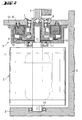
- Fig. 1 shows a schematically marked in its entirety Electric hand tool 1 an electric motor 2 in a housing 3, the first one Gear stage of a gear driving pinion 4 and one, between this and the Electric motor 2 arranged, safety clutch 5.
- Safety clutch 5 advantageously designed as an electromagnetic clutch with a Magnetic coil 6, with an aborting clutch disk designated as a rotor disk 7 and a driving clutch disk designated as armature disk 8.
- the Hollow cylindrical magnet coil 6 includes a radial outer bearing 9 with the Pinion 4 integrally connected pinion shaft 10, the inside of which on the part of the side opposite the pinion 4 is connected in a rotationally fixed manner to the electric motor 2 Receives rotor shaft 11 and coaxially rotatable in an inner bearing 12, which as Plain bearing designed with a centering ball and with sufficiently long axial Sliding surfaces for tilt-free takeover of those picked up by the pinion 4 Transverse forces is provided.
- an inner bearing 12 as Plain bearing designed with a centering ball and with sufficiently long axial Sliding surfaces for tilt-free takeover of those picked up by the pinion 4 Transverse forces is provided.
- the outer bearing 9 arranged in the axial engagement area are both the rotor shaft 11 and, mediated via the inner bearing 12, the Pinion shaft 10 rotatably mounted in the housing 3, one with respect to the electric motor 2 opposite rotor bearing 13 absorbs the transverse forces.
- the rotor disk 7 or the armature disk 8 is surrounded inside External bearing 9 of the pinion shaft 10 and the rotor shaft 11, whereby a Nesting of this outer bearing 9 of the pinion shaft 10 and the rotor shaft 11, the rotor disk 7 and the magnet coil 6 in a narrowly defined axial area arises.
- the Rotor shaft 11 with the armature disk 8 and that designed as a clutch cover Counter surface 16 is in the magnet coil 6 fastened to the end shield 14 of the housing 3 as well as in the inner bearing 12 of the pinion shaft 10 and the rotor disk 7 attached thereto insertable in the direction of the end shield 14.
Landscapes
- Engineering & Computer Science (AREA)
- Mechanical Engineering (AREA)
- Percussive Tools And Related Accessories (AREA)
- Connection Of Motors, Electrical Generators, Mechanical Devices, And The Like (AREA)
- Drilling And Boring (AREA)
- Portable Power Tools In General (AREA)
Abstract
Description
Claims (8)
- Elektrohandwerkzeug (1) mit einem Elektromotor (2), dessen drehfest verbundene Rotorwelle (11) über ein drehfest mit einer Ritzelwelle (10) verbundenes Ritzel (4) ein Getriebe antreibt, wobei zwischen der Rotorwelle (11) und der Ritzelwelle (10) eine Sicherheitskupplung (5) angeordnet ist, dadurch gekennzeichnet, dass in einer Innenlagerung (12) die Rotorwelle (11) axial in die, koaxial drehbar auf dieser gelagerten, Ritzelwelle (10) eingreift.
- Elektrohandwerkzeug nach Anspruch 1, dadurch gekennzeichnet, dass eine radiale Aussenlagerung (9) im axialen Eingriffsbereich der Innenlagerung (12) angeordnet ist.
- Elektrohandwerkzeug nach einem der vorhergehenden Ansprüche, dadurch gekennzeichnet, dass die Innenlagerung (12) als Gleitlager mit hinreichend langen axialen Gleitflächen ausgebildet ist.
- Elektrohandwerkzeug nach einem der vorhergehenden Ansprüche, dadurch gekennzeichnet, dass eine Läuferscheibe (7) auf der Ritzelwelle (10) und eine Ankerscheibe (8) auf der Rotorwelle (11) jeweils drehfest befestigt ist.
- Elektrohandwerkzeug nach Anspruch 4, dadurch gekennzeichnet, dass die der Läuferscheibe (7) abgewandte Stirnfläche der Ankerscheibe (8) im radial Äusseren einen Reibbelag (15) aufweist.
- Elektrohandwerkzeug nach einem der vorhergehenden Ansprüche, dadurch gekennzeichnet, dass die Sicherheitskupplung (5) als elektromagnetische Kupplung ausgeführt ist.
- Elektrohandwerkzeug nach Anspruch 6, dadurch gekennzeichnet, dass eine hohlzylinderförmige Magnetspule (6) im Inneren die Aussenlagerung (9) umfasst.
- Elektrohandwerkzeug nach Anspruch 6 oder Anspruch 7, dadurch gekennzeichnet, dass die Magnetspule (6) an einem Lagerschild (14) für die Aussenlagerung (9) befestigt ist.
Applications Claiming Priority (2)
| Application Number | Priority Date | Filing Date | Title |
|---|---|---|---|
| DE10057139 | 2000-11-17 | ||
| DE10057139A DE10057139A1 (de) | 2000-11-17 | 2000-11-17 | Elektrohandwerkzeug mit Sicherheitskupplung |
Publications (2)
| Publication Number | Publication Date |
|---|---|
| EP1207018A1 true EP1207018A1 (de) | 2002-05-22 |
| EP1207018B1 EP1207018B1 (de) | 2007-05-30 |
Family
ID=7663709
Family Applications (1)
| Application Number | Title | Priority Date | Filing Date |
|---|---|---|---|
| EP01811069A Expired - Lifetime EP1207018B1 (de) | 2000-11-17 | 2001-11-06 | Elektrohandwerkzeug mit Sicherheitskupplung |
Country Status (5)
| Country | Link |
|---|---|
| US (1) | US6705410B2 (de) |
| EP (1) | EP1207018B1 (de) |
| JP (1) | JP4063527B2 (de) |
| CN (1) | CN1357435A (de) |
| DE (2) | DE10057139A1 (de) |
Families Citing this family (26)
| Publication number | Priority date | Publication date | Assignee | Title |
|---|---|---|---|---|
| US6827189B2 (en) * | 2000-07-20 | 2004-12-07 | Zf Friedrichshafen Ag | Electromagnetically actuated, single-surface friction coupling, without a rotor slip ring |
| JP2002254336A (ja) * | 2001-03-02 | 2002-09-10 | Hitachi Koki Co Ltd | 電動工具 |
| US20060135267A1 (en) * | 2002-12-12 | 2006-06-22 | Bosk Brian K | Wedge clutch assembly |
| US6848998B2 (en) | 2002-12-12 | 2005-02-01 | Brian K. Bosk | Wedge clutch assembly |
| US8439763B2 (en) * | 2002-12-12 | 2013-05-14 | Brian K. Bosk | Wedge clutch assembly |
| JP2004227879A (ja) | 2003-01-22 | 2004-08-12 | Hitachi Ltd | パターン検査方法及びパターン検査装置 |
| USD520838S1 (en) * | 2004-11-30 | 2006-05-16 | Hitachi Koki Co., Ltd. | Portable electric hammer drill |
| USD520837S1 (en) * | 2004-11-30 | 2006-05-16 | Hitachi Koki Co., Ltd. | Portable electric hammer |
| GB2427006A (en) * | 2005-06-10 | 2006-12-13 | Black & Decker Inc | Overload clutch with two predetermined torque levels |
| DE102008050703B3 (de) * | 2008-10-07 | 2009-12-31 | Wacker Neuson Se | Arbeitsgerät mit Überholkupplung |
| JP5436135B2 (ja) * | 2008-12-19 | 2014-03-05 | 株式会社マキタ | 作業工具 |
| JP5496605B2 (ja) * | 2009-11-02 | 2014-05-21 | 株式会社マキタ | 打撃工具 |
| JP5395620B2 (ja) * | 2009-11-02 | 2014-01-22 | 株式会社マキタ | 打撃工具 |
| JP5534783B2 (ja) * | 2009-11-10 | 2014-07-02 | 株式会社マキタ | 電動工具 |
| FR2981331B1 (fr) * | 2011-10-14 | 2013-11-15 | Messier Bugatti Dowty | Dispositif de connexion d'un motoreducteur a une roue d'aeronef, pour permettre son entrainement selectif par le motoreducteur. |
| CN208289826U (zh) * | 2015-02-06 | 2018-12-28 | 米沃奇电动工具公司 | 以气弹簧为动力的紧固件驱动器 |
| EP3112087A1 (de) * | 2015-06-30 | 2017-01-04 | HILTI Aktiengesellschaft | Handwerkzeugmaschine mit sicherheitskupplung |
| US11529725B2 (en) | 2017-10-20 | 2022-12-20 | Milwaukee Electric Tool Corporation | Power tool including electromagnetic clutch |
| JP7144927B2 (ja) | 2017-10-23 | 2022-09-30 | 株式会社マキタ | 回転工具 |
| WO2019084280A1 (en) | 2017-10-26 | 2019-05-02 | Milwaukee Electric Tool Corporation | RECLINING CONTROL METHODS FOR ELECTRIC TOOLS |
| US11641102B2 (en) | 2020-03-10 | 2023-05-02 | Smart Wires Inc. | Modular FACTS devices with external fault current protection within the same impedance injection module |
| EP4008477A1 (de) * | 2020-12-04 | 2022-06-08 | Hilti Aktiengesellschaft | Werkzeugmaschine mit einer luftkühlung und verfahren zur kühlung von komponenten einer werkzeugmaschine |
| EP4686076A2 (de) * | 2021-04-16 | 2026-01-28 | Black & Decker, Inc. | Elektrostatische kupplung für ein kraftwerkzeug |
| US11819209B2 (en) * | 2021-08-03 | 2023-11-21 | Covidien Lp | Hand-held surgical instruments |
| CN113863689B (zh) * | 2021-09-02 | 2023-08-08 | 上海建工四建集团有限公司 | 利用自动化手持工具对预制墙板进行调垂的施工方法 |
| US12496682B2 (en) | 2022-08-15 | 2025-12-16 | Techtronic Cordless Gp | Die grinder with an offset gear transmission |
Citations (4)
| Publication number | Priority date | Publication date | Assignee | Title |
|---|---|---|---|---|
| FR1239679A (fr) * | 1958-11-05 | 1960-08-26 | Anstalt Fuer Montage Technik | Appareil perforateur à percussion |
| US5346023A (en) * | 1993-02-11 | 1994-09-13 | Hitachi Koki Company Limited | Slipping torque changing apparatus for impact tool |
| US5711380A (en) * | 1996-08-01 | 1998-01-27 | Chen; Yueh | Rotate percussion hammer/drill shift device |
| US5996707A (en) * | 1995-11-02 | 1999-12-07 | Robert Bosch Gmbh | Hand power tool |
Family Cites Families (8)
| Publication number | Priority date | Publication date | Assignee | Title |
|---|---|---|---|---|
| US4346767A (en) * | 1980-06-11 | 1982-08-31 | Kango Electric Hammers Limited | Rotary impact drill |
| JP3071523B2 (ja) * | 1991-10-08 | 2000-07-31 | 株式会社マキタ | スクリュードライバーにおける回り止め装置 |
| JP2558753Y2 (ja) * | 1991-10-31 | 1998-01-14 | 株式会社マキタ | 回転電動工具の動力伝達機構 |
| DE19717712A1 (de) * | 1997-04-18 | 1998-10-22 | Black & Decker Inc | Bohrhammer |
| JP3628486B2 (ja) * | 1997-06-30 | 2005-03-09 | 株式会社マキタ | ねじ締め機のクラッチ |
| DE19845018C1 (de) * | 1998-09-30 | 1999-12-16 | Fein C & E | Kraftgetriebener Schrauber |
| US6244358B1 (en) * | 2000-01-13 | 2001-06-12 | Snap-On Technologies, Inc. | Trigger and clutch arrangement for power tools |
| DE10029728A1 (de) * | 2000-06-16 | 2001-12-20 | Hilti Ag | Handwerkzeuggerät |
-
2000
- 2000-11-17 DE DE10057139A patent/DE10057139A1/de not_active Withdrawn
-
2001
- 2001-11-06 EP EP01811069A patent/EP1207018B1/de not_active Expired - Lifetime
- 2001-11-06 DE DE50112553T patent/DE50112553D1/de not_active Expired - Lifetime
- 2001-11-09 CN CN01137863A patent/CN1357435A/zh active Pending
- 2001-11-19 JP JP2001352776A patent/JP4063527B2/ja not_active Expired - Fee Related
-
2002
- 2002-01-23 US US10/053,293 patent/US6705410B2/en not_active Expired - Lifetime
Patent Citations (4)
| Publication number | Priority date | Publication date | Assignee | Title |
|---|---|---|---|---|
| FR1239679A (fr) * | 1958-11-05 | 1960-08-26 | Anstalt Fuer Montage Technik | Appareil perforateur à percussion |
| US5346023A (en) * | 1993-02-11 | 1994-09-13 | Hitachi Koki Company Limited | Slipping torque changing apparatus for impact tool |
| US5996707A (en) * | 1995-11-02 | 1999-12-07 | Robert Bosch Gmbh | Hand power tool |
| US5711380A (en) * | 1996-08-01 | 1998-01-27 | Chen; Yueh | Rotate percussion hammer/drill shift device |
Also Published As
| Publication number | Publication date |
|---|---|
| DE50112553D1 (de) | 2007-07-12 |
| JP4063527B2 (ja) | 2008-03-19 |
| US6705410B2 (en) | 2004-03-16 |
| JP2002200579A (ja) | 2002-07-16 |
| DE10057139A1 (de) | 2002-05-23 |
| US20020062967A1 (en) | 2002-05-30 |
| CN1357435A (zh) | 2002-07-10 |
| EP1207018B1 (de) | 2007-05-30 |
Similar Documents
| Publication | Publication Date | Title |
|---|---|---|
| EP1207018B1 (de) | Elektrohandwerkzeug mit Sicherheitskupplung | |
| EP1219392A2 (de) | Elektrohandwerkzeug mit Sicherheitskupplung | |
| DE3802740A1 (de) | Motorisch betriebenes handgeraet | |
| DE69202229T2 (de) | Schalteinrichtung in einer Einwegkupplung des Reibungstyps. | |
| DE112016003913T5 (de) | Angetriebenes Werkzeug | |
| EP1488121A1 (de) | Vorrichtung zur kopplung einer gehauseanordnung einer kopplungseinrichtung mit einer rotoranordnung einer elektromaschine | |
| DE102007019667B4 (de) | Lagervorrichtung | |
| DE3330528C2 (de) | ||
| CH665065A5 (de) | Mit reibungsbremse ausgeruesteter elektrischer motor. | |
| WO2005073584A1 (de) | Lamellenkupplung mit konischen lamellen | |
| DE60205878T2 (de) | Brems-kupplung anordnung | |
| DE2128418A1 (de) | Waschmaschinenantrieb | |
| EP1301726A1 (de) | Elektromagnetisch betätigbare, schleifringlose einflächen-reibungskupplung | |
| DE3446349C2 (de) | ||
| DE69106070T2 (de) | Kupplungseinheit. | |
| DE202007006169U1 (de) | Antriebsanordnung für Seilbahnen sowie Brems- und Kupplungseinheit hierfür | |
| DE102009029877A1 (de) | Torquemotor mit Brems- und/oder Halteeinrichtung | |
| DE19905390C1 (de) | Aufzugsantrieb mit elektrischem Antriebsmotor | |
| DE10221625A1 (de) | Vorrichtung zur Kopplung einer Gehäuseanordnung einer Kopplungseinrichtung mit einer Rotoranordnung einer Elektromaschine | |
| EP1513649B1 (de) | Zahnstangenantrieb mit bremseinheit | |
| DE3048532A1 (de) | Reibungsdaempfer fuer die abstuetzung einer bewegten vorrichtung | |
| DE3742163A1 (de) | Kupplung fuer handgefuehrte elektrowerkzeuge | |
| DE102017209013A1 (de) | Handwerkzeugmaschine mit einer Sicherungseinheit | |
| DE3205980C2 (de) | Elektromagnetische Haltebremse | |
| DE529829C (de) | Als Motor oder als Generator arbeitende elektrische Maschine, deren Laeufer mit der Welle durch eine Anlasskupplung verbunden ist |
Legal Events
| Date | Code | Title | Description |
|---|---|---|---|
| PUAI | Public reference made under article 153(3) epc to a published international application that has entered the european phase |
Free format text: ORIGINAL CODE: 0009012 |
|
| AX | Request for extension of the european patent |
Free format text: AL;LT;LV;MK;RO;SI |
|
| 17P | Request for examination filed |
Effective date: 20021122 |
|
| AKX | Designation fees paid |
Designated state(s): CH DE FR GB LI SE |
|
| GRAP | Despatch of communication of intention to grant a patent |
Free format text: ORIGINAL CODE: EPIDOSNIGR1 |
|
| GRAS | Grant fee paid |
Free format text: ORIGINAL CODE: EPIDOSNIGR3 |
|
| GRAA | (expected) grant |
Free format text: ORIGINAL CODE: 0009210 |
|
| AK | Designated contracting states |
Kind code of ref document: B1 Designated state(s): CH DE FR GB LI SE |
|
| REG | Reference to a national code |
Ref country code: GB Ref legal event code: FG4D Free format text: NOT ENGLISH |
|
| REG | Reference to a national code |
Ref country code: CH Ref legal event code: EP |
|
| REF | Corresponds to: |
Ref document number: 50112553 Country of ref document: DE Date of ref document: 20070712 Kind code of ref document: P |
|
| GBT | Gb: translation of ep patent filed (gb section 77(6)(a)/1977) |
Effective date: 20070704 |
|
| REG | Reference to a national code |
Ref country code: SE Ref legal event code: TRGR |
|
| ET | Fr: translation filed | ||
| PLBE | No opposition filed within time limit |
Free format text: ORIGINAL CODE: 0009261 |
|
| STAA | Information on the status of an ep patent application or granted ep patent |
Free format text: STATUS: NO OPPOSITION FILED WITHIN TIME LIMIT |
|
| 26N | No opposition filed |
Effective date: 20080303 |
|
| REG | Reference to a national code |
Ref country code: FR Ref legal event code: PLFP Year of fee payment: 15 |
|
| REG | Reference to a national code |
Ref country code: FR Ref legal event code: PLFP Year of fee payment: 16 |
|
| REG | Reference to a national code |
Ref country code: FR Ref legal event code: PLFP Year of fee payment: 17 |
|
| PGFP | Annual fee paid to national office [announced via postgrant information from national office to epo] |
Ref country code: DE Payment date: 20181120 Year of fee payment: 18 Ref country code: SE Payment date: 20181120 Year of fee payment: 18 |
|
| PGFP | Annual fee paid to national office [announced via postgrant information from national office to epo] |
Ref country code: GB Payment date: 20181120 Year of fee payment: 18 Ref country code: FR Payment date: 20181121 Year of fee payment: 18 Ref country code: CH Payment date: 20181120 Year of fee payment: 18 |
|
| REG | Reference to a national code |
Ref country code: DE Ref legal event code: R119 Ref document number: 50112553 Country of ref document: DE |
|
| REG | Reference to a national code |
Ref country code: SE Ref legal event code: EUG Ref country code: CH Ref legal event code: PL |
|
| PG25 | Lapsed in a contracting state [announced via postgrant information from national office to epo] |
Ref country code: CH Free format text: LAPSE BECAUSE OF NON-PAYMENT OF DUE FEES Effective date: 20191130 Ref country code: LI Free format text: LAPSE BECAUSE OF NON-PAYMENT OF DUE FEES Effective date: 20191130 |
|
| PG25 | Lapsed in a contracting state [announced via postgrant information from national office to epo] |
Ref country code: SE Free format text: LAPSE BECAUSE OF NON-PAYMENT OF DUE FEES Effective date: 20191107 |
|
| GBPC | Gb: european patent ceased through non-payment of renewal fee |
Effective date: 20191106 |
|
| PG25 | Lapsed in a contracting state [announced via postgrant information from national office to epo] |
Ref country code: DE Free format text: LAPSE BECAUSE OF NON-PAYMENT OF DUE FEES Effective date: 20200603 Ref country code: FR Free format text: LAPSE BECAUSE OF NON-PAYMENT OF DUE FEES Effective date: 20191130 Ref country code: GB Free format text: LAPSE BECAUSE OF NON-PAYMENT OF DUE FEES Effective date: 20191106 |