EP1213227A1 - Beverage container with means to keep the contents warm or cold - Google Patents
Beverage container with means to keep the contents warm or cold Download PDFInfo
- Publication number
- EP1213227A1 EP1213227A1 EP02003700A EP02003700A EP1213227A1 EP 1213227 A1 EP1213227 A1 EP 1213227A1 EP 02003700 A EP02003700 A EP 02003700A EP 02003700 A EP02003700 A EP 02003700A EP 1213227 A1 EP1213227 A1 EP 1213227A1
- Authority
- EP
- European Patent Office
- Prior art keywords
- container
- insert
- external cavity
- peripheral wall
- contents
- Prior art date
- Legal status (The legal status is an assumption and is not a legal conclusion. Google has not performed a legal analysis and makes no representation as to the accuracy of the status listed.)
- Withdrawn
Links
Images


Classifications
-
- B—PERFORMING OPERATIONS; TRANSPORTING
- B65—CONVEYING; PACKING; STORING; HANDLING THIN OR FILAMENTARY MATERIAL
- B65D—CONTAINERS FOR STORAGE OR TRANSPORT OF ARTICLES OR MATERIALS, e.g. BAGS, BARRELS, BOTTLES, BOXES, CANS, CARTONS, CRATES, DRUMS, JARS, TANKS, HOPPERS, FORWARDING CONTAINERS; ACCESSORIES, CLOSURES, OR FITTINGS THEREFOR; PACKAGING ELEMENTS; PACKAGES
- B65D25/00—Details of other kinds or types of rigid or semi-rigid containers
- B65D25/02—Internal fittings
-
- B—PERFORMING OPERATIONS; TRANSPORTING
- B65—CONVEYING; PACKING; STORING; HANDLING THIN OR FILAMENTARY MATERIAL
- B65D—CONTAINERS FOR STORAGE OR TRANSPORT OF ARTICLES OR MATERIALS, e.g. BAGS, BARRELS, BOTTLES, BOXES, CANS, CARTONS, CRATES, DRUMS, JARS, TANKS, HOPPERS, FORWARDING CONTAINERS; ACCESSORIES, CLOSURES, OR FITTINGS THEREFOR; PACKAGING ELEMENTS; PACKAGES
- B65D81/00—Containers, packaging elements, or packages, for contents presenting particular transport or storage problems, or adapted to be used for non-packaging purposes after removal of contents
- B65D81/18—Containers, packaging elements, or packages, for contents presenting particular transport or storage problems, or adapted to be used for non-packaging purposes after removal of contents providing specific environment for contents, e.g. temperature above or below ambient
-
- B—PERFORMING OPERATIONS; TRANSPORTING
- B65—CONVEYING; PACKING; STORING; HANDLING THIN OR FILAMENTARY MATERIAL
- B65D—CONTAINERS FOR STORAGE OR TRANSPORT OF ARTICLES OR MATERIALS, e.g. BAGS, BARRELS, BOTTLES, BOXES, CANS, CARTONS, CRATES, DRUMS, JARS, TANKS, HOPPERS, FORWARDING CONTAINERS; ACCESSORIES, CLOSURES, OR FITTINGS THEREFOR; PACKAGING ELEMENTS; PACKAGES
- B65D81/00—Containers, packaging elements, or packages, for contents presenting particular transport or storage problems, or adapted to be used for non-packaging purposes after removal of contents
- B65D81/34—Containers, packaging elements, or packages, for contents presenting particular transport or storage problems, or adapted to be used for non-packaging purposes after removal of contents for packaging foodstuffs or other articles intended to be cooked or heated within the package
- B65D81/3484—Packages having self-contained heating means, e.g. heating generated by the reaction of two chemicals
-
- F—MECHANICAL ENGINEERING; LIGHTING; HEATING; WEAPONS; BLASTING
- F25—REFRIGERATION OR COOLING; COMBINED HEATING AND REFRIGERATION SYSTEMS; HEAT PUMP SYSTEMS; MANUFACTURE OR STORAGE OF ICE; LIQUEFACTION SOLIDIFICATION OF GASES
- F25D—REFRIGERATORS; COLD ROOMS; ICE-BOXES; COOLING OR FREEZING APPARATUS NOT OTHERWISE PROVIDED FOR
- F25D31/00—Other cooling or freezing apparatus
- F25D31/006—Other cooling or freezing apparatus specially adapted for cooling receptacles, e.g. tanks
- F25D31/007—Bottles or cans
-
- F—MECHANICAL ENGINEERING; LIGHTING; HEATING; WEAPONS; BLASTING
- F25—REFRIGERATION OR COOLING; COMBINED HEATING AND REFRIGERATION SYSTEMS; HEAT PUMP SYSTEMS; MANUFACTURE OR STORAGE OF ICE; LIQUEFACTION SOLIDIFICATION OF GASES
- F25D—REFRIGERATORS; COLD ROOMS; ICE-BOXES; COOLING OR FREEZING APPARATUS NOT OTHERWISE PROVIDED FOR
- F25D2331/00—Details or arrangements of other cooling or freezing apparatus not provided for in other groups of this subclass
- F25D2331/80—Type of cooled receptacles
- F25D2331/805—Cans
-
- F—MECHANICAL ENGINEERING; LIGHTING; HEATING; WEAPONS; BLASTING
- F25—REFRIGERATION OR COOLING; COMBINED HEATING AND REFRIGERATION SYSTEMS; HEAT PUMP SYSTEMS; MANUFACTURE OR STORAGE OF ICE; LIQUEFACTION SOLIDIFICATION OF GASES
- F25D—REFRIGERATORS; COLD ROOMS; ICE-BOXES; COOLING OR FREEZING APPARATUS NOT OTHERWISE PROVIDED FOR
- F25D3/00—Devices using other cold materials; Devices using cold-storage bodies
- F25D3/02—Devices using other cold materials; Devices using cold-storage bodies using ice, e.g. ice-boxes
- F25D3/06—Movable containers
- F25D3/08—Movable containers portable, i.e. adapted to be carried personally
-
- F—MECHANICAL ENGINEERING; LIGHTING; HEATING; WEAPONS; BLASTING
- F25—REFRIGERATION OR COOLING; COMBINED HEATING AND REFRIGERATION SYSTEMS; HEAT PUMP SYSTEMS; MANUFACTURE OR STORAGE OF ICE; LIQUEFACTION SOLIDIFICATION OF GASES
- F25D—REFRIGERATORS; COLD ROOMS; ICE-BOXES; COOLING OR FREEZING APPARATUS NOT OTHERWISE PROVIDED FOR
- F25D3/00—Devices using other cold materials; Devices using cold-storage bodies
- F25D3/10—Devices using other cold materials; Devices using cold-storage bodies using liquefied gases, e.g. liquid air
- F25D3/107—Devices using other cold materials; Devices using cold-storage bodies using liquefied gases, e.g. liquid air portable, i.e. adapted to be carried personally
Definitions
- the present invention relates to containers.
- US-A-4,656,838 describes a container for a beverage having a tubular peripheral wall defining two spaced open ends, one open end being closed by a top member, and the other open end being closed by a base member, said peripheral wall and the top and base members defining an internal cavity for containing a beverage, wherein said base member is indented to define an external cavity which extends within said peripheral wall substantially along the longitudinal axis of said container, and wherein said external cavity extends within the internal cavity, but is separated therefrom by said base member.
- the container in this US specification is operable to cool or refrigerate the beverage in the can.
- a container as defined above is characterised in that said external cavity retains insert means arranged to keep the contents within the internal cavity warm or cold.
- the external cavity may be provided in any conventional container without affecting the external configuration or size of the container, although it does reduce the capacity thereof. This means that a container of an embodiment of the invention can be filled on existing filling lines without difficulty. Furthermore, because of its longitudinal extent, the external cavity provides a large surface area in contact with the contents of the container for heat transfer.
- the insert may be selected from a plurality of different inserts such that the container may be arranged to be cool retaining, or heat retaining, at the choice of the manufacturer, retailer or user.
- the base member is formed from sheet material, preferably of a conductive material.
- the sheet material of the base member is generally metal, preferably aluminium.
- the sheet material of the base member is shaped to form a peripheral defining wall of said external cavity. It will be appreciated that one surface of said peripheral defining wall will be within the external cavity, and that the opposed surface of the peripheral defining wall will be within the internal cavity.
- At least said opposed surface of said peripheral defining wall has means to extend its surface area.
- Such surface area extending means may be, for example, vanes or other configurations provided on said opposed surface.
- the use of an extended surface area aids in heat transfer.
- the container, and its external cavity may be of any appropriate shape, configuration and size.
- the tubular peripheral wall is substantially cylindrical defining, for example, a generally cylindrical container or can.
- the external cavity is substantially cylindrical with a domed, closed end.
- the container may be made by any appropriate means.
- the container may be manufactured in two parts.
- the container will be manufactured in three parts, namely, the shaped base member, the peripheral wall, and the top member.
- the container may be of any appropriate material, for example, of plastics material. However, as it is generally required that the peripheral defining wall of the external cavity be of metal or other conductive material, it is presently preferred that the rest of the container be made of the same material.
- the metal of the container may be, for example, aluminium.
- the outer surface of the peripheral wall may be insulated in any required manner.
- an outer wrapper of a plastics material may be provided on the exterior of the peripheral wall.
- the peripheral wall, at least, of the container may be made of a plastics material sufficiently thick to provide for heat insulation.
- the insert means may be an elongate insert provided with a peripheral wall.
- the insert means does not have a peripheral wall and insert material is directly retained within the external cavity.
- One or more insert means may be provided for retention within the external cavity of the container.
- the insert means is an elongate insert which is arranged to be retained by a push fit within the external cavity. Not only does this simplify the retention of the insert, but is also ensures good heat conducting contact between the insert and between the peripheral defining wall of the external cavity.
- each insert is shaped to have an external configuration which is substantially the same as the internal configuration of the external cavity.
- each insert may be substantially cylindrical with a domed top and a planar base.
- the insert may be arranged to keep the contents of a container cool.
- the insert may comprise a freezable material. This material is preferably one which melts at less than 5°C, for example, water, heavy water or a freezable gel. It will be appreciated that if a frozen insert is inserted into the external cavity of a cooled container, the insert will act to absorb heat from the contents of the container, such heat tending to melt the frozen material of the insert. Such a frozen insert may be effective in keeping the container contents chilled for up to 8 hours.
- a bottom cap is provided to extend across the base of the external cavity when the insert means is retained therein. Such a cap may act to deny accidental access to the insert means.
- the present invention relates to a container, such as a can, for beverages which is provided with means to keep the contents warm or cold.
- a container such as a can
- beverages which is provided with means to keep the contents warm or cold.
- beverages such as beer, soft drinks and iced tea cool.
- drinks such as tea, coffee, hot chocolate and soup warm.
- a container of the present invention can achieve these functions by choice of an appropriate insert.
- Embodiments of the beverage containers described herein may also be used to have a self-cooling or self-heating function. However, such embodiments are not within the scope of this application.
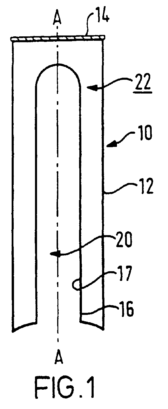
- Figure 1 shows a cross section through a beverage container 10.
- This container 10 has a substantially cylindrical peripheral wall 12 which is closed at one open end by a top member 14.
- a conventional container as 10 would also have a generally planar base closing the other open end of the peripheral wall 12.
- the container 10 of the invention has a base member 16 formed from sheet material to define an elongate, external cavity 20 which extends within the peripheral wall 12 substantially along the longitudinal axis A-A of the container 10. It will be appreciated that the peripheral wall 12 and the top and base members 14 and 16 of the container together define an internal cavity 22 in which the beverage is received. It will be seen that the external cavity 20 extends within this internal cavity 22, but is separated therefrom by the peripheral defining wall 17 of the external cavity 20 which is formed by the base member 16.
- the container 10 illustrated in Figure 1 is configured to have the same external dimensions and shape as a conventional half litre beer can. However, the presence of the external cavity 20 reduces its capacity.
- the arrangement shown in Figure 1 reduces the capacity of a half litre can to 33 litre.
- Figure 2 illustrates an alternative configuration which reduces the capacity of a half litre can to .44 litre.
- each of the cans of Figures 1 and 2 has the same external dimensions as conventional cans, and therefore each can be used and filled on existing filling lines.
- the external cavity 20 of the can 10 is to be utilised to enclose an insert to effect heating or cooling of the can, or to keep the contents thereof warm or cool.
- the external cavity 20 extends over a major part of the length of the longitudinal axis A-A of the can 10. This provides the peripheral defining wall 17 of the external cavity 20 with a large surface area within the can 10 to enhance heat conduction. If necessary, vanes or other surface area extending devices may be carried on the surface of the peripheral defining wall 17 which is within the internal cavity 22. Such surface extending means (not shown) enhance heat conduction between the internal and external cavities 20, 22 without interfering with the filling of the container on a conventional filling line.
- a can 10, as show in Figure 1 may be used with a selected insert to obtain the effect required.
- the insert may be mounted in the can after it has been filled and sealed. This means that any treatments required on the can and its contents may be made without any adverse effects on the insert.
- a filled can 10, as shown in Figure 1 may be subjected to a pasteurisation process if required.
- Figures 2 to 4 show an embodiment of a can 10 to be used to keep cold drinks cold.
- the can 10 shown in Figure 2 is substantially identical to that of Figure 1 except that the external cavity 20 is somewhat narrower.
- the can 10 of Figure 2 has been covered with an insulating material sleeve 24, and a top cap 26 and a bottom cap 28 of an insulating material are provided.
- Figure 3 shows an insert 30 which can be inserted into the external cavity 20 of the can 10 as shown in Figure 2.
- the insert 30 is configured to be a push fit within the cavity 20 such that specific retention means will not generally be required.
- the external periphery of the insert 30 is substantially the same size and shape as the internal periphery of the external cavity 20 to ensure good heat conduction.
- the bottom insulating cap 28 co-operates with the can 10 and the insert 30 and may have a function of aiding the retention of the insert 30.
- the bottom insulating cap 28 is provided simply to keep the contents of the can cold and/or to act as a tamper proof seal.
- the insert 30 of Figure 3 is a metal cylinder, for example, filled with a material 31 which melts at a temperature of less than 5°C.
- the material 31 within the insert 30 may be water, heavy water, or a gel with a low melting temperature.
- the can as shown in Figures 2 to 4 may be assembled by the user or by a retailer.
- the can 10 with its contents, but without its insert 30, is stored in a refrigerator, and the insert 30 is kept in a freezer until the material 31 therein is frozen solid.
- the insert 30 is removed from the refrigerator and the frozen insert 30 is inserted in its cavity 20.
- the insulating cap 28 is put in place.
- the contents of the can will keep cool for up to 8 hours. This means that the can 10 can be transported, or left without refrigeration, for this time and a chilled drink will still be available from it.
- the defining wall 17 be of metal and that the wall of the insert 30 similarly be of metal. It may also be desirable to interpose a conductive gel between the insert 30 and the defining wall 17.
- the insert 30 be contained by a peripheral wall although it is preferable. It would, for example, be possible to pack ice cubes with cold water into the external cavity 20. Of course, in this case a water tight seal would be required for the base of the external cavity 20.
- Any insert material which has a low melting temperature and can absorb heat over an extended period may be used in place of the frozen water, frozen heavy water, or frozen gel to provide an insert 30 to keep the contents cold.
- a warmed can 10 it is equally possible to keep the contents of a warmed can 10 warm by use of a heated insert.
- an insert, as 30, filled with a heat retaining gel may be heated and then inserted into the external cavity 20 to keep the heated contents of the can warm.
- Figure 5 shows an insert 40 arranged to cool or chill the contents of a can 10.
- the insert 40 is a cylinder having a gas chamber 48 containing carbon dioxide under pressure.
- the gas is pressurised to the extent that it is liquid.
- a valve (not shown) is provided to control an opening 42 of the gas chamber 48. When the valve is opened, the gas vents, and as it does so it evaporates and absorbs heat.
- carbon dioxide may be vented directly to atmosphere the insert 40 shown in Figure 5 includes an expansion chamber 44 in which the vented gas may expand. In this manner, the flow rate of the gas as it exits through a port defined in a base structure 46 is reduced for safety.
- the relative sizes of the gas chamber 48 and of the expansion chamber 44 may be chosen as required.
- the gas within the gas chamber 48 may be any gas which would be subjected to a change of phase at appropriate temperatures. Some gases may have to be flowed through a catalyst or chemicals before they are vented to atmosphere and such catalysts or chemicals may be provided within the chamber 44.
- the self-cooling can incorporating an insert as 40 is preferably manufactured with the insert in place.
- the base structure 46 of the insert, which supports the vent valve, is received within an appropriate recess in the base member 16.
- a bottom cap, as 28, is preferably retained on the can to hide the base structure 46 from view and prevent accidental actuation. Preferably, destruction of the bottom cap 28 is required to give access to the base structure 46.
- the bottom cap 28 therefore provides an indication of tampering.
- an insert capable of absorbing heat is inserted in the external cavity of the can.
- Any appropriate insert may be used.
- an electrically powered insert such as one utilizing the Peltier effect, may be provided.
- An electrically powered insert may include appropriate batteries or the insert may be connected to mains or external battery power.
- Figure 6 shows an insert 50 for heating the contents of a can 10.
- the illustrated insert 50 uses water and lime to provide an exothermic chemical reaction but any other constituents generating heat may be utilised.
- the insert 50 shown in Figure 6 comprises a generally cylindrical metal cylinder which has a plurality of spaced, longitudinally extending channels 52 along its outer surface. Thus, when the insert 50 is within the external cavity 20, the channels 52 extend between the insert 50 and the wall 17 of the cavity 20. Internally the length of the cylinder 50 is divided by a membrane 54 into two chambers 56, 58. The first of these chambers 56 contains lime, and the second of these chambers 58 contains water. Within the water chamber 58 there is also a membrane piercer 60 which is actuatable by a button 62 provided at the bottom of the insert 50. A tamper evident seal 64 may also be provided.
- the insert 50 is received within the external cavity 20 of a container 10 so that the button 62 is at the base of the can.
- the base wall 16 of the can is shaped to provide a domed base and it is within this dome that the button 62 can be accommodated.
- the can 10 In its normal state, the can 10 will have a base cap, as 28, which protects the button 62.
- the can When it is required to heat the contents of the can, the can is stood on its top so that its base is accessible. Any base cap 28 is removed so that the button 62 is accessible. Depression of the button 62 causes the membrane 54 to be pierced by the membrane piercer 60 and hence water from the chamber 58 flows over the lime in chamber 56 causing the exothermic reaction.
- the steam which is generated exits through a membrane covered vent 66 provided on the top dome of the insert 50 and the steam is discharged from the container by way of the channels 52.
- the user will retain the can on its top until the exit of the steam has been completed.
- the contents of the can will have been heated to a satisfactory temperature. For example, it can take less than two minutes to heat the contents of the can to 70°C. At this juncture, the can is turned the correct way up, and the contents of the can can be dispensed in the normal way.
- an insert capable of generating heat is inserted into the external cavity of the can.
- Any appropriate insert may be used.
- any appropriate chemical reaction may be utilised to provide the heating.
- the heating may be electrically powered, and the insert may include batteries or be connected to mains or external battery power.
Landscapes
- Engineering & Computer Science (AREA)
- Mechanical Engineering (AREA)
- Chemical & Material Sciences (AREA)
- Combustion & Propulsion (AREA)
- Physics & Mathematics (AREA)
- Thermal Sciences (AREA)
- General Engineering & Computer Science (AREA)
- Life Sciences & Earth Sciences (AREA)
- Food Science & Technology (AREA)
- Packages (AREA)
Abstract
Description
- The present invention relates to containers.
- There have been many proposals for self-heating or self-cooling containers. Generally, however, these proposals have required entirely new configurations of containers to be provided which cannot be used on existing filling lines. EP-A-0297724, for example, cannot be filled conventionally. Such containers therefore require a heavy investment by beverage manufacturers. Other proposals require the heating or cooling means to be incorporated within the container before it is filled. This generally prevents pasteurising, sterilising, or other treatments being made on the contents of the container because of the risk of damaging or adversely affecting the heating or cooling means.
- US-A-4,656,838 describes a container for a beverage having a tubular peripheral wall defining two spaced open ends, one open end being closed by a top member, and the other open end being closed by a base member, said peripheral wall and the top and base members defining an internal cavity for containing a beverage, wherein said base member is indented to define an external cavity which extends within said peripheral wall substantially along the longitudinal axis of said container, and wherein said external cavity extends within the internal cavity, but is separated therefrom by said base member.
- The container in this US specification is operable to cool or refrigerate the beverage in the can.
- It is an object of the present invention to seek to reduce the disadvantages of prior proposals.
- According to the present invention a container as defined above is characterised in that said external cavity retains insert means arranged to keep the contents within the internal cavity warm or cold.
- The external cavity may be provided in any conventional container without affecting the external configuration or size of the container, although it does reduce the capacity thereof. This means that a container of an embodiment of the invention can be filled on existing filling lines without difficulty. Furthermore, because of its longitudinal extent, the external cavity provides a large surface area in contact with the contents of the container for heat transfer.
- Preferably, the insert may be selected from a plurality of different inserts such that the container may be arranged to be cool retaining, or heat retaining, at the choice of the manufacturer, retailer or user.
- In a preferred embodiment, the base member is formed from sheet material, preferably of a conductive material. In this respect, for good heat transfer it is important to retain good heat conductivity between the insert in the external cavity and the contents in the internal cavity of the container. Thus, the sheet material of the base member is generally metal, preferably aluminium.
- In an embodiment, the sheet material of the base member is shaped to form a peripheral defining wall of said external cavity. It will be appreciated that one surface of said peripheral defining wall will be within the external cavity, and that the opposed surface of the peripheral defining wall will be within the internal cavity.
- Preferably, at least said opposed surface of said peripheral defining wall has means to extend its surface area.
- Such surface area extending means may be, for example, vanes or other configurations provided on said opposed surface. The use of an extended surface area aids in heat transfer.
- The container, and its external cavity, may be of any appropriate shape, configuration and size. In a preferred embodiment, the tubular peripheral wall is substantially cylindrical defining, for example, a generally cylindrical container or can.
- Preferably, the external cavity is substantially cylindrical with a domed, closed end.
- The container may be made by any appropriate means. For example, the container may be manufactured in two parts. Presently, it is envisaged that the container will be manufactured in three parts, namely, the shaped base member, the peripheral wall, and the top member.
- The container may be of any appropriate material, for example, of plastics material. However, as it is generally required that the peripheral defining wall of the external cavity be of metal or other conductive material, it is presently preferred that the rest of the container be made of the same material. The metal of the container may be, for example, aluminium.
- It may be required to insulate the contents of the container and/or to protect users from the heat or cold of the container. In this respect, the outer surface of the peripheral wall may be insulated in any required manner. For example, an outer wrapper of a plastics material may be provided on the exterior of the peripheral wall.
- In an alternative embodiment the peripheral wall, at least, of the container may be made of a plastics material sufficiently thick to provide for heat insulation.
- The insert means may be an elongate insert provided with a peripheral wall. Alternatively, the insert means does not have a peripheral wall and insert material is directly retained within the external cavity.
- One or more insert means may be provided for retention within the external cavity of the container.
- It is preferred that a range of insert means be provided so that a range of containers with different functions may similarly be provided.
- Generally, it is preferred that the insert means is an elongate insert which is arranged to be retained by a push fit within the external cavity. Not only does this simplify the retention of the insert, but is also ensures good heat conducting contact between the insert and between the peripheral defining wall of the external cavity.
- Preferably, the insert is shaped to have an external configuration which is substantially the same as the internal configuration of the external cavity. For example, each insert may be substantially cylindrical with a domed top and a planar base.
- The insert may be arranged to keep the contents of a container cool. For example, the insert may comprise a freezable material. This material is preferably one which melts at less than 5°C, for example, water, heavy water or a freezable gel. It will be appreciated that if a frozen insert is inserted into the external cavity of a cooled container, the insert will act to absorb heat from the contents of the container, such heat tending to melt the frozen material of the insert. Such a frozen insert may be effective in keeping the container contents chilled for up to 8 hours.
- Preferably, a bottom cap is provided to extend across the base of the external cavity when the insert means is retained therein. Such a cap may act to deny accidental access to the insert means.
- Embodiments of the present invention will hereinafter be described, by way of example, with reference to the accompanying drawings, in which:
- Figure 1 shows a cross section of a first embodiment of a beverage container of the present invention,
- Figure 2 shows a second embodiment of a beverage container of the invention provided with insulation,
- Figure 3 shows an elongate insert for use with the container of Figure 2,
- Figure 4 shows a cross section through the container of Figure 2 with the insert and insulation in place,
- Figure 5 shows one example of an insert for cooling a container, and
- Figure 6 shows one example of an insert for heating a container.
-
- The present invention relates to a container, such as a can, for beverages which is provided with means to keep the contents warm or cold. In this respect, it is generally required to keep beverages such as beer, soft drinks and iced tea cool. It is generally required to keep drinks such as tea, coffee, hot chocolate and soup warm. A container of the present invention can achieve these functions by choice of an appropriate insert.
- Embodiments of the beverage containers described herein may also be used to have a self-cooling or self-heating function. However, such embodiments are not within the scope of this application.
- Figure 1 shows a cross section through a
beverage container 10. Thiscontainer 10 has a substantially cylindricalperipheral wall 12 which is closed at one open end by atop member 14. A conventional container as 10 would also have a generally planar base closing the other open end of theperipheral wall 12. However, and as can be seen in Figure 1, thecontainer 10 of the invention has abase member 16 formed from sheet material to define an elongate,external cavity 20 which extends within theperipheral wall 12 substantially along the longitudinal axis A-A of thecontainer 10. It will be appreciated that theperipheral wall 12 and the top andbase members internal cavity 22 in which the beverage is received. It will be seen that theexternal cavity 20 extends within thisinternal cavity 22, but is separated therefrom by the peripheral definingwall 17 of theexternal cavity 20 which is formed by thebase member 16. - The
container 10 illustrated in Figure 1 is configured to have the same external dimensions and shape as a conventional half litre beer can. However, the presence of theexternal cavity 20 reduces its capacity. The arrangement shown in Figure 1 reduces the capacity of a half litre can to 33 litre. Figure 2 illustrates an alternative configuration which reduces the capacity of a half litre can to .44 litre. However, each of the cans of Figures 1 and 2 has the same external dimensions as conventional cans, and therefore each can be used and filled on existing filling lines. - The
external cavity 20 of thecan 10 is to be utilised to enclose an insert to effect heating or cooling of the can, or to keep the contents thereof warm or cool. To be effective, theexternal cavity 20 extends over a major part of the length of the longitudinal axis A-A of thecan 10. This provides the peripheral definingwall 17 of theexternal cavity 20 with a large surface area within thecan 10 to enhance heat conduction. If necessary, vanes or other surface area extending devices may be carried on the surface of the peripheral definingwall 17 which is within theinternal cavity 22. Such surface extending means (not shown) enhance heat conduction between the internal andexternal cavities - As has been made clear above, a
can 10, as show in Figure 1, may be used with a selected insert to obtain the effect required. The insert may be mounted in the can after it has been filled and sealed. This means that any treatments required on the can and its contents may be made without any adverse effects on the insert. For example, a filledcan 10, as shown in Figure 1, may be subjected to a pasteurisation process if required. - Figures 2 to 4 show an embodiment of a
can 10 to be used to keep cold drinks cold. Thecan 10 shown in Figure 2 is substantially identical to that of Figure 1 except that theexternal cavity 20 is somewhat narrower. In addition, thecan 10 of Figure 2 has been covered with an insulatingmaterial sleeve 24, and atop cap 26 and abottom cap 28 of an insulating material are provided. Figure 3 shows aninsert 30 which can be inserted into theexternal cavity 20 of thecan 10 as shown in Figure 2. Theinsert 30 is configured to be a push fit within thecavity 20 such that specific retention means will not generally be required. Furthermore, the external periphery of theinsert 30 is substantially the same size and shape as the internal periphery of theexternal cavity 20 to ensure good heat conduction. Of course, and as is apparent from Figure 4, thebottom insulating cap 28 co-operates with thecan 10 and theinsert 30 and may have a function of aiding the retention of theinsert 30. - Generally, however, the
bottom insulating cap 28 is provided simply to keep the contents of the can cold and/or to act as a tamper proof seal. - The
insert 30 of Figure 3 is a metal cylinder, for example, filled with a material 31 which melts at a temperature of less than 5°C. Thematerial 31 within theinsert 30 may be water, heavy water, or a gel with a low melting temperature. - The can as shown in Figures 2 to 4 may be assembled by the user or by a retailer. Thus, the
can 10 with its contents, but without itsinsert 30, is stored in a refrigerator, and theinsert 30 is kept in a freezer until the material 31 therein is frozen solid. When it is required to use thecan 10, it is removed from the refrigerator and thefrozen insert 30 is inserted in itscavity 20. The insulatingcap 28 is put in place. In this configuration, with all of the surfaces insulated, and theinsert 30 in position, the contents of the can will keep cool for up to 8 hours. This means that thecan 10 can be transported, or left without refrigeration, for this time and a chilled drink will still be available from it. - It would be possible to use a
frozen insert 30, for example, as shown in Figure 3, to chill the contents of acan 10, if required. - To work efficiently, good heat conduction is required between the
insert 30 and the peripheral defining wall of theexternal cavity 20. Therefore, it is generally preferred that the definingwall 17 be of metal and that the wall of theinsert 30 similarly be of metal. It may also be desirable to interpose a conductive gel between theinsert 30 and the definingwall 17. - It is not essential that the
insert 30 be contained by a peripheral wall although it is preferable. It would, for example, be possible to pack ice cubes with cold water into theexternal cavity 20. Of course, in this case a water tight seal would be required for the base of theexternal cavity 20. - Any insert material which has a low melting temperature and can absorb heat over an extended period may be used in place of the frozen water, frozen heavy water, or frozen gel to provide an
insert 30 to keep the contents cold. - It is equally possible to keep the contents of a warmed can 10 warm by use of a heated insert. For example, an insert, as 30, filled with a heat retaining gel may be heated and then inserted into the
external cavity 20 to keep the heated contents of the can warm. - Figure 5 shows an
insert 40 arranged to cool or chill the contents of acan 10. Theinsert 40 is a cylinder having agas chamber 48 containing carbon dioxide under pressure. The gas is pressurised to the extent that it is liquid. A valve (not shown) is provided to control anopening 42 of thegas chamber 48. When the valve is opened, the gas vents, and as it does so it evaporates and absorbs heat. Although carbon dioxide may be vented directly to atmosphere theinsert 40 shown in Figure 5 includes an expansion chamber 44 in which the vented gas may expand. In this manner, the flow rate of the gas as it exits through a port defined in abase structure 46 is reduced for safety. - The relative sizes of the
gas chamber 48 and of the expansion chamber 44 may be chosen as required. The gas within thegas chamber 48 may be any gas which would be subjected to a change of phase at appropriate temperatures. Some gases may have to be flowed through a catalyst or chemicals before they are vented to atmosphere and such catalysts or chemicals may be provided within the chamber 44. - The self-cooling can incorporating an insert as 40 is preferably manufactured with the insert in place. The
base structure 46 of the insert, which supports the vent valve, is received within an appropriate recess in thebase member 16. A bottom cap, as 28, is preferably retained on the can to hide thebase structure 46 from view and prevent accidental actuation. Preferably, destruction of thebottom cap 28 is required to give access to thebase structure 46. Thebottom cap 28 therefore provides an indication of tampering. - When it is required to dispense cooled contents from the
can 10, it is turned upside down. Thebottom cap 28 is removed, and the vent valve is actuated to vent the gas in thegas chamber 48 to atmosphere. The can is retained in this position for the few minutes necessary for all the gas to vent. Those few minutes enable the heat to be extracted from the can contents by the evaporating gas, whereby the can contents are chilled. The can may then be turned the correct way up and opened at the top to provide access to the contents in the usual manner. - Clearly, to chill the contents of a can using an insert as 40 requires that an insert capable of absorbing heat be inserted in the external cavity of the can. Any appropriate insert may be used. For example, an electrically powered insert, such as one utilizing the Peltier effect, may be provided. An electrically powered insert may include appropriate batteries or the insert may be connected to mains or external battery power.
- Figure 6 shows an
insert 50 for heating the contents of acan 10. The illustratedinsert 50 uses water and lime to provide an exothermic chemical reaction but any other constituents generating heat may be utilised. - The
insert 50 shown in Figure 6 comprises a generally cylindrical metal cylinder which has a plurality of spaced, longitudinally extendingchannels 52 along its outer surface. Thus, when theinsert 50 is within theexternal cavity 20, thechannels 52 extend between theinsert 50 and thewall 17 of thecavity 20. Internally the length of thecylinder 50 is divided by amembrane 54 into twochambers chambers 56 contains lime, and the second of thesechambers 58 contains water. Within thewater chamber 58 there is also amembrane piercer 60 which is actuatable by abutton 62 provided at the bottom of theinsert 50. A tamperevident seal 64 may also be provided. - In use, the
insert 50 is received within theexternal cavity 20 of acontainer 10 so that thebutton 62 is at the base of the can. Generally, and as shown in Figures 1 and 2, thebase wall 16 of the can is shaped to provide a domed base and it is within this dome that thebutton 62 can be accommodated. In its normal state, thecan 10 will have a base cap, as 28, which protects thebutton 62. - When it is required to heat the contents of the can, the can is stood on its top so that its base is accessible. Any
base cap 28 is removed so that thebutton 62 is accessible. Depression of thebutton 62 causes themembrane 54 to be pierced by themembrane piercer 60 and hence water from thechamber 58 flows over the lime inchamber 56 causing the exothermic reaction. The steam which is generated exits through a membrane coveredvent 66 provided on the top dome of theinsert 50 and the steam is discharged from the container by way of thechannels 52. The user will retain the can on its top until the exit of the steam has been completed. At this stage, the contents of the can will have been heated to a satisfactory temperature. For example, it can take less than two minutes to heat the contents of the can to 70°C. At this juncture, the can is turned the correct way up, and the contents of the can can be dispensed in the normal way. - Clearly, to heat the contents of a can using an insert as 50 requires that an insert capable of generating heat be inserted into the external cavity of the can. Any appropriate insert may be used. For example, any appropriate chemical reaction may be utilised to provide the heating. If required, the heating may be electrically powered, and the insert may include batteries or be connected to mains or external battery power.
- A method of producing a beverage container enabled to change the temperature of its contents as described herein is described and claimed in copending European patent application No. 0815023 from which the present application is divided.
- Only a number of the possible embodiments of the present invention have been described and illustrated above. In this respect, it will be appreciated that the construction of the can and the construction of the insert means can be chosen as required to meet the circumstances. Variations and modifications may be made to the embodiments disclosed and illustrated within the scope of the accompanying claims.
Claims (21)
- A container (10) for a beverage having a tubular peripheral wall (12) defining two spaced open ends, one open end being closed by a top member (14), and the other open end being closed by a base member (16), said peripheral wall and the top and base members defining an internal cavity (22) for containing a beverage, wherein said base member is indented to define an external cavity (20) which extends within said peripheral wall substantially along the longitudinal axis of said container, and wherein said external cavity (20) extends within the internal cavity (22), but is separated therefrom by said base member, characterised in that said external cavity (20) retains insert means (30, 40, 50) arranged to keep the contents within the internal cavity (22) warm or cold.
- A container as claimed in Claim 1, wherein said insert means (30, 40, 50) is an elongate insert having a peripheral wall to contain insert material (31).
- A container as claimed in Claim 1, wherein said insert means (30) does not have a peripheral wall, and insert material (31) is directly retained within said external cavity (22).
- A container as claimed in any preceding claim, wherein said base member (16) is formed from sheet material.
- A container as claimed in Claim 4, wherein said sheet material is conductive.
- A container as claimed in Claim 5, wherein said sheet material is metal.
- A container as claimed in any of Claims 4 to 6, wherein the sheet material of the base member (16) is shaped to form a peripheral defining wall (17) of said external cavity (20), one surface of said peripheral defining wall being within said external cavity, and the opposed surface of said peripheral defining wall (17) being within said internal cavity (22).
- A container as claimed in Claim 7, wherein at least said opposed surface of said peripheral defining wall (17) has means to extend its surface area.
- A container as claimed in any preceding claim, wherein said tubular peripheral wall (12) is generally cylindrical.
- A container as claimed in any preceding claim, wherein said external cavity (20) is generally cylindrical.
- A container as claimed in any preceding claim, manufactured from three parts.
- A container as claimed in any of Claims 1 to 10, manufactured from two parts.
- A container as claimed in any preceding claim, manufactured from metal.
- A container as claimed in any of Claims 1 to 12, wherein at least the peripheral wall (12) is made of a plastics material.
- A container as claimed in any preceding claim, wherein insulation is applied to the outer surface of said peripheral wall (12).
- A container as claimed in any preceding claim, wherein said insert means (30, 40, 50) is selected from a plurality of different inserts.
- A container as claimed in Claim 16, wherein the insert means is an elongate insert (30) which is retained by a push fit within said external cavity (20).
- A container as claimed in Claim 17, wherein said insert (30) is arranged to keep the contents of said container cool and comprises a frozen material (31).
- A container as claimed in Claim 18, wherein the frozen material (31) is one which melts at less than 5°C.
- A container as claimed in any preceding claim, further comprising a bottom cap (28) extending across the base of the insert means (30) within the external cavity (20) to protect the insert.
- A container as claimed in Claim 2 or Claim 17, further comprising a conductive gel in said external cavity (20) for enhancing heat transfer between said insert and said internal cavity (22).
Applications Claiming Priority (5)
| Application Number | Priority Date | Filing Date | Title |
|---|---|---|---|
| GBGB9505948.1A GB9505948D0 (en) | 1995-03-23 | 1995-03-23 | A container for beer and other beverages |
| GB9505948 | 1995-03-23 | ||
| GB9506194 | 1995-03-27 | ||
| GBGB9506194.1A GB9506194D0 (en) | 1995-03-23 | 1995-03-27 | A container for beverages |
| EP96908189A EP0815023B1 (en) | 1995-03-23 | 1996-03-22 | Beverage container with heating or cooling insert |
Related Parent Applications (1)
| Application Number | Title | Priority Date | Filing Date |
|---|---|---|---|
| EP96908189A Division EP0815023B1 (en) | 1995-03-23 | 1996-03-22 | Beverage container with heating or cooling insert |
Publications (1)
| Publication Number | Publication Date |
|---|---|
| EP1213227A1 true EP1213227A1 (en) | 2002-06-12 |
Family
ID=10771767
Family Applications (1)
| Application Number | Title | Priority Date | Filing Date |
|---|---|---|---|
| EP02003700A Withdrawn EP1213227A1 (en) | 1995-03-23 | 1996-03-22 | Beverage container with means to keep the contents warm or cold |
Country Status (2)
| Country | Link |
|---|---|
| EP (1) | EP1213227A1 (en) |
| GB (2) | GB9505948D0 (en) |
Cited By (3)
| Publication number | Priority date | Publication date | Assignee | Title |
|---|---|---|---|---|
| GB2433487A (en) * | 2005-12-24 | 2007-06-27 | Coors Euro Properties Gmbh | Fast cooling beverage container |
| WO2008103025A1 (en) | 2007-02-19 | 2008-08-28 | Vincent Stefan David Gielen | Self-heating container for preparing a fresh hot drink |
| CN107444785A (en) * | 2017-09-15 | 2017-12-08 | 中山市华宝勒生活用品实业有限公司 | A kind of container preheated |
Families Citing this family (1)
| Publication number | Priority date | Publication date | Assignee | Title |
|---|---|---|---|---|
| CN112089289B (en) * | 2020-09-23 | 2022-12-09 | 永康市顺泰实业有限公司 | Heat insulation cup system with controllable heat dissipation performance |
Citations (5)
| Publication number | Priority date | Publication date | Assignee | Title |
|---|---|---|---|---|
| US2914061A (en) * | 1958-04-01 | 1959-11-24 | Raso Americo Del | Self-heating can |
| US3970068A (en) * | 1973-05-29 | 1976-07-20 | Shotaro Sato | Heat exchange package for food |
| US4584848A (en) * | 1983-11-03 | 1986-04-29 | Barnett Eugene R | Container |
| US4656838A (en) * | 1985-11-11 | 1987-04-14 | Shen Hwang K | Cooling device for a can containing a beverage |
| US4816048A (en) * | 1987-07-28 | 1989-03-28 | Kimmelshue Michael J | Quick cooling insert |
-
1995
- 1995-03-23 GB GBGB9505948.1A patent/GB9505948D0/en active Pending
- 1995-03-27 GB GBGB9506194.1A patent/GB9506194D0/en active Pending
-
1996
- 1996-03-22 EP EP02003700A patent/EP1213227A1/en not_active Withdrawn
Patent Citations (5)
| Publication number | Priority date | Publication date | Assignee | Title |
|---|---|---|---|---|
| US2914061A (en) * | 1958-04-01 | 1959-11-24 | Raso Americo Del | Self-heating can |
| US3970068A (en) * | 1973-05-29 | 1976-07-20 | Shotaro Sato | Heat exchange package for food |
| US4584848A (en) * | 1983-11-03 | 1986-04-29 | Barnett Eugene R | Container |
| US4656838A (en) * | 1985-11-11 | 1987-04-14 | Shen Hwang K | Cooling device for a can containing a beverage |
| US4816048A (en) * | 1987-07-28 | 1989-03-28 | Kimmelshue Michael J | Quick cooling insert |
Cited By (4)
| Publication number | Priority date | Publication date | Assignee | Title |
|---|---|---|---|---|
| GB2433487A (en) * | 2005-12-24 | 2007-06-27 | Coors Euro Properties Gmbh | Fast cooling beverage container |
| WO2008103025A1 (en) | 2007-02-19 | 2008-08-28 | Vincent Stefan David Gielen | Self-heating container for preparing a fresh hot drink |
| US8383179B2 (en) | 2007-02-19 | 2013-02-26 | Vincent Stefan David Gielen | Self-heating container for preparing a fresh hot drink |
| CN107444785A (en) * | 2017-09-15 | 2017-12-08 | 中山市华宝勒生活用品实业有限公司 | A kind of container preheated |
Also Published As
| Publication number | Publication date |
|---|---|
| GB9505948D0 (en) | 1995-05-10 |
| GB9506194D0 (en) | 1995-05-17 |
Similar Documents
| Publication | Publication Date | Title |
|---|---|---|
| EP0815023B1 (en) | Beverage container with heating or cooling insert | |
| US4183226A (en) | Refrigerated beverage holder | |
| US11597582B1 (en) | Double wall insulated beverage housing system with temperature maintenance | |
| US4782670A (en) | Dual hot-cold maintenance container | |
| US4357809A (en) | Cooling arrangement including a gel | |
| CA2074902C (en) | Rechargeable temperature regulating device for controlling the temperature of a beverage or other object | |
| US8230697B2 (en) | Cooler and cooler accessory with integrated liquid dispenser | |
| US8534345B1 (en) | Insulated beverage housing with temperature maintenance | |
| US6112537A (en) | Beverage container with ice compartment | |
| US5361604A (en) | Beverage chilling receptacle | |
| US5417327A (en) | Insulated modular vessel for transporting beverage containers | |
| US4163374A (en) | Refrigeratable beverage container holder | |
| US5329778A (en) | Thermally insulated bottle and method of assembly thereof | |
| US4752310A (en) | Adiabatic heating and cooling process and portable devices in accordance with the adsorption principle | |
| EP0931998A2 (en) | Improvements in and relating to cooling containers of beverages | |
| US5845499A (en) | Beverage chilling and insulating device | |
| GB2383122A (en) | A temperature regulator | |
| US20050029129A1 (en) | Self-contained temperature-change container assemblies with multiple barrier penetrators | |
| US5875646A (en) | Device for cooling food and beverages especially for an infant | |
| US6035659A (en) | Sanitary beverage cooler | |
| KR101187880B1 (en) | Heat insulation container with built-in pack | |
| CA2657663C (en) | Cooler with integrated liquid dispenser | |
| JP2004138274A (en) | Attached case for heating or cooling container for storing drink/food | |
| KR20070092020A (en) | Cold storage combined cooling cup | |
| RU2825761C1 (en) | Chilled beverage preparation device |
Legal Events
| Date | Code | Title | Description |
|---|---|---|---|
| PUAI | Public reference made under article 153(3) epc to a published international application that has entered the european phase |
Free format text: ORIGINAL CODE: 0009012 |
|
| 17P | Request for examination filed |
Effective date: 20020219 |
|
| AC | Divisional application: reference to earlier application |
Ref document number: 815023 Country of ref document: EP |
|
| AK | Designated contracting states |
Kind code of ref document: A1 Designated state(s): AT BE CH DE DK ES FI FR GB GR IE IT LI LU MC NL PT SE |
|
| RAP1 | Party data changed (applicant data changed or rights of an application transferred) |
Owner name: TAFT, CARDEN HARPER Owner name: THERMOTIC DEVELOPMENTS LIMITED |
|
| RIN1 | Information on inventor provided before grant (corrected) |
Inventor name: TAFT, CARDEN HARPER Inventor name: THERMOTIC DEVELOPMENTS LIMITED |
|
| AKX | Designation fees paid |
Designated state(s): AT BE CH DE DK ES FI FR GB GR IE IT LI LU MC NL PT SE |
|
| RAP1 | Party data changed (applicant data changed or rights of an application transferred) |
Owner name: THERMOTIC DEVELOPMENTS LIMITED |
|
| RIN1 | Information on inventor provided before grant (corrected) |
Inventor name: TAFT, CARDEN HARPER Inventor name: SEARLE, MATTHEW JOHN |
|
| 17Q | First examination report despatched |
Effective date: 20030211 |
|
| STAA | Information on the status of an ep patent application or granted ep patent |
Free format text: STATUS: THE APPLICATION IS DEEMED TO BE WITHDRAWN |
|
| 18D | Application deemed to be withdrawn |
Effective date: 20030624 |