EP1216416B1 - Dispositif d'analyse - Google Patents
Dispositif d'analyse Download PDFInfo
- Publication number
- EP1216416B1 EP1216416B1 EP99949102A EP99949102A EP1216416B1 EP 1216416 B1 EP1216416 B1 EP 1216416B1 EP 99949102 A EP99949102 A EP 99949102A EP 99949102 A EP99949102 A EP 99949102A EP 1216416 B1 EP1216416 B1 EP 1216416B1
- Authority
- EP
- European Patent Office
- Prior art keywords
- reel
- test device
- sensors
- housing
- test
- Prior art date
- Legal status (The legal status is an assumption and is not a legal conclusion. Google has not performed a legal analysis and makes no representation as to the accuracy of the status listed.)
- Expired - Lifetime
Links
- 238000012360 testing method Methods 0.000 title claims description 84
- 238000005520 cutting process Methods 0.000 claims description 18
- 230000007246 mechanism Effects 0.000 claims description 14
- 239000012530 fluid Substances 0.000 claims description 10
- 239000012491 analyte Substances 0.000 claims description 7
- 239000003153 chemical reaction reagent Substances 0.000 claims description 4
- 230000001419 dependent effect Effects 0.000 claims description 3
- 238000003860 storage Methods 0.000 claims description 3
- 238000000926 separation method Methods 0.000 claims description 2
- 239000008280 blood Substances 0.000 description 10
- 210000004369 blood Anatomy 0.000 description 10
- 238000012545 processing Methods 0.000 description 6
- WQZGKKKJIJFFOK-GASJEMHNSA-N Glucose Natural products OC[C@H]1OC(O)[C@H](O)[C@@H](O)[C@@H]1O WQZGKKKJIJFFOK-GASJEMHNSA-N 0.000 description 5
- 239000008103 glucose Substances 0.000 description 5
- 238000005259 measurement Methods 0.000 description 4
- 239000000463 material Substances 0.000 description 3
- 238000003032 molecular docking Methods 0.000 description 3
- 239000000126 substance Substances 0.000 description 3
- 239000002699 waste material Substances 0.000 description 3
- 239000003242 anti bacterial agent Substances 0.000 description 2
- 238000010276 construction Methods 0.000 description 2
- 230000006870 function Effects 0.000 description 2
- 239000012528 membrane Substances 0.000 description 2
- 229920000728 polyester Polymers 0.000 description 2
- 239000004696 Poly ether ether ketone Substances 0.000 description 1
- 239000004952 Polyamide Substances 0.000 description 1
- 239000004695 Polyether sulfone Substances 0.000 description 1
- 230000008901 benefit Effects 0.000 description 1
- JUPQTSLXMOCDHR-UHFFFAOYSA-N benzene-1,4-diol;bis(4-fluorophenyl)methanone Chemical compound OC1=CC=C(O)C=C1.C1=CC(F)=CC=C1C(=O)C1=CC=C(F)C=C1 JUPQTSLXMOCDHR-UHFFFAOYSA-N 0.000 description 1
- 210000001124 body fluid Anatomy 0.000 description 1
- 230000000994 depressogenic effect Effects 0.000 description 1
- 206010012601 diabetes mellitus Diseases 0.000 description 1
- 239000003814 drug Substances 0.000 description 1
- 229940079593 drug Drugs 0.000 description 1
- 230000013011 mating Effects 0.000 description 1
- 230000003446 memory effect Effects 0.000 description 1
- 238000000034 method Methods 0.000 description 1
- 238000012986 modification Methods 0.000 description 1
- 230000004048 modification Effects 0.000 description 1
- 230000035515 penetration Effects 0.000 description 1
- 229920003208 poly(ethylene sulfide) Polymers 0.000 description 1
- 229920002647 polyamide Polymers 0.000 description 1
- 229920006393 polyether sulfone Polymers 0.000 description 1
- 229920002530 polyetherether ketone Polymers 0.000 description 1
- 229920000915 polyvinyl chloride Polymers 0.000 description 1
- 239000004800 polyvinyl chloride Substances 0.000 description 1
- 238000003825 pressing Methods 0.000 description 1
- 230000008569 process Effects 0.000 description 1
- 238000004080 punching Methods 0.000 description 1
- 238000004445 quantitative analysis Methods 0.000 description 1
- 239000000758 substrate Substances 0.000 description 1
- 239000012085 test solution Substances 0.000 description 1
- 238000004804 winding Methods 0.000 description 1
Images


Classifications
-
- G—PHYSICS
- G01—MEASURING; TESTING
- G01N—INVESTIGATING OR ANALYSING MATERIALS BY DETERMINING THEIR CHEMICAL OR PHYSICAL PROPERTIES
- G01N33/00—Investigating or analysing materials by specific methods not covered by groups G01N1/00 - G01N31/00
- G01N33/48—Biological material, e.g. blood, urine; Haemocytometers
- G01N33/483—Physical analysis of biological material
- G01N33/487—Physical analysis of biological material of liquid biological material
- G01N33/4875—Details of handling test elements, e.g. dispensing or storage, not specific to a particular test method
- G01N33/48764—Test tape taken off a spool
Definitions
- the present invention relates to a test device for measuring the concentration of an analyte in a fluid sample, notably to a test device for analysing blood glucose or other analytes in bodily fluids.
- Diabetics regularly need to test samples of their blood to determine the level of blood glucose. The results of such tests may be used to determine levels of medication needed to treat the diabetes at the time.
- disposable sensors are used to test the blood.
- the sensors typically take the form of test strips which are provided with a reagent material that will react with blood glucose to produce an electrical signal.
- Conductive tracks on the test strip relay the electrical signal to a meter which displays the result.
- the test strip is disposed of. In order to couple the conductive tracks on a test strip with the meter, the test strip needs to be inserted into a sensor holder prior to the start of testing.
- the sensor holder has corresponding mating electrodes which are brought into electrical contact with the conductive tracks of the test strip.
- Test devices are known in which a plurality of test strip are provided on a cartridge disc. Each strip is housed in its own sensor slot, and means are provided to eject a test strip from its slot when required, and to automatically locate it in a sensor holder. Examples of test devices with test strip dispensers are described in US Patent No. 5,660,791, European Patent Application No. 0 732 590, and European Patent Application No. 0 738 666.
- the dispensing devices are relatively complex in construction.
- test device which includes a set of test strips and calibration means corresponding to the test strips.
- the device includes a docking portion which has a sensor holder for engaging a test strip when a reading is to be taken, and the calibration means removes the need for the user to carry out manual calibration.
- the device does not automatically locate the test strip in the docking portion, which job is carried out by the user.
- US 5,395,504 discloses a small sensor for an electrochemical measuring system composed of a measuring apparatus having an electronic circuit, a connecting device, a positioning and advancing device and an eliminating device.
- the apparatus is adapted to receive the sensor, which has a plurality of active, successively disposable measuring zones.
- the sensor has applications in the quantitative analysis of glucose in the blood.
- EP 0 373 413 discloses an apparatus for measuring blood sugar.
- a disk-shaped thin plate or long-sized thin plate having a roll appearance is housed in a casing in which openings for penetration of test substances are formed and on which diffusion-limiting membranes are adhered to cover each opening.
- a drive mechanism is provided in the casing for moving the thin plate.
- the casing is positioned in a test apparatus body having a concentration measuring electrode therein. Multiple measurements of concentration of test substances are carried out by driving the thin plate to position the diffusion-limiting membrane having a test solution deposited thereon to the position available to make contact with the concentration measuring electrode, while keeping the casing in the test apparatus body. As a result, a plurality of measurements of concentration of test substance is said to be carried out easily.
- test device as specified in claim 1.
- cartridge as specified in claim 14.
- Preferred features are specified in the dependent claims.
- the reel may be advanced by a pre-set distance after each sample reading is taken to provide a fresh sensor at a pre-determined test area, and the used sensor may be cleaned or otherwise treated to prevent or reduce its generation of electrical signals.
- the device can be simple in construction and does not require the user to clean sensors or to position them in a docking portion.
- separating means are provided to separate a used sensor from one end of the reel before a subsequent measurement is taken. Separation may be achieved by any suitable means, for example by cutting, tearing, punching, or a combination of these means. For convenience hereinafter, the invention will be described with reference to the use of cutting means to cut a used test strip off from the end of the reel.
- any suitable means may be used to advance the reel, for example a sprocket drive or a friction drive.
- the reel may simultaneously advanced and cut, or the advance of the reel and the cutting of the reel may take place at different times.
- the test area at which a sample of fluid is to be applied to a sensor is in a housing which has a lid. Opening or closing of the lid causes the reel to advance to locate a fresh sensor in the test area. It is preferred that closing of the lid causes indexing of the reel and also causes the end of the reel which carries a used sensor to be cut off.
- Used sensors which are cut off from the reel may be discarded.
- a space may be provided in the housing for receiving and retaining sensors which have been cut from the reel.
- the cut sensors may be permanently stored in the housing or they may be emptied out from time to time.
- the area where cut sensors are stored in the housing may optionally be provided with an anti-bacterial agent to reduce odours.
- a removable container may be provided in the housing to receive cut sensors.
- the removable container may be disposed of and replaced by a new removable container, or it may be emptied, cleaned and replaced in the housing. Used sensors may be placed in the housing by hand, or they may be placed in the housing automatically.
- the contacts of the meter are permanently in contact with the conductive tracks on the reel, and hence with the electrodes of the sensor in the test area.
- the meter contacts it would be possible for the meter contacts to be movable away from contact with the conductive tracks when a reading is not being taken. Because the contacts of the meter are always in contact with the conductive tracks when a reading is being taken, there is no need to locate a sensor in a sensor holder. Electrical connections may be permanently made to the tail of the reel, or sliding contacts may be used at any location before the test area.
- the reel may be wound in a coil or drum, or it may be in a serpentine configuration wherein the reel alternately loops in one direction and then in an opposite direction.
- the serpentine configuration may have the benefit of reducing memory effects in the substrate of the test strips.
- the reel may be formed from any suitable material, for example polyester, polyamide, PES, PEEK, PVC or the like. Other suitable materials will be well known to those skilled in the art.
- Each sensor may carry all of the electrodes and reagents on one surface.
- the reel may optionally be printed on both sides, using printing through holes for electrical connections between the surfaces.
- sensors may be provided on the reel, for example, 50, 75 or 100 sensors.
- the test device may be disposed of after the sensors on the reel have been used up. However, it is preferred that the reel (or the remains of the reel) is removable and replaceable, so that the test device may be reused.
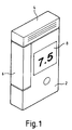
- the test device shown in Figure 1 comprises a housing 2 which has a lid 4 connected thereto by a hinge.
- the housing 2 has a display 8 for displaying an output of a test reading.
- the dimensions of the housing illustrated are about 90 mm by 50 mm by 15 mm.
- a sensor cutting member 6 is mounted on the housing 2.
- the sensor cutting member 6 is urged upwards by spring means (not shown) to an extended position as shown in Figure 2.
- spring means not shown
- the sensor cutting member 6 is provided with a blade 28 along its top inside edge which severs any sensor 10 which is disposed beneath the blade 28 when the lid 4 is closed.
- a sensor (test strip) 10, part of a reel 16 as shown in Figure 3, is disposed through a guide member 12 and is exposed in a test area to permit a blood sample to be applied to it.
- closing of the lid 4 causes the reel 16 to advance so that a used sensor 10' is disposed under the blade 28 for cutting and a fresh sensor 10 is exposed in the test area. Cut sensors 10' are collected in a container 34 in the housing 2.
- the reel 16 is made from 100 to 125 ⁇ m thick polyester tape. As shown in Figure 3 the reel 16 follows a path within the housing 2 from a spool 36 via a guide wheel 26 and ratchet wheel 22 to the test area at the top of the housing before the blade 28. Other arrangements and paths could of course be used and are within the scope of the invention. Sprocket holes 40 in the tape are engaged by sprockets 24 on the ratchet wheel 22 so that turning of the wheel 22 in a counter-clockwise direction as viewed in Figure 3 advances the reel 16. Sprocket holes could of course alternatively, or additionally, be provided along each edge of the tape in a well-known manner.
- the reel 16 could be provided as a removable cartridge which is loaded in the housing in the manner of loading a film in a camera, and it is within the scope of the invention to provide a motorised winding mechanism in the housing 2 for indexing the reel through the housing.
- Electronic signal processing means 18 are maintained in electrical contact with outer conductive tracks 38 on the reel 16 by means of contacts 44 in a connector 20, as best shown in Figure 8.
- Spring biasing means may be employed to help keep the contacts 44 permanently in contact with the reel 16.
- the reel 16 in Figure 8 has sprocket holes 40 around which the central conductive track is locally disposed. With this arrangement, the central contact 44 will be in electrical contact with the central conductive track only intermittently, when the central contact does not overlie a sprocket hole 40. It is therefore preferred that the path length between the test area and the contacts 44 is selected so that all three contacts 44 are in contact with all three conductive tracks 38 when a test strip 10 is ready for use in the test area.
- edge sprockets instead of central sprockets, or notches 46 in the edge of the reel 16 as shown in Figure 9.
- the notches 46 are engaged by suitable sprockets and provide points of weakness where the reel may be cut or torn.
- Figure 10 illustrates a two-electrode reel 16 with non-circular sprocket holes 40. This system does not, of course, require a third (central) contact. Lines of weakness 41 are provided in the reel to facilitate tearing off of used sensors.
- the signal processing electronics 18 are of course also connected to the display 8 for displaying an output which corresponds to the concentration of analyte (for example glucose) in a fluid sample (for example blood) applied to a sensor 10 at the test area.
- the signal processing means 18 and the display 8 together comprise the meter which produces a signal output which is dependent on the electrical signal from the sensors 10.
- Each sensor 10 (an example of which is shown in Figure 8 between broken lines) comprises a pair of electrodes 42, one of which functions as a working electrode and the other of which is a dummy electrode.
- a central conductive track 38 functions as a reference/counter electrode.
- the reel 16 has 100 sensors 10, all of which sensors are connected together by means of the conductive tracks 38, so that application of an analyte in a fluid sample to any sensor 10 on the reel 16 will produce an electrical signal which is sensed by the signal processing means 18. Since fluid samples are applied only at the test area, which is a fixed distance from the point of contact of the conductive tracks 38 with the contacts 44, the signal processing means may readily be calibrated to produce a display output which corresponds to the concentration of analyte in an applied sample, taking into account factors such as the resistance of the tracks between the two points.
- the ratchet wheel 22 has a plurality of ratchet teeth 32 radially disposed about one face.
- the hinged lid 4 is provided with a pawl 30 which is pivotally attached such that the act of closing the lid 4 causes the head of the pawl 30 to engage with and move a ratchet tooth 32, thereby causing the wheel 22 to move counter-clockwise as viewed in the drawings and advance the reel 16 by a distance corresponding to one sensor 10.
- Fully closing the lid 4 then causes the cutting blade 28 on the sensor cutter 6 to cut off a used sensor 10' as previously described.
- the pawl 30 drops back to the position shown in Figure 7, without moving the wheel 22, and the indexing process can then be repeated.
- Figure 7 shows another embodiment, in which the sprocket wheel 22 is provided with a drive wheel 52 whereby turning the drive wheel turns the sprocket wheel.
- a pawl 30 is pivotally connected to the lower portion of a lid 4 which has a central pivot 54. When a user fully depresses the lower part of the lid 4, the pawl 30 pushes a ratchet tooth 32 on the drive wheel 52 to index the reel by the length of one sensor. After taking a sample reading, the user pushes the upper part of the lid 4 so that a blade 28 cuts the used sensor from the reel 16.
- a notch or die 56 is provided in a surface under the reel 16 and co-operates with the blade 28 to aid cutting or tearing of the sensor 10.
- Figure 7a shows an optional arrangement for storing the reel 16 on a rotatable drum 60.
- the tail of the reel 16 is fixed to a core 58. Electrical contacts (not shown) on the core 58 are permanently connected to the conductive tracks on the reel 16.
- the reel As the reel is advanced by the sprocket drive, it unwinds from the outside of the rotatable drum 60.
- the tail end of the reel unwinds inside the drum, from a small radius around the fixed core to a larger radius, with fewer turns.
- FIG 14 another alternative arrangement is shown, similar to the feeding and cutting mechanism shown in Figure 7. Opening the lid 4 ( Figure 14a) turns the ratchet wheel 22 and moves a fresh sensor into the test area. Closing the lid ( Figure 14a) cuts off the used sensor by means of a blade 28, and the used sensor 10' drops into a waste container 34.
- the container 34 has one or more antibacterial agents to reduce odours.
- the device shown schematically in Figure 11 is a fully integrated unit which is disposed of when used.
- the unit comprises a PCB with signal processing electronics 18, a display 8, a battery 66, an optional waste sensor container 34, a reel storage area 62 and a feed mechanism 22 (optionally with a sensor detaching mechanism).
- the device of Figure 12 has the same component elements, but the reel is stored in a cassette or cartridge 64 which is removable. The reel may be wound on to the feed mechanism 22 automatically by a feed mechanism powered by the battery, or manually, in the manner of a camera wind-on mechanism.
- the device shown in Figure 13 features a cassette system in which both the reel storage area 62 and the feed mechanism 22 (and optionally the cutting mechanism) are housed in the cassette 64.
- the cassette 64 could also house the used sensors.
- the waste sensor container 34 could be provided with a take-up spool on which would be wound the reel 16 after use.
Landscapes
- Health & Medical Sciences (AREA)
- Engineering & Computer Science (AREA)
- Life Sciences & Earth Sciences (AREA)
- Biomedical Technology (AREA)
- Physics & Mathematics (AREA)
- Chemical & Material Sciences (AREA)
- Medicinal Chemistry (AREA)
- General Physics & Mathematics (AREA)
- Molecular Biology (AREA)
- Urology & Nephrology (AREA)
- Optics & Photonics (AREA)
- Food Science & Technology (AREA)
- Hematology (AREA)
- Biochemistry (AREA)
- Biophysics (AREA)
- General Health & Medical Sciences (AREA)
- Analytical Chemistry (AREA)
- Immunology (AREA)
- Pathology (AREA)
- Automatic Analysis And Handling Materials Therefor (AREA)
- Investigating Or Analysing Biological Materials (AREA)
Claims (16)
- Dispositif de test pour tester la concentration d'un analyte dans un fluide devant être appliqué à ce dispositif, le dispositif comprenant :une pluralité de capteurs (10) sur une bobine (16), chacun desdits capteurs (10) portant des moyens réactifs pour produire un signal électrique en réponse à la concentration d'un analyte dans un fluide appliqué, et chacun desdits capteurs (10) possédant une pluralité d'électrodes (42), des électrodes correspondantes (42) de capteurs adjacents (10) étant connectées entre eux par une piste conductrice (38) sur la bobine (16); etun appareil de mesure comprenant des moyens électroniques (18) pour produire un signal de sortie, qui dépend du signal électrique délivré par lesdits capteurs (10), l'appareil de mesure comprenant des contacts (44), qui sont connectés électriquement auxdites pistes conductrices (38), et une zone de test pour l'application d'un échantillon aux capteurs (10);
dans lequel les contacts (44) restent dans une position fixe par rapport à la zone de test lorsque la bobine (16) avance. - Dispositif de test selon la revendication 1, dans lequel l'appareil de mesure comporte des contacts (44) qui sont connectés de façon permanente auxdites pistes conductrices (38).
- Dispositif de test selon la revendication 1 ou la revendication 2, comprenant en outre des moyens de séparation (28) pour séparer un capteur utilisé (10') d'une extrémité de la bobine (16).
- Dispositif de test selon la revendication 3, dans lequel les moyens de séparation (28) comprennent des moyens de coupe pour couper la bobine (16).
- Dispositif de test selon la revendication 3 ou la revendication 4, dans lequel un capteur (10) est exposé de manière à permettre l'application d'un échantillon de fluide dans la zone de test, qui se situe à l'intérieur d'un boîtier (2), le boîtier (2) comportant un couvercle (4) qui peut être déplacé de manière à recouvrir la zone de test.
- Dispositif de test selon la revendication 5, dans lequel le déplacement du couvercle (4) depuis une position ouverte vers une position fermée fait avancer la bobine (16) de manière à positionner un capteur neuf (10) dans la zone de test.
- Dispositif de test selon la revendication 5 ou la revendication 6, dans lequel la fermeture du couvercle (4) amène les moyens de séparation (28) à fonctionner de façon à séparer un capteur utilisé (10') d'une extrémité de la bobine (16).
- Dispositif de test selon la revendication 6, dans lequel le déplacement du couvercle (4) fait avancer la bobine (16) à l'aide d'un mécanisme à cliquet (22,30,32).
- Dispositif de test selon la revendication 5, dans lequel le couvercle (4) est monté de manière à pouvoir pivoter par rapport au boîtier (2), le pivotement du couvercle (4) dans une direction amenant la bobine (16) à avancer de sorte qu'un capteur neuf (10) est présenté dans la zone de test, et un pivotement du couvercle (4) dans une autre direction entraînant une séparation de ce capteur par rapport à l'extrémité de la bobine (16).
- Dispositif de test selon l'une quelconque des revendications précédentes, dans lequel la bobine (16) est enroulée autour d'un tambour rotatif (60).
- Dispositif de test selon l'une quelconque des revendications 5 à 10, dans lequel un conteneur (34) est prévu dans le boîtier (2) pour recevoir des capteurs (10'), qui ont été séparés de la bobine (16).
- Dispositif de test selon la revendication 11, dans lequel le conteneur (34) peut être retiré du boîtier (2).
- Dispositif de test selon l'une quelconque des revendications précédentes, dans lequel l'appareil de mesure est logé dans un boîtier (2) et la bobine (16) est prévue dans une cartouche amovible (64) qui est montée par rapport au boîtier (2).
- Cartouche (64) destinée à être montée de façon amovible par rapport au boîtier (2) d'un dispositif de test selon la revendication 13, comprenant une pluralité de capteurs (10) situés sur une bobine (16), chacun desdits capteurs (10) portant des moyens réactifs pour produire un signal électrique en réponse à la concentration d'un analyte dans un fluide appliqué, et chacun desdits capteurs (10) possédant une pluralité d'électrodes (42), des électrodes correspondantes (42) de capteurs adjacents (10) étant connectées entre elles par une piste conductrice (38) sur la bobine (16); auquel cas lorsque la cartouche (64) est montée par rapport audit boîtier (2), la surface, au niveau de laquelle les pistes conductrices (38) situées sur la bobine (16) touchent les contacts (94), reste à une distance fixée de la zone de test lorsque la bobine (16) avance.
- Cartouche (16) selon la revendication 14, comprenant en outre un mécanisme pour dérouler et faire avancer la bobine lorsque la cartouche (64) est montée dans le boîtier (2) d'un dispositif de test.
- Cartouche (64) selon la revendication 14 ou la revendication 15, incluant en outre des moyens de mémoire (34) pour stocker des capteurs utilisés (10').
Priority Applications (1)
| Application Number | Priority Date | Filing Date | Title |
|---|---|---|---|
| AT99949102T ATE317976T1 (de) | 1999-09-27 | 1999-09-27 | Prüfvorrichtung |
Applications Claiming Priority (1)
| Application Number | Priority Date | Filing Date | Title |
|---|---|---|---|
| PCT/GB1999/003004 WO2001023885A1 (fr) | 1999-09-27 | 1999-09-27 | Dispositif d'analyse |
Publications (2)
| Publication Number | Publication Date |
|---|---|
| EP1216416A1 EP1216416A1 (fr) | 2002-06-26 |
| EP1216416B1 true EP1216416B1 (fr) | 2006-02-15 |
Family
ID=10847490
Family Applications (1)
| Application Number | Title | Priority Date | Filing Date |
|---|---|---|---|
| EP99949102A Expired - Lifetime EP1216416B1 (fr) | 1999-09-27 | 1999-09-27 | Dispositif d'analyse |
Country Status (5)
| Country | Link |
|---|---|
| EP (1) | EP1216416B1 (fr) |
| JP (1) | JP4256094B2 (fr) |
| AU (1) | AU6210199A (fr) |
| DE (1) | DE69929895T2 (fr) |
| WO (1) | WO2001023885A1 (fr) |
Families Citing this family (88)
| Publication number | Priority date | Publication date | Assignee | Title |
|---|---|---|---|---|
| US8641644B2 (en) | 2000-11-21 | 2014-02-04 | Sanofi-Aventis Deutschland Gmbh | Blood testing apparatus having a rotatable cartridge with multiple lancing elements and testing means |
| JP4522014B2 (ja) * | 2001-04-18 | 2010-08-11 | パナソニック株式会社 | バイオセンサシート、バイオセンサカートリッジ、およびバイオセンサ分与装置 |
| US9427532B2 (en) | 2001-06-12 | 2016-08-30 | Sanofi-Aventis Deutschland Gmbh | Tissue penetration device |
| US9795747B2 (en) | 2010-06-02 | 2017-10-24 | Sanofi-Aventis Deutschland Gmbh | Methods and apparatus for lancet actuation |
| DE60234598D1 (de) | 2001-06-12 | 2010-01-14 | Pelikan Technologies Inc | Selbstoptimierende lanzettenvorrichtung mit adaptationsmittel für zeitliche schwankungen von hauteigenschaften |
| AU2002320094A1 (en) | 2001-06-12 | 2002-12-23 | Pelikan Technologies, Inc. | Integrated blood sampling analysis system with multi-use sampling module |
| US9226699B2 (en) | 2002-04-19 | 2016-01-05 | Sanofi-Aventis Deutschland Gmbh | Body fluid sampling module with a continuous compression tissue interface surface |
| US7025774B2 (en) | 2001-06-12 | 2006-04-11 | Pelikan Technologies, Inc. | Tissue penetration device |
| US7323141B2 (en) | 2001-08-13 | 2008-01-29 | Bayer Healthcare Llc | Button layout for a testing instrument |
| AU2002300223B2 (en) * | 2001-08-13 | 2008-12-11 | Bayer Corporation | Mechanical Mechanism for a Blood Glucose Sensor Dispensing Instrument |
| JP4618953B2 (ja) * | 2001-09-13 | 2011-01-26 | パナソニック株式会社 | バイオセンサシート、バイオセンサカートリッジ、及び、バイオセンサ分与装置 |
| US7344894B2 (en) | 2001-10-16 | 2008-03-18 | Agilent Technologies, Inc. | Thermal regulation of fluidic samples within a diagnostic cartridge |
| US6997343B2 (en) | 2001-11-14 | 2006-02-14 | Hypoguard Limited | Sensor dispensing device |
| US6881578B2 (en) | 2002-04-02 | 2005-04-19 | Lifescan, Inc. | Analyte concentration determination meters and methods of using the same |
| US7172728B2 (en) | 2002-04-02 | 2007-02-06 | Lifescan, Inc. | Test strip containers and methods of using the same |
| US7901362B2 (en) | 2002-04-19 | 2011-03-08 | Pelikan Technologies, Inc. | Method and apparatus for penetrating tissue |
| US7371247B2 (en) | 2002-04-19 | 2008-05-13 | Pelikan Technologies, Inc | Method and apparatus for penetrating tissue |
| US7297122B2 (en) | 2002-04-19 | 2007-11-20 | Pelikan Technologies, Inc. | Method and apparatus for penetrating tissue |
| US7491178B2 (en) | 2002-04-19 | 2009-02-17 | Pelikan Technologies, Inc. | Method and apparatus for penetrating tissue |
| US7374544B2 (en) | 2002-04-19 | 2008-05-20 | Pelikan Technologies, Inc. | Method and apparatus for penetrating tissue |
| US9314194B2 (en) | 2002-04-19 | 2016-04-19 | Sanofi-Aventis Deutschland Gmbh | Tissue penetration device |
| US7547287B2 (en) | 2002-04-19 | 2009-06-16 | Pelikan Technologies, Inc. | Method and apparatus for penetrating tissue |
| US7674232B2 (en) | 2002-04-19 | 2010-03-09 | Pelikan Technologies, Inc. | Method and apparatus for penetrating tissue |
| US8784335B2 (en) | 2002-04-19 | 2014-07-22 | Sanofi-Aventis Deutschland Gmbh | Body fluid sampling device with a capacitive sensor |
| US7175642B2 (en) | 2002-04-19 | 2007-02-13 | Pelikan Technologies, Inc. | Methods and apparatus for lancet actuation |
| US8267870B2 (en) | 2002-04-19 | 2012-09-18 | Sanofi-Aventis Deutschland Gmbh | Method and apparatus for body fluid sampling with hybrid actuation |
| US7717863B2 (en) | 2002-04-19 | 2010-05-18 | Pelikan Technologies, Inc. | Method and apparatus for penetrating tissue |
| US7244265B2 (en) | 2002-04-19 | 2007-07-17 | Pelikan Technologies, Inc. | Method and apparatus for penetrating tissue |
| US8579831B2 (en) | 2002-04-19 | 2013-11-12 | Sanofi-Aventis Deutschland Gmbh | Method and apparatus for penetrating tissue |
| US7229458B2 (en) | 2002-04-19 | 2007-06-12 | Pelikan Technologies, Inc. | Method and apparatus for penetrating tissue |
| US7485128B2 (en) | 2002-04-19 | 2009-02-03 | Pelikan Technologies, Inc. | Method and apparatus for penetrating tissue |
| US7198606B2 (en) | 2002-04-19 | 2007-04-03 | Pelikan Technologies, Inc. | Method and apparatus for a multi-use body fluid sampling device with analyte sensing |
| US7410468B2 (en) | 2002-04-19 | 2008-08-12 | Pelikan Technologies, Inc. | Method and apparatus for penetrating tissue |
| US7232451B2 (en) | 2002-04-19 | 2007-06-19 | Pelikan Technologies, Inc. | Method and apparatus for penetrating tissue |
| US7648468B2 (en) | 2002-04-19 | 2010-01-19 | Pelikon Technologies, Inc. | Method and apparatus for penetrating tissue |
| US9248267B2 (en) | 2002-04-19 | 2016-02-02 | Sanofi-Aventis Deustchland Gmbh | Tissue penetration device |
| US7291117B2 (en) | 2002-04-19 | 2007-11-06 | Pelikan Technologies, Inc. | Method and apparatus for penetrating tissue |
| US7563232B2 (en) | 2002-04-19 | 2009-07-21 | Pelikan Technologies, Inc. | Method and apparatus for penetrating tissue |
| US7524293B2 (en) | 2002-04-19 | 2009-04-28 | Pelikan Technologies, Inc. | Method and apparatus for penetrating tissue |
| US7141058B2 (en) | 2002-04-19 | 2006-11-28 | Pelikan Technologies, Inc. | Method and apparatus for a body fluid sampling device using illumination |
| US7331931B2 (en) | 2002-04-19 | 2008-02-19 | Pelikan Technologies, Inc. | Method and apparatus for penetrating tissue |
| US9795334B2 (en) | 2002-04-19 | 2017-10-24 | Sanofi-Aventis Deutschland Gmbh | Method and apparatus for penetrating tissue |
| US7258693B2 (en) | 2002-04-19 | 2007-08-21 | Pelikan Technologies, Inc. | Device and method for variable speed lancet |
| US8702624B2 (en) | 2006-09-29 | 2014-04-22 | Sanofi-Aventis Deutschland Gmbh | Analyte measurement device with a single shot actuator |
| US7303726B2 (en) | 2002-05-09 | 2007-12-04 | Lifescan, Inc. | Minimal procedure analyte test system |
| US7343188B2 (en) | 2002-05-09 | 2008-03-11 | Lifescan, Inc. | Devices and methods for accessing and analyzing physiological fluid |
| US20030223906A1 (en) * | 2002-06-03 | 2003-12-04 | Mcallister Devin | Test strip container system |
| US7250095B2 (en) | 2002-07-11 | 2007-07-31 | Hypoguard Limited | Enzyme electrodes and method of manufacture |
| US8574895B2 (en) | 2002-12-30 | 2013-11-05 | Sanofi-Aventis Deutschland Gmbh | Method and apparatus using optical techniques to measure analyte levels |
| US7264139B2 (en) | 2003-01-14 | 2007-09-04 | Hypoguard Limited | Sensor dispensing device |
| WO2006001797A1 (fr) | 2004-06-14 | 2006-01-05 | Pelikan Technologies, Inc. | Element penetrant peu douloureux |
| US7604592B2 (en) | 2003-06-13 | 2009-10-20 | Pelikan Technologies, Inc. | Method and apparatus for a point of care device |
| US8282576B2 (en) | 2003-09-29 | 2012-10-09 | Sanofi-Aventis Deutschland Gmbh | Method and apparatus for an improved sample capture device |
| EP1680014A4 (fr) | 2003-10-14 | 2009-01-21 | Pelikan Technologies Inc | Procede et appareil fournissant une interface-utilisateur variable |
| DE10348283A1 (de) | 2003-10-17 | 2005-05-12 | Roche Diagnostics Gmbh | Handgerät zur Untersuchung einer Körperflüssigkeit |
| DE10361261B4 (de) * | 2003-12-24 | 2006-02-09 | Roche Diagnostics Gmbh | Analysehandgerät |
| US8147426B2 (en) * | 2003-12-31 | 2012-04-03 | Nipro Diagnostics, Inc. | Integrated diagnostic test system |
| EP1706026B1 (fr) | 2003-12-31 | 2017-03-01 | Sanofi-Aventis Deutschland GmbH | Procédé et appareil permettant d'améliorer le flux fluidique et le prélèvement d'échantillons |
| WO2006011062A2 (fr) | 2004-05-20 | 2006-02-02 | Albatros Technologies Gmbh & Co. Kg | Hydrogel imprimable pour biocapteurs |
| WO2005120365A1 (fr) | 2004-06-03 | 2005-12-22 | Pelikan Technologies, Inc. | Procede et appareil pour la fabrication d'un dispositif d'echantillonnage de liquides |
| US9775553B2 (en) | 2004-06-03 | 2017-10-03 | Sanofi-Aventis Deutschland Gmbh | Method and apparatus for a fluid sampling device |
| WO2006059241A2 (fr) * | 2004-11-05 | 2006-06-08 | Albatros Technologies Gmbh & Co. Kg | Dispositif de detection d'analytes monte sur un substrat flexible |
| DE102005013685A1 (de) | 2005-03-18 | 2006-09-28 | Roche Diagnostics Gmbh | Bandmagazin für ein Handgerät zur Untersuchung einer Körperflüssigkeit, sowie Handgerät |
| US7516847B2 (en) * | 2005-06-14 | 2009-04-14 | Roche Diagnostics Operations, Inc. | Biocidal blood glucose strip and lancet or sharps disposal device |
| EP1736772B1 (fr) | 2005-06-22 | 2016-05-18 | F.Hoffmann-La Roche Ag | Dispositif de test avec un dispositif de stockage d'éléments d'analyse |
| EP1815785A1 (fr) * | 2006-02-02 | 2007-08-08 | Bioception B.V.i.o. | Dispositif en forme d'une cassette pour le diagnostic de fluides |
| US7638095B2 (en) * | 2006-02-10 | 2009-12-29 | Roche Diagnostics Operations, Inc. | Personal portable blood glucose meter with replaceable cartridge of test strips |
| WO2007096832A1 (fr) | 2006-02-23 | 2007-08-30 | Agamatrix, Inc | Contenant pour stockage de bâtonnets diagnostiques usagés |
| US8388905B2 (en) | 2006-03-13 | 2013-03-05 | Nipro Diagnostics, Inc. | Method and apparatus for coding diagnostic meters |
| US11559810B2 (en) | 2006-03-13 | 2023-01-24 | Trividia Health, Inc. | Method and apparatus for coding diagnostic meters |
| US8388906B2 (en) | 2006-03-13 | 2013-03-05 | Nipro Diagnostics, Inc. | Apparatus for dispensing test strips |
| US8940246B2 (en) | 2006-03-13 | 2015-01-27 | Nipro Diagnostics, Inc. | Method and apparatus for coding diagnostic meters |
| CA2650759C (fr) * | 2006-05-01 | 2011-11-22 | Hans List | Dispositif d'analyse d'un echantillon de fluide a rouleau et ruban d'analyse |
| EP1852699A1 (fr) | 2006-05-06 | 2007-11-07 | F.Hoffmann-La Roche Ag | Unité d'analyse diagnostique avec un réservoir de supports d'essai |
| US8155925B2 (en) * | 2006-06-28 | 2012-04-10 | Koninklijke Philips Electronics N.V. | Disposable assay device with removables modules and remote data transfer system |
| WO2009126900A1 (fr) | 2008-04-11 | 2009-10-15 | Pelikan Technologies, Inc. | Procédé et appareil pour dispositif de détection d’analyte |
| EP2177155A1 (fr) * | 2008-10-20 | 2010-04-21 | F. Hoffmann-Roche AG | Instrument de bande de test analytique avec moteur à courant continu et engrenage |
| US9375169B2 (en) | 2009-01-30 | 2016-06-28 | Sanofi-Aventis Deutschland Gmbh | Cam drive for managing disposable penetrating member actions with a single motor and motor and control system |
| EP2221001A1 (fr) * | 2009-02-18 | 2010-08-25 | Roche Diagnostics GmbH | Appareil manuel d'analyse |
| EP2357473A1 (fr) * | 2010-01-26 | 2011-08-17 | F. Hoffmann-La Roche AG | Système de bande destiné à l'analyse d'échantillons |
| US8965476B2 (en) | 2010-04-16 | 2015-02-24 | Sanofi-Aventis Deutschland Gmbh | Tissue penetration device |
| EP2466304A1 (fr) * | 2010-12-16 | 2012-06-20 | Roche Diagnostics GmbH | Dispositif de bande de test |
| WO2013096268A1 (fr) | 2011-12-20 | 2013-06-27 | Bayer Heal Thcare Llc | Système linéaire de mesure du glucose à base de cartouche |
| US9097700B2 (en) | 2011-12-29 | 2015-08-04 | Bayer Healthcare Llc | Glucose measurement system with high-capacity cartridge and capability of more frequent replenishment |
| US9204829B2 (en) | 2012-05-31 | 2015-12-08 | Bayer Healthcare Llc | Multistrip cartridge |
| EP2856168B1 (fr) | 2012-05-31 | 2018-01-10 | Ascensia Diabetes Care Holdings AG | Cartouche à multibande remplaçable et dispositif de mesure à biocapteur |
| EP2953540B1 (fr) * | 2013-02-11 | 2016-12-07 | Roche Diabetes Care GmbH | Instrument médical portatif pour analyse de liquide corporel |
| CN105209908B (zh) | 2013-03-12 | 2018-01-09 | 安晟信医疗科技控股公司 | 具有用于推动测试条紧靠光学读出器的机构的测试条计量仪 |
Family Cites Families (6)
| Publication number | Priority date | Publication date | Assignee | Title |
|---|---|---|---|---|
| EP0373413A1 (fr) * | 1988-12-13 | 1990-06-20 | Daikin Industries, Limited | Appareil d'assistance, appareil de test et méthode pour mesurer la concentration d'une substance dans un liquide |
| FR2701117B1 (fr) * | 1993-02-04 | 1995-03-10 | Asulab Sa | Système de mesures électrochimiques à capteur multizones, et son application au dosage du glucose. |
| FR2705150B1 (fr) * | 1993-05-10 | 1995-07-21 | Asulab Sa | Capteur électrochimique à zones multiples sur disque et son application au dosage du glucose. |
| FR2710411B1 (fr) * | 1993-09-21 | 1995-11-17 | Asulab Sa | Dispositif de mesure pour capteurs multizones amovibles. |
| US5630986A (en) * | 1995-01-13 | 1997-05-20 | Bayer Corporation | Dispensing instrument for fluid monitoring sensors |
| FR2733745B1 (fr) * | 1995-05-02 | 1997-07-04 | Asulab Sa | Appareil perfectionne destine a la ditribution de zones successives d'une bande consommable |
-
1999
- 1999-09-27 EP EP99949102A patent/EP1216416B1/fr not_active Expired - Lifetime
- 1999-09-27 WO PCT/GB1999/003004 patent/WO2001023885A1/fr not_active Ceased
- 1999-09-27 JP JP2001527221A patent/JP4256094B2/ja not_active Expired - Fee Related
- 1999-09-27 DE DE69929895T patent/DE69929895T2/de not_active Expired - Lifetime
- 1999-09-27 AU AU62101/99A patent/AU6210199A/en not_active Abandoned
Also Published As
| Publication number | Publication date |
|---|---|
| AU6210199A (en) | 2001-04-30 |
| EP1216416A1 (fr) | 2002-06-26 |
| WO2001023885A8 (fr) | 2001-12-13 |
| JP4256094B2 (ja) | 2009-04-22 |
| WO2001023885A1 (fr) | 2001-04-05 |
| DE69929895T2 (de) | 2006-08-24 |
| DE69929895D1 (de) | 2006-04-20 |
| JP2003510606A (ja) | 2003-03-18 |
Similar Documents
| Publication | Publication Date | Title |
|---|---|---|
| EP1216416B1 (fr) | Dispositif d'analyse | |
| EP1360935B1 (fr) | Band contenant des appareils pour la collecte et l'analyse d'échantillons de fluid et méthodes pour la produire, l'utiliser et l'emballer | |
| EP0732590B1 (fr) | Dispensateur des capteurs pour l'analyse des liquides | |
| US7378270B2 (en) | Device for analyte measurement | |
| EP1530722B1 (fr) | Appareil d'analyse d' chantillons int gr | |
| JP4689727B2 (ja) | 分析用具パック、および分析装置 | |
| JP3980444B2 (ja) | プル/プッシュ起動機構を有する血中グルコースセンサ分与装置 | |
| JP4049634B2 (ja) | モジュール電子機器アセンブリを有する血中グルコースセンサ分与装置 | |
| CN101237815B (zh) | 用于监测体液的集成测试系统 | |
| JP2003130836A (ja) | 血中グルコースセンサ分与装置用の機構 | |
| JPH0752170B2 (ja) | 拡散制限膜保持具収容容器 | |
| JP4522014B2 (ja) | バイオセンサシート、バイオセンサカートリッジ、およびバイオセンサ分与装置 | |
| JP2006297103A (ja) | 分析補助手段 | |
| CA2637781A1 (fr) | Glucometre personnel portable dote d'une cartouche remplacable de bandes test | |
| JP4443718B2 (ja) | 生体試料測定装置 | |
| EP2122345A1 (fr) | Instruments de contrôle d'analyte | |
| JP2003083927A (ja) | バイオセンサ、バイオセンサシート、バイオセンサカートリッジ、及び、バイオセンサ分与装置 | |
| EP1877191B1 (fr) | Mécanisme de libération de capteur pour un instrument de mesure | |
| KR100975788B1 (ko) | 통합형 샘플 시험 측정계용 카트리지 장치 및 방법 | |
| JP2003215085A (ja) | バイオセンサ分与装置 | |
| EP1940283A2 (fr) | Outil de diagnostic integre a couvercle a charnieres | |
| HK1057687B (en) | Strip containing a series of fluid sampling and testing devices and method of making, packaging and using it | |
| HK1076147B (en) | Integrated sample testing meter |
Legal Events
| Date | Code | Title | Description |
|---|---|---|---|
| PUAI | Public reference made under article 153(3) epc to a published international application that has entered the european phase |
Free format text: ORIGINAL CODE: 0009012 |
|
| 17P | Request for examination filed |
Effective date: 20020301 |
|
| AK | Designated contracting states |
Kind code of ref document: A1 Designated state(s): AT BE CH CY DE DK ES FI FR GB GR IE IT LI LU MC NL PT SE |
|
| AX | Request for extension of the european patent |
Free format text: AL;LT;LV;MK;RO;SI |
|
| 17Q | First examination report despatched |
Effective date: 20040617 |
|
| GRAP | Despatch of communication of intention to grant a patent |
Free format text: ORIGINAL CODE: EPIDOSNIGR1 |
|
| GRAS | Grant fee paid |
Free format text: ORIGINAL CODE: EPIDOSNIGR3 |
|
| GRAA | (expected) grant |
Free format text: ORIGINAL CODE: 0009210 |
|
| AK | Designated contracting states |
Kind code of ref document: B1 Designated state(s): AT BE CH CY DE DK ES FI FR GB GR IE IT LI LU MC NL PT SE |
|
| PG25 | Lapsed in a contracting state [announced via postgrant information from national office to epo] |
Ref country code: NL Free format text: LAPSE BECAUSE OF FAILURE TO SUBMIT A TRANSLATION OF THE DESCRIPTION OR TO PAY THE FEE WITHIN THE PRESCRIBED TIME-LIMIT Effective date: 20060215 Ref country code: LI Free format text: LAPSE BECAUSE OF FAILURE TO SUBMIT A TRANSLATION OF THE DESCRIPTION OR TO PAY THE FEE WITHIN THE PRESCRIBED TIME-LIMIT Effective date: 20060215 Ref country code: FI Free format text: LAPSE BECAUSE OF FAILURE TO SUBMIT A TRANSLATION OF THE DESCRIPTION OR TO PAY THE FEE WITHIN THE PRESCRIBED TIME-LIMIT Effective date: 20060215 Ref country code: CH Free format text: LAPSE BECAUSE OF FAILURE TO SUBMIT A TRANSLATION OF THE DESCRIPTION OR TO PAY THE FEE WITHIN THE PRESCRIBED TIME-LIMIT Effective date: 20060215 Ref country code: BE Free format text: LAPSE BECAUSE OF FAILURE TO SUBMIT A TRANSLATION OF THE DESCRIPTION OR TO PAY THE FEE WITHIN THE PRESCRIBED TIME-LIMIT Effective date: 20060215 Ref country code: AT Free format text: LAPSE BECAUSE OF FAILURE TO SUBMIT A TRANSLATION OF THE DESCRIPTION OR TO PAY THE FEE WITHIN THE PRESCRIBED TIME-LIMIT Effective date: 20060215 |
|
| REG | Reference to a national code |
Ref country code: GB Ref legal event code: FG4D Ref country code: CH Ref legal event code: EP |
|
| REG | Reference to a national code |
Ref country code: IE Ref legal event code: FG4D |
|
| REF | Corresponds to: |
Ref document number: 69929895 Country of ref document: DE Date of ref document: 20060420 Kind code of ref document: P |
|
| PG25 | Lapsed in a contracting state [announced via postgrant information from national office to epo] |
Ref country code: SE Free format text: LAPSE BECAUSE OF FAILURE TO SUBMIT A TRANSLATION OF THE DESCRIPTION OR TO PAY THE FEE WITHIN THE PRESCRIBED TIME-LIMIT Effective date: 20060515 Ref country code: DK Free format text: LAPSE BECAUSE OF FAILURE TO SUBMIT A TRANSLATION OF THE DESCRIPTION OR TO PAY THE FEE WITHIN THE PRESCRIBED TIME-LIMIT Effective date: 20060515 |
|
| PG25 | Lapsed in a contracting state [announced via postgrant information from national office to epo] |
Ref country code: ES Free format text: LAPSE BECAUSE OF FAILURE TO SUBMIT A TRANSLATION OF THE DESCRIPTION OR TO PAY THE FEE WITHIN THE PRESCRIBED TIME-LIMIT Effective date: 20060526 |
|
| PG25 | Lapsed in a contracting state [announced via postgrant information from national office to epo] |
Ref country code: PT Free format text: LAPSE BECAUSE OF FAILURE TO SUBMIT A TRANSLATION OF THE DESCRIPTION OR TO PAY THE FEE WITHIN THE PRESCRIBED TIME-LIMIT Effective date: 20060717 |
|
| NLV1 | Nl: lapsed or annulled due to failure to fulfill the requirements of art. 29p and 29m of the patents act | ||
| REG | Reference to a national code |
Ref country code: CH Ref legal event code: PL |
|
| PG25 | Lapsed in a contracting state [announced via postgrant information from national office to epo] |
Ref country code: IE Free format text: LAPSE BECAUSE OF NON-PAYMENT OF DUE FEES Effective date: 20060927 |
|
| PG25 | Lapsed in a contracting state [announced via postgrant information from national office to epo] |
Ref country code: MC Free format text: LAPSE BECAUSE OF NON-PAYMENT OF DUE FEES Effective date: 20060930 |
|
| ET | Fr: translation filed | ||
| PLBE | No opposition filed within time limit |
Free format text: ORIGINAL CODE: 0009261 |
|
| STAA | Information on the status of an ep patent application or granted ep patent |
Free format text: STATUS: NO OPPOSITION FILED WITHIN TIME LIMIT |
|
| 26N | No opposition filed |
Effective date: 20061116 |
|
| PG25 | Lapsed in a contracting state [announced via postgrant information from national office to epo] |
Ref country code: GR Free format text: LAPSE BECAUSE OF FAILURE TO SUBMIT A TRANSLATION OF THE DESCRIPTION OR TO PAY THE FEE WITHIN THE PRESCRIBED TIME-LIMIT Effective date: 20060516 |
|
| PG25 | Lapsed in a contracting state [announced via postgrant information from national office to epo] |
Ref country code: LU Free format text: LAPSE BECAUSE OF NON-PAYMENT OF DUE FEES Effective date: 20060927 |
|
| PG25 | Lapsed in a contracting state [announced via postgrant information from national office to epo] |
Ref country code: CY Free format text: LAPSE BECAUSE OF FAILURE TO SUBMIT A TRANSLATION OF THE DESCRIPTION OR TO PAY THE FEE WITHIN THE PRESCRIBED TIME-LIMIT Effective date: 20060215 |
|
| REG | Reference to a national code |
Ref country code: FR Ref legal event code: PLFP Year of fee payment: 17 |
|
| PGFP | Annual fee paid to national office [announced via postgrant information from national office to epo] |
Ref country code: GB Payment date: 20150701 Year of fee payment: 17 |
|
| PGFP | Annual fee paid to national office [announced via postgrant information from national office to epo] |
Ref country code: FR Payment date: 20150630 Year of fee payment: 17 |
|
| PGFP | Annual fee paid to national office [announced via postgrant information from national office to epo] |
Ref country code: IT Payment date: 20150902 Year of fee payment: 17 |
|
| PGFP | Annual fee paid to national office [announced via postgrant information from national office to epo] |
Ref country code: DE Payment date: 20151110 Year of fee payment: 17 |
|
| REG | Reference to a national code |
Ref country code: DE Ref legal event code: R119 Ref document number: 69929895 Country of ref document: DE |
|
| GBPC | Gb: european patent ceased through non-payment of renewal fee |
Effective date: 20160927 |
|
| REG | Reference to a national code |
Ref country code: FR Ref legal event code: ST Effective date: 20170531 |
|
| PG25 | Lapsed in a contracting state [announced via postgrant information from national office to epo] |
Ref country code: FR Free format text: LAPSE BECAUSE OF NON-PAYMENT OF DUE FEES Effective date: 20160930 Ref country code: DE Free format text: LAPSE BECAUSE OF NON-PAYMENT OF DUE FEES Effective date: 20170401 Ref country code: GB Free format text: LAPSE BECAUSE OF NON-PAYMENT OF DUE FEES Effective date: 20160927 |
|
| PG25 | Lapsed in a contracting state [announced via postgrant information from national office to epo] |
Ref country code: IT Free format text: LAPSE BECAUSE OF NON-PAYMENT OF DUE FEES Effective date: 20160927 |