EP1216665A1 - Verfahren zum Anbringen eines Markerelements an einem Implantat - Google Patents
Verfahren zum Anbringen eines Markerelements an einem Implantat Download PDFInfo
- Publication number
- EP1216665A1 EP1216665A1 EP01250443A EP01250443A EP1216665A1 EP 1216665 A1 EP1216665 A1 EP 1216665A1 EP 01250443 A EP01250443 A EP 01250443A EP 01250443 A EP01250443 A EP 01250443A EP 1216665 A1 EP1216665 A1 EP 1216665A1
- Authority
- EP
- European Patent Office
- Prior art keywords
- recess
- base body
- implant
- material mixture
- marker
- Prior art date
- Legal status (The legal status is an assumption and is not a legal conclusion. Google has not performed a legal analysis and makes no representation as to the accuracy of the status listed.)
- Granted
Links
- 239000003550 marker Substances 0.000 title claims abstract description 72
- 239000007943 implant Substances 0.000 title claims abstract description 47
- 238000000034 method Methods 0.000 title claims abstract description 46
- 239000000463 material Substances 0.000 claims abstract description 63
- 239000000203 mixture Substances 0.000 claims abstract description 40
- 241001465754 Metazoa Species 0.000 claims abstract description 5
- 238000002513 implantation Methods 0.000 claims abstract description 5
- 239000008187 granular material Substances 0.000 claims description 36
- 230000009969 flowable effect Effects 0.000 claims description 15
- 238000005245 sintering Methods 0.000 claims description 8
- 238000007711 solidification Methods 0.000 claims description 8
- 230000008023 solidification Effects 0.000 claims description 8
- 230000005855 radiation Effects 0.000 claims description 6
- 239000000843 powder Substances 0.000 claims description 5
- 229910000497 Amalgam Inorganic materials 0.000 claims description 3
- 238000002604 ultrasonography Methods 0.000 claims description 2
- 238000004070 electrodeposition Methods 0.000 claims 2
- 239000002245 particle Substances 0.000 description 9
- 238000004519 manufacturing process Methods 0.000 description 8
- 238000010438 heat treatment Methods 0.000 description 5
- 239000004033 plastic Substances 0.000 description 5
- 229920003023 plastic Polymers 0.000 description 5
- 239000011248 coating agent Substances 0.000 description 4
- 238000000576 coating method Methods 0.000 description 4
- 239000007787 solid Substances 0.000 description 4
- 230000008021 deposition Effects 0.000 description 3
- 238000003384 imaging method Methods 0.000 description 3
- PCHJSUWPFVWCPO-UHFFFAOYSA-N gold Chemical compound [Au] PCHJSUWPFVWCPO-UHFFFAOYSA-N 0.000 description 2
- 239000010931 gold Substances 0.000 description 2
- 229910052737 gold Inorganic materials 0.000 description 2
- 238000002372 labelling Methods 0.000 description 2
- 235000011837 pasties Nutrition 0.000 description 2
- 238000003825 pressing Methods 0.000 description 2
- 238000000926 separation method Methods 0.000 description 2
- 239000000725 suspension Substances 0.000 description 2
- 230000002792 vascular Effects 0.000 description 2
- 238000003466 welding Methods 0.000 description 2
- 238000009825 accumulation Methods 0.000 description 1
- 239000000853 adhesive Substances 0.000 description 1
- 230000001070 adhesive effect Effects 0.000 description 1
- 239000000560 biocompatible material Substances 0.000 description 1
- 239000000919 ceramic Substances 0.000 description 1
- 238000005137 deposition process Methods 0.000 description 1
- 230000000694 effects Effects 0.000 description 1
- 239000012799 electrically-conductive coating Substances 0.000 description 1
- 230000005611 electricity Effects 0.000 description 1
- 230000008030 elimination Effects 0.000 description 1
- 238000003379 elimination reaction Methods 0.000 description 1
- 230000004927 fusion Effects 0.000 description 1
- 238000007654 immersion Methods 0.000 description 1
- 239000011344 liquid material Substances 0.000 description 1
- 238000002844 melting Methods 0.000 description 1
- 230000008018 melting Effects 0.000 description 1
- 239000002184 metal Substances 0.000 description 1
- 229910052751 metal Inorganic materials 0.000 description 1
- 229910001092 metal group alloy Inorganic materials 0.000 description 1
- 150000002739 metals Chemical class 0.000 description 1
- 230000003647 oxidation Effects 0.000 description 1
- 238000007254 oxidation reaction Methods 0.000 description 1
- 239000011253 protective coating Substances 0.000 description 1
- 230000001105 regulatory effect Effects 0.000 description 1
- 239000007966 viscous suspension Substances 0.000 description 1
- 238000010792 warming Methods 0.000 description 1
Images



Classifications
-
- A—HUMAN NECESSITIES
- A61—MEDICAL OR VETERINARY SCIENCE; HYGIENE
- A61F—FILTERS IMPLANTABLE INTO BLOOD VESSELS; PROSTHESES; DEVICES PROVIDING PATENCY TO, OR PREVENTING COLLAPSING OF, TUBULAR STRUCTURES OF THE BODY, e.g. STENTS; ORTHOPAEDIC, NURSING OR CONTRACEPTIVE DEVICES; FOMENTATION; TREATMENT OR PROTECTION OF EYES OR EARS; BANDAGES, DRESSINGS OR ABSORBENT PADS; FIRST-AID KITS
- A61F2/00—Filters implantable into blood vessels; Prostheses, i.e. artificial substitutes or replacements for parts of the body; Appliances for connecting them with the body; Devices providing patency to, or preventing collapsing of, tubular structures of the body, e.g. stents
- A61F2/82—Devices providing patency to, or preventing collapsing of, tubular structures of the body, e.g. stents
- A61F2/86—Stents in a form characterised by the wire-like elements; Stents in the form characterised by a net-like or mesh-like structure
-
- A—HUMAN NECESSITIES
- A61—MEDICAL OR VETERINARY SCIENCE; HYGIENE
- A61B—DIAGNOSIS; SURGERY; IDENTIFICATION
- A61B90/00—Instruments, implements or accessories specially adapted for surgery or diagnosis and not covered by any of the groups A61B1/00 - A61B50/00, e.g. for luxation treatment or for protecting wound edges
- A61B90/39—Markers, e.g. radio-opaque or breast lesions markers
-
- A—HUMAN NECESSITIES
- A61—MEDICAL OR VETERINARY SCIENCE; HYGIENE
- A61F—FILTERS IMPLANTABLE INTO BLOOD VESSELS; PROSTHESES; DEVICES PROVIDING PATENCY TO, OR PREVENTING COLLAPSING OF, TUBULAR STRUCTURES OF THE BODY, e.g. STENTS; ORTHOPAEDIC, NURSING OR CONTRACEPTIVE DEVICES; FOMENTATION; TREATMENT OR PROTECTION OF EYES OR EARS; BANDAGES, DRESSINGS OR ABSORBENT PADS; FIRST-AID KITS
- A61F2250/00—Special features of prostheses classified in groups A61F2/00 - A61F2/26 or A61F2/82 or A61F9/00 or A61F11/00 or subgroups thereof
- A61F2250/0058—Additional features; Implant or prostheses properties not otherwise provided for
- A61F2250/0096—Markers and sensors for detecting a position or changes of a position of an implant, e.g. RF sensors, ultrasound markers
- A61F2250/0098—Markers and sensors for detecting a position or changes of a position of an implant, e.g. RF sensors, ultrasound markers radio-opaque, e.g. radio-opaque markers
Definitions
- the present invention relates to a method for attaching a marker element on one for implantation in human or animal Body-provided implant, in particular a stent, with a Base body and a recess provided in this base body to accommodate the marker element. It also relates to an implant, in particular a stent which is provided with such a marker element is.
- a large number of currently used implants are used in human or animal body, for example with the aid of a catheter or The same is used without the surgeon directing the implantation site can see.
- markers are usually left on defined Positions attached to the implant. The material of these markers the more chosen that it gives a sufficiently high-contrast image impression, which Allows conclusions to be drawn about the position of the implant.
- Such markers usually consist of solids, which are used for Radiation used in imaging are opaque. Such a solid is inserted into the recess in the base body of the implant and with the base body by pressing and additionally or alternatively by Welding connected.
- a stent is known from WO 97/33534, in which individual X-ray-opaque marker elements made of gold in recesses in the base body of the stent are inserted and pressed with this to the mechanical Establish connection between marker element and stent body.
- the marker elements are partly also in the manner of a Rivet deformed.
- Similar x-ray markers for a stent are from the US 6,022,374. These have an excess compared to the recess on and are deformed by the delimiting the recess Stent material pressed into the recess.
- both variants have the disadvantage that the implant in the area of Recess when pressing, sometimes quite high mechanical loads is subject. Especially the relatively fragile structures, such as those Representing stents, this area can quickly become an undesirable one Damage to the base body. This is particularly harmful if it is not immediately recognizable and, if necessary, only in the implanted Condition fails. For example, with one Stent may come to unwanted sharp edges, which may even damage the surrounding tissue. Likewise, of course it can also to an undesired detachment of the marker element from the implant come.
- the marker element with the adjacent one Base body of the implant welded.
- the disadvantage that the recess and the marker element is made with a relatively precise fit need to ensure that there is a sufficient mechanical bond is achieved. This results in a relatively complex process for all of these variants Production.
- there is scope for all known variants the variation of the geometry of the marker or the recess under economic Aspects limited because of different recesses different markers must be produced.
- the present invention is based on the object, a generic Method for attaching a marker element to an implant and to provide a generic implant that the Do not have the above-mentioned disadvantages or at least to a lesser extent and in particular ensure simple and flexible production.
- This task is based on a method according to the preamble of claim 1 by the in the characterizing part of claim 1 specified features solved. It is also based on an implant according to the preamble of claim 9 by the in the characterizing Part of claim 9 specified features solved.
- the present invention is based on the technical teaching that one a particularly simple and flexible manufacture of an implant with a marker element arranged in a recess of the base body of the implant achieved if to form at least part of the marker element a solidifiable material or material mixture in the recess introduced and solidified there.
- the material or material mixture introduced is preferably a flowable or pourable material or material mixture. Due to the flowability or pourability of the solidifiable material used on the one hand it is ensured that the resulting Marker element easily to any geometry of the recess adapts. On the one hand, this has the consequence that it is particularly high There is flexibility in the design of the recesses and secondly no special dimensional tolerances or the like must be observed during their manufacture are. This considerably simplifies the manufacture of the implant.
- Another advantage of the solution according to the invention is that the Attach the marker element between excessive voltages the marker element and the adjacent base body of the implant occur so that neither the marker element nor the base body of the Implant excessive mechanical stress, especially high Are subjected to prestresses. The likelihood that it will Manufacture or in use for failure of the marker element or of the adjoining base body is thus opposite to that from the Known prior art variants significantly reduced.
- the material or material mixture used can be a trade any sufficiently biocompatible material or material mixture, which is sufficiently solidifiable to form a sufficiently stable marker element and a sufficiently secure bond between the marker element and the adjacent base body.
- the material or material mixture used preferably forms the entire marker element. To do this, it can consist of a single one accordingly solidifiable component exist, which is also an adequate Has impermeability to the radiation used for imaging.
- particles or larger parts of one accordingly radiation-impermeable material a corresponding solidifiable Material or material mixture are added.
- the pourable material or material mixture from one Granules the grains of which consist of one or more particles according to radiopaque material made by a solidifiable material or material mixture are enclosed.
- bigger ones can be Parts of such a radiation-impermeable material, in whole or in part be surrounded by a suitable solidifiable material.
- Another variant is flowable or pasty, solidifiable and corresponding radiation-opaque materials, such as that made of dentistry known amalgam, which without energy supply, d. H. harden cold. It goes without saying that these, of course, are also related with the mentioned enclosed or enclosed particles or Parts can be used.
- the flowable or pourable material or material mixture sinterable granulate or powder that is in the recess by sintering is solidified, since such granules or powder are particularly simple Allow handling.
- Draw advantageous embodiments of the method according to the invention is characterized in that the solidification process is an endothermic step comprises and at least part of the process energy in the endothermic Step is introduced locally in the area of the recess. This leaves a particularly targeted and easily controllable solidification in an advantageous manner with the result of both a stable marker element as well a stable connection between the marker element and the base body.
- the process energy can be in any, on the material to be solidified or material mixtures specifically introduced locally become. It is preferably targeted in the endothermic step Irradiation of the material arranged in the area of the recess or Mixed material introduced.
- a laser can be used because they are particularly easy and well targeted leaves.
- a powder or granulate can become mechanical Vibrations are excited, which are then due to the friction cause heating between the particles.
- Such a suggestion can be done, for example, using ultrasound.
- can also specifically shaped heating surfaces or heating elements or the like are used. These can be used in addition pressure on the material or material mixture to be solidified.
- stamps etc. for pressure generation can of course also in connection with the other variants of energy input be used.
- At least part of the process energy is in the endothermic step electrically by generating a current flow through the flowable or pourable material arranged in the region of the recess or mixed material introduced.
- the material or material mixture be chosen so that there is a large resistance to the current represents, with the result that in it a large part of the energy supplied is converted into heat.
- the present invention further relates to an implant, in particular one Stent, for implantation in the human or animal body with a manufactured or attached in the manner described above Marker element, which equally has the advantages described above having.
- the implant according to the invention are the recess and additionally or alternatively the marker element as well additionally or alternatively, their arrangement with respect to the base body designed to identify at least one property of the implant. But it is also possible through the shape or arrangement of a One or more marker elements to each other To accomplish labeling. This can be, for example, a Act on product labeling. It is also possible in this way to link any other information with the implant. So in the described way z. B. the date of manufacture, the material, etc. of the Implant.
- the invention enables markings in with little effort Attach areas of the implant as are of particular interest.
- Attach areas of the implant as are of particular interest.
- it is for use in the area of vascular branches provided so-called bifurcation stent possible, the lateral Simply mark openings in the manner described.
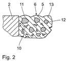
- Figure 1 shows a schematic partial section through an arrangement for Implementation of a preferred variant of the method according to the invention with an implant 1, in the base body 2 of which a recess 4 is provided.
- this recess 4 was a solidifiable, pourable Material mixture filled in the form of granules 5.
- the implant is a stent 1 with a tubular one Base body 2. It is understood, however, that the invention is also related can be used with any other implants. It goes without saying that any materials for the base body are used of the implant can be used. It is only necessary that then the flowable or pourable material or material mixture is matched to this.
- the solidified granulate 5 forms a marker element in the form of an X-ray marker 6.
- the granulate 5 is solidified in one process, which is an endothermic Step includes.
- the endothermic step the granulate 5 so much energy is supplied that there is a sintering of the granules 5 is coming.
- the granules of the granules 5 melt on their surface and merge with each other in the areas where they lie against each other.
- the material cools again and then forms on the basis of the resulting connections between the granules of the granules 5 a solid, which is then the X-ray marker 6 forms. This state is shown in Figure 2.
- a laser 7 is provided with which the granulate 5 is irradiated in a targeted manner in order to to introduce the process energy for the endothermic step into the granulate 5.
- the laser radiates onto the granulate 5 along its beam axis 8.
- the laser 7 can be moved in the direction of the double arrow 9 to the supply sufficient process energy to the entire granulate 5. Doing so the amount of radiation energy introduced in the edge region of the recess 3 regulated so that it is at the interface 10 between the granules 5 and the base body 2 in addition to melting the material of the base body 2 comes.
- the grains 11 of the granules 5 fuse thus superficially with the base body 2, so that there is a kind of welded connection between the X-ray marker 6 and the base body 2.
- the granules 5 consist of a material mixture X-ray-impermeable particles 12, which are covered by a layer 13 consists of material that can be melted by the laser radiation. It understands however, that in other preferred variants instead of a material mixture also at least superficially meltable powder or Granules from a single, then appropriately opaque to radiation Material can be used.
- the method for attaching the X-ray marker 6 is as follows. Around the filling of the granules 5 in the recess 3 will allow Recess 3 open on both sides on its underside with a closure element 14 closed. In the recess 3 in the base body 2 the implant 1 is then filled with such a large amount of the granulate 5, that the recess 3 is almost completely filled. Then follows the endothermic step in which the granulate 5 and the edge region of the base body delimiting the recess 3 2 energy is supplied in the manner described above. Subsequently cools the sintered granulate 5 again and forms the solid with it X-ray marker 6 connected to base body 2.
- FIG. 3 shows an alternative arrangement for carrying out a variant of the inventive method.
- the basic sequence is the same of the one that has been described for FIGS. 1 and 2, so here only the differences should be dealt with.
- One difference is the introduction of process energy into the endothermic one Step of the procedure.
- this is done using a electrical direct current introduced by means of contacts 15 and 16, which Contact the electrically conductive base body 2 'of the implant 1'.
- the Contacts 15 and 16 are arranged so that the electrical direct current flows through the granules 5 '.
- the electrical resistance of the granulate 5 ' that in the example shown from grains of a single radiopaque Material is so large that it essentially due to the flow of electricity heating occurs in the entire granulate bed, a sintering of the granules of the granules 5 'in the 1 and 2 described Way.
- Edge areas 10 'of the base body 2' have a particularly high have electrical resistance to a particular in this area to achieve great local warming, which in turn leads to one of the figures 1 and 2 described local fusing of the granules 5 'with the base body 2' leads.
- the high resistance was thereby oxidation of these edge regions 10 'is achieved.
- a additional shaped element 17 is provided. This is in addition to the closure element 14 'in the area of the upper opening of the recess 3' in Base body 2 'of the implant 1' arranged.
- the closure element 14 ' and the shaped element 17 are designed and the filling quantity of the Granulate 5 'is selected so that there are undercuts between the Base body 2 'and the X-ray marker 6' result. In other words the result is an X-ray marker 6 ', which is the edge region of the recess 3 'embraces.
- a stamp like this can be used is indicated by the dashed contour 18, be provided along the arrow 19 is movable.
- the granulate 5 ' be pressurized during sintering to achieve the sintering result improve.
- closure element, the shaped element and / or the stamp can be formed individually or in combination as heating elements, to provide the process energy for the endothermic step.
- closure element 14 'in the shown Example correspondingly smaller dimensions than the interior of the Has stents so that it is radial after completion of the X-ray marker 6 ' removed from this and can be guided axially out of the stent.
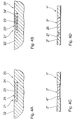
- FIG. 4A shows a variant of an implant 20 according to the invention a recess 21 in the form of a hollow in a base body 22.
- the recess 21 is filled with a flowable suspension of radiopaque Pour particles 23 in a hardening plastic 24, which forms the X-ray marker 25 in the degenerate state.
- FIG. 4B shows a further variant of an implant 20 'according to the invention with a recess 21 'in the form of a hollow in a base body 22 '.
- the recess 21 ' is made of a flowable, hardening plastic 24 'potted, in which in turn an X-ray-opaque element 23' is embedded.
- the element 23 ' forms together with the hardened Plastic bed 24 'the X-ray marker 25'.
- FIG. 4C shows a further variant of a stent 1 "according to the invention.
- the difference to the stent shown in FIG. 1 is that that the recess 3 "in the base body 2" in an immersion process a viscous suspension was filled, as in principle to figure 4A.
- the connection between the resulting X-ray marker 6 "and the base body 2" results from adhesion of the material of the X-ray marker 6 "on the base body 2".
- FIG. 4D shows a further variant of the stent 1 ′′ according to the invention an X-ray marker 26.
- the stent consists in that the 3 "delimiting the recess Area of the base body 2 "one or more undercuts 27 are provided are a positive connection between the Ensure body 2 "and the X-ray marker 26.
- Another difference is that it is the one for the X-ray marker 26 used material to make known from dentistry, cold curing amalgam, which has excellent X-ray opacity having. The material was in its pasty, not hardened Condition brought into the recess 3 "and could then harden there.
- FIG. 5 shows a schematic partial section through a further preferred Execution of the implant according to the invention in the form of a stent 1 "'with a base body 2 "'in which there is a recess 3"'.
- Recess 3 "' was made by galvanic elimination of an X-ray opaque Materials, in the present case gold, an X-ray marker 28 is introduced and solidified.
- the stent 1 '' is shown in a state in FIG which the galvanic separation has just been completed.
- the stent 1 "' is galvanically Solution introduced in the then known manner a galvanic deposition process expires.
- the base body 2 "'of the stent 1"' forms a part of the deposition electrode on which the material of the X-ray marker is attached 28 attaches.
- the recess 3 "'in filled in the manner shown is another part of the deposition electrode of a thin, conductive coating 29 on the in Inside the stent 1 "'arranged closure element 14"' formed which the edge area of the base body 2 "'delimiting the recess 3"' contacted.
- an easily removable Provide protective coating 30, which prevents such accumulation can be, for example, a wax or fat layer or act like that.
- part of the deposition electrode forming, electrically conductive coating in other variants of the invention when removing the closure element also from the X-ray marker can solve, so that the X-ray marker then only from the galvanic deposited material - if necessary with the described deposits etc. - exists.
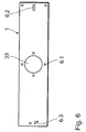
- FIG. 6 shows a schematic top view of the stent 1 from the figures 1 and 2. This is a so-called bifurcation stent, which is used in the area of vascular branches. For this it has a lateral opening 33, which is identified by X-ray markers 6.1 is.
- the stent has 1 further X-ray markers 6.2 and 6.3 on. On the one hand, these serve to mark the ends of the stent 1. On the other hand, their shape and the number of X-ray markers 6.2 or 6.3 chosen so that it provides the surgeon with different information regarding deliver the stent. So give shape and number of X-ray markers 6.2 Information about the date of manufacture of the stent 1, during form and Number of x-ray markers 6.3 represent a product identifier for the stent. It is understood that any other information regarding of the stent is represented by the shape, number and arrangement of the X-ray markers can be.
- the marker elements according to the invention not only in specially provided recesses in the stent wall can be introduced. Likewise, you can advantageously recesses provided by the network structure of the stent wall become. Here they can be distributed over the stent as desired.
Landscapes
- Health & Medical Sciences (AREA)
- Life Sciences & Earth Sciences (AREA)
- Engineering & Computer Science (AREA)
- Biomedical Technology (AREA)
- Animal Behavior & Ethology (AREA)
- Veterinary Medicine (AREA)
- Oral & Maxillofacial Surgery (AREA)
- Public Health (AREA)
- Surgery (AREA)
- Heart & Thoracic Surgery (AREA)
- General Health & Medical Sciences (AREA)
- Molecular Biology (AREA)
- Medical Informatics (AREA)
- Pathology (AREA)
- Nuclear Medicine, Radiotherapy & Molecular Imaging (AREA)
- Cardiology (AREA)
- Transplantation (AREA)
- Vascular Medicine (AREA)
- Prostheses (AREA)
- Media Introduction/Drainage Providing Device (AREA)
Abstract
Description
- Figur 1
- einen schematischen Teilschnitt durch eine Anordnung zur Durchführung einer bevorzugten Variante des erfindungsgemäßen Verfahrens;
- Figur 2
- eine schematische Schnittansicht des Details II aus Figur 1;
- Figur 3
- einen schematischen Teilschnitt durch eine Anordnung zur Durchführung einer weiteren bevorzugten Variante des erfindungsgemäßen Verfahrens;
- Figur 4A bis 4D
- schematische Teilschnitte durch bevorzugte Ausführungen des erfindungsgemäßen Implantats;
- Figur 5
- einen schematischen Teilschnitt durch eine weitere bevorzugte Ausführung des erfindungsgemäßen Implantats;
- Figur 6
- eine schematische Draufsicht auf eine bevorzugte Ausführung eines erfindungsgemäßen Stents.
Claims (15)
- Verfahren zum Anbringen eines Markerelements (6; 6'; 6"; 25; 25'; 26; 28) an einem zum Implantieren in den menschlichen oder tierischen Körper vorgesehenen Implantat (1; 1'; 1"; 1"'; 20; 20'), insbesondere einem Stent, mit einem Grundkörper und einer in diesem Grundkörper (2; 2'; 2"; 2"'; 22; 22') vorgesehenen Ausnehmung (3; 3'; 3"; 3"'; 21; 21') zur Aufnahme des Markerelements (6; 6'; 6"; 25; 25'; 26; 28), dadurch gekennzeichnet, dass zur Ausbildung wenigstens eines Teils des Markerelements (6; 6'; 6"; 25; 25'; 26; 28) ein verfestigbares Material oder Materialgemisch in die Ausnehmung eingebracht und dort verfestigt wird.
- Verfahren nach Anspruch 1, dadurch gekennzeichnet, dass zur Ausbildung wenigstens eines Teils des Markerelements (6; 6'; 6"; 25; 25') ein verfestigbares, fließ- oder schüttfähiges Material oder Materialgemisch in die Ausnehmung eingebracht und dort verfestigt wird.
- Verfahren nach Anspruch 2, dadurch gekennzeichnet, dass das fließoder schüttfähige Material oder Materialgemisch ein sinterfähiges Granulat oder Pulver ist, das in der Ausnehmung durch Sintern verfestigt wird.
- Verfahren nach Anspruch 2 oder 3, dadurch gekennzeichnet, dass das fließ- oder schüttfähige Material oder Materialgemisch während des Verfestigungsvorgangs mit dem Material des Grundkörpers (2; 2'; 2"; 22; 22') verbunden, insbesondere verschweißt wird.
- Verfahren nach einem der vorhergehenden Ansprüche, dadurch gekennzeichnet, dass der Verfestigungsvorgang einen endothermen Schritt umfasst und zumindest ein Teil der Prozessenergie in dem endothermen Schritt lokal im Bereich der Ausnehmung eingebracht wird.
- Verfahren nach Anspruch 5, dadurch gekennzeichnet, dass zumindest ein Teil der Prozessenergie in dem endothermen Schritt durch gezielte Bestrahlung im Bereich der Ausnehmung, insbesondere mit Laserstrahlung, eingebracht wird.
- Verfahren nach Anspruch 5 oder 6, dadurch gekennzeichnet, dass zumindest ein Teil der Prozessenergie in den endothermen Schritt durch Ultraschall eingebracht wird.
- Verfahren nach einem der vorhergehenden Ansprüche, dadurch gekennzeichnet, dass der Verfestigungsvorgang einen endothermen Schritt umfasst und zumindest ein Teil der Prozessenergie in dem endothermen Schritt elektrisch durch Erzeugung eines Stromflusses durch das im Bereich der Ausnehmung (3; 3'; 3"; 21; 21') angeordnete fließ- oder schüttfähige Material oder Materialgemisch eingebracht wird.
- Verfahren nach Anspruch 1, dadurch gekennzeichnet, dass das Einbringen und Verfestigen des Materials oder Materialgemisches durch galvanische Abscheidung erfolgt.
- Verfahren nach Anspruch 1, dadurch gekennzeichnet, dass ein kalt aushärtendes Material oder Materialgemisch, insbesondere Amalgam verwendet wird.
- Implantat, insbesondere Stent, zum Implantieren in den menschlichen oder tierischen Körper mit einem Grundkörper (2; 2'; 2"; 2"'; 22; 22'), wenigstens einer Ausnehmung (3; 3'; 3"; 3"'; 21; 21') in diesem Grundkörper (2; 2'; 2"; 2"'; 22; 22') und einem in dieser Ausnehmung (3; 3'; 3"; 3"'; 21; 21') angeordneten Markerelemente (6; 6'; 6"; 25; 25'; 26; 28), dadurch gekennzeichnet, dass das Markerelemente (6; 6'; 6"; 25; 25'; 26; 28) zumindest teilweise aus einem verfestigbares Material oder Materialgemisch besteht, welches in die Ausnehmung (3; 3'; 3"; 3"'; 21; 21') eingebracht und dort verfestigt ist.
- Implantat nach Anspruch 11, dadurch gekennzeichnet, dass das Markerelemente (6; 6'; 6"; 25; 25') zumindest teilweise aus einem fließ- oder schüttfähige Material oder Materialgemisch besteht, welches in die Ausnehmung (3; 3'; 3"; 21; 21') eingebracht und dort verfestigt ist, oder aus einem Material oder Materialgemisch besteht, welches durch galvanische Abscheidung in die Ausnehmung eingebracht und dort verfestigt ist.
- Implantat nach Anspruch 12, dadurch gekennzeichnet, dass das fließ- oder schüttfähige Material oder Materialgemisch sinterfähig ist und in der Ausnehmung (3; 3'; 3"; 21; 21') durch Sintern verfestigt ist.
- Implantat nach einem der Ansprüche 11 bis 13, dadurch gekennzeichnet, dass das Markerelement (6; 6'; 6"; 25; 25') durch den Verfestigungsvorgang mit dem Material des Grundkörpers (2; 2'; 2"; 22; 22') verbunden, insbesondere verschweißt ist.
- Implantat nach einem der Ansprüche 11 bis 14, dadurch gekennzeichnet, dass die Ausnehmung (3; 3'; 3"; 21; 21') und/oder das Markerelement (6; 6'; 6"; 25; 25') und/oder deren Anordnung bezüglich des Grundkörpers (2; 2'; 2"; 22; 22') zur Kennzeichnung wenigstens einer Eigenschaft des Implantats ausgebildet sind.
Applications Claiming Priority (2)
| Application Number | Priority Date | Filing Date | Title |
|---|---|---|---|
| DE10064596 | 2000-12-18 | ||
| DE10064596A DE10064596A1 (de) | 2000-12-18 | 2000-12-18 | Verfahren zum Anbringen eines Markerelements an einem Implantat sowie mit einem Markerelement versehenes Implantat |
Publications (2)
| Publication Number | Publication Date |
|---|---|
| EP1216665A1 true EP1216665A1 (de) | 2002-06-26 |
| EP1216665B1 EP1216665B1 (de) | 2008-02-06 |
Family
ID=7668684
Family Applications (1)
| Application Number | Title | Priority Date | Filing Date |
|---|---|---|---|
| EP01250443A Expired - Lifetime EP1216665B1 (de) | 2000-12-18 | 2001-12-17 | Verfahren zum Anbringen eines Markerelements an einem Implantat |
Country Status (3)
| Country | Link |
|---|---|
| US (1) | US6899914B2 (de) |
| EP (1) | EP1216665B1 (de) |
| DE (2) | DE10064596A1 (de) |
Families Citing this family (94)
| Publication number | Priority date | Publication date | Assignee | Title |
|---|---|---|---|---|
| US7713297B2 (en) | 1998-04-11 | 2010-05-11 | Boston Scientific Scimed, Inc. | Drug-releasing stent with ceramic-containing layer |
| AU2002345328A1 (en) | 2001-06-27 | 2003-03-03 | Remon Medical Technologies Ltd. | Method and device for electrochemical formation of therapeutic species in vivo |
| DE10201151B4 (de) * | 2002-01-15 | 2007-10-04 | Qualimed Innovative Medizinprodukte Gmbh | Stent mit Marker |
| US8088158B2 (en) * | 2002-12-20 | 2012-01-03 | Boston Scientific Scimed, Inc. | Radiopaque ePTFE medical devices |
| DE10317241A1 (de) | 2003-04-10 | 2004-10-28 | Biotronik Meß- und Therapiegeräte GmbH & Co. Ingenieurbüro Berlin | Stent |
| US20050003103A1 (en) * | 2003-04-29 | 2005-01-06 | Krupa Robert J. | Method for embedding a marking substance in a device such as an insertion tube |
| US8021418B2 (en) * | 2003-06-19 | 2011-09-20 | Boston Scientific Scimed, Inc. | Sandwiched radiopaque marker on covered stent |
| FR2867059B1 (fr) * | 2004-03-03 | 2006-05-26 | Braun Medical | Endoprothese a marqueurs pour conduit d'un corps vivant |
| US9468704B2 (en) | 2004-09-07 | 2016-10-18 | Biotronik Vi Patent Ag | Implant made of a biodegradable magnesium alloy |
| DE102004054084B4 (de) * | 2004-11-09 | 2007-08-02 | Admedes Schuessler Gmbh | Stent mit einem Marker zur Verbesserung der Röntgensichtbarkeit, die Verwendung sowie ein Verfahren zum Herstellen eines derartigen Stents |
| DE102005013547B4 (de) | 2005-03-23 | 2009-02-05 | Admedes Schuessler Gmbh | Aneurysmen-Stent und Verfahren zu seiner Herstellung |
| DE102005019612B4 (de) | 2005-04-27 | 2010-11-25 | Admedes Schuessler Gmbh | Mechanische Verriegelung eines Röntgenmarkers im Eyelet eines Stents oder in einem anderen Körperimplantat |
| DE102005039136B4 (de) | 2005-08-18 | 2011-07-28 | Admedes Schuessler GmbH, 75179 | Verbesserung der Röntgensichtbarkeit und Korrosionsbeständigkeit von NiTi Stents unter Einsatz von Nieten aus Sandwichmaterial |
| US20070156230A1 (en) | 2006-01-04 | 2007-07-05 | Dugan Stephen R | Stents with radiopaque markers |
| US8840660B2 (en) | 2006-01-05 | 2014-09-23 | Boston Scientific Scimed, Inc. | Bioerodible endoprostheses and methods of making the same |
| US8089029B2 (en) | 2006-02-01 | 2012-01-03 | Boston Scientific Scimed, Inc. | Bioabsorbable metal medical device and method of manufacture |
| US20070224235A1 (en) | 2006-03-24 | 2007-09-27 | Barron Tenney | Medical devices having nanoporous coatings for controlled therapeutic agent delivery |
| US8187620B2 (en) | 2006-03-27 | 2012-05-29 | Boston Scientific Scimed, Inc. | Medical devices comprising a porous metal oxide or metal material and a polymer coating for delivering therapeutic agents |
| US8048150B2 (en) | 2006-04-12 | 2011-11-01 | Boston Scientific Scimed, Inc. | Endoprosthesis having a fiber meshwork disposed thereon |
| US20130331926A1 (en) | 2006-05-26 | 2013-12-12 | Abbott Cardiovascular Systems Inc. | Stents With Radiopaque Markers |
| US8815275B2 (en) | 2006-06-28 | 2014-08-26 | Boston Scientific Scimed, Inc. | Coatings for medical devices comprising a therapeutic agent and a metallic material |
| US8771343B2 (en) | 2006-06-29 | 2014-07-08 | Boston Scientific Scimed, Inc. | Medical devices with selective titanium oxide coatings |
| EP2054537A2 (de) | 2006-08-02 | 2009-05-06 | Boston Scientific Scimed, Inc. | Endoprothese mit dreidimensionaler desintegrationssteuerung |
| DE102006038232A1 (de) * | 2006-08-07 | 2008-02-14 | Biotronik Vi Patent Ag | Endoprothese und Verfahren zur Herstellung einer solchen |
| ATE508708T1 (de) | 2006-09-14 | 2011-05-15 | Boston Scient Ltd | Medizinprodukte mit wirkstofffreisetzender beschichtung |
| EP2959925B1 (de) | 2006-09-15 | 2018-08-29 | Boston Scientific Limited | Medizinische vorrichtungen und verfahren zu ihrer herstellung |
| EP2121068B1 (de) | 2006-09-15 | 2010-12-08 | Boston Scientific Scimed, Inc. | Biologisch erodierbare endoprothese mit biostabilen anorganischen schichten |
| JP2010503494A (ja) | 2006-09-15 | 2010-02-04 | ボストン サイエンティフィック リミテッド | 生分解性内部人工器官およびその製造方法 |
| CA2663250A1 (en) | 2006-09-15 | 2008-03-20 | Boston Scientific Limited | Bioerodible endoprostheses and methods of making the same |
| US8002821B2 (en) | 2006-09-18 | 2011-08-23 | Boston Scientific Scimed, Inc. | Bioerodible metallic ENDOPROSTHESES |
| US7981150B2 (en) | 2006-11-09 | 2011-07-19 | Boston Scientific Scimed, Inc. | Endoprosthesis with coatings |
| CA2674195A1 (en) | 2006-12-28 | 2008-07-10 | Boston Scientific Limited | Bioerodible endoprostheses and methods of making same |
| US8431149B2 (en) | 2007-03-01 | 2013-04-30 | Boston Scientific Scimed, Inc. | Coated medical devices for abluminal drug delivery |
| US8070797B2 (en) | 2007-03-01 | 2011-12-06 | Boston Scientific Scimed, Inc. | Medical device with a porous surface for delivery of a therapeutic agent |
| US8545548B2 (en) * | 2007-03-30 | 2013-10-01 | DePuy Synthes Products, LLC | Radiopaque markers for implantable stents and methods for manufacturing the same |
| US8067054B2 (en) | 2007-04-05 | 2011-11-29 | Boston Scientific Scimed, Inc. | Stents with ceramic drug reservoir layer and methods of making and using the same |
| US7976915B2 (en) | 2007-05-23 | 2011-07-12 | Boston Scientific Scimed, Inc. | Endoprosthesis with select ceramic morphology |
| US8002823B2 (en) | 2007-07-11 | 2011-08-23 | Boston Scientific Scimed, Inc. | Endoprosthesis coating |
| US7942926B2 (en) | 2007-07-11 | 2011-05-17 | Boston Scientific Scimed, Inc. | Endoprosthesis coating |
| JP2010533563A (ja) | 2007-07-19 | 2010-10-28 | ボストン サイエンティフィック リミテッド | 吸着抑制表面を有する内部人工器官 |
| US8815273B2 (en) | 2007-07-27 | 2014-08-26 | Boston Scientific Scimed, Inc. | Drug eluting medical devices having porous layers |
| US7931683B2 (en) | 2007-07-27 | 2011-04-26 | Boston Scientific Scimed, Inc. | Articles having ceramic coated surfaces |
| US8221822B2 (en) | 2007-07-31 | 2012-07-17 | Boston Scientific Scimed, Inc. | Medical device coating by laser cladding |
| JP2010535541A (ja) | 2007-08-03 | 2010-11-25 | ボストン サイエンティフィック リミテッド | 広い表面積を有する医療器具用のコーティング |
| US8052745B2 (en) | 2007-09-13 | 2011-11-08 | Boston Scientific Scimed, Inc. | Endoprosthesis |
| US20090076591A1 (en) * | 2007-09-19 | 2009-03-19 | Boston Scientific Scimed, Inc. | Stent Design Allowing Extended Release of Drug and/or Enhanced Adhesion of Polymer to OD Surface |
| US7938855B2 (en) | 2007-11-02 | 2011-05-10 | Boston Scientific Scimed, Inc. | Deformable underlayer for stent |
| US8216632B2 (en) | 2007-11-02 | 2012-07-10 | Boston Scientific Scimed, Inc. | Endoprosthesis coating |
| US8029554B2 (en) | 2007-11-02 | 2011-10-04 | Boston Scientific Scimed, Inc. | Stent with embedded material |
| US7833266B2 (en) | 2007-11-28 | 2010-11-16 | Boston Scientific Scimed, Inc. | Bifurcated stent with drug wells for specific ostial, carina, and side branch treatment |
| US10166127B2 (en) | 2007-12-12 | 2019-01-01 | Intact Vascular, Inc. | Endoluminal device and method |
| US8128677B2 (en) | 2007-12-12 | 2012-03-06 | Intact Vascular LLC | Device and method for tacking plaque to a blood vessel wall |
| US10022250B2 (en) | 2007-12-12 | 2018-07-17 | Intact Vascular, Inc. | Deployment device for placement of multiple intraluminal surgical staples |
| US7896911B2 (en) | 2007-12-12 | 2011-03-01 | Innovasc Llc | Device and method for tacking plaque to blood vessel wall |
| EP2249893A2 (de) * | 2008-02-01 | 2010-11-17 | Boston Scientific Scimed, Inc. | Arzneibeschichtete medizinische vorrichtungen für die differential-arzneifreisetzung |
| EP2271380B1 (de) | 2008-04-22 | 2013-03-20 | Boston Scientific Scimed, Inc. | Medizinprodukte mit einer beschichtung aus anorganischem material |
| WO2009132176A2 (en) | 2008-04-24 | 2009-10-29 | Boston Scientific Scimed, Inc. | Medical devices having inorganic particle layers |
| US7998192B2 (en) | 2008-05-09 | 2011-08-16 | Boston Scientific Scimed, Inc. | Endoprostheses |
| US8236046B2 (en) | 2008-06-10 | 2012-08-07 | Boston Scientific Scimed, Inc. | Bioerodible endoprosthesis |
| US8449603B2 (en) | 2008-06-18 | 2013-05-28 | Boston Scientific Scimed, Inc. | Endoprosthesis coating |
| US7951193B2 (en) | 2008-07-23 | 2011-05-31 | Boston Scientific Scimed, Inc. | Drug-eluting stent |
| US7985252B2 (en) | 2008-07-30 | 2011-07-26 | Boston Scientific Scimed, Inc. | Bioerodible endoprosthesis |
| DE602008006079D1 (de) | 2008-09-30 | 2011-05-19 | Biotronik Vi Patent Ag | Implantat aus einer biologisch abbaubaren Magnesiumlegierung |
| US8382824B2 (en) | 2008-10-03 | 2013-02-26 | Boston Scientific Scimed, Inc. | Medical implant having NANO-crystal grains with barrier layers of metal nitrides or fluorides |
| US8231980B2 (en) | 2008-12-03 | 2012-07-31 | Boston Scientific Scimed, Inc. | Medical implants including iridium oxide |
| US8267992B2 (en) | 2009-03-02 | 2012-09-18 | Boston Scientific Scimed, Inc. | Self-buffering medical implants |
| US8071156B2 (en) | 2009-03-04 | 2011-12-06 | Boston Scientific Scimed, Inc. | Endoprostheses |
| US8287937B2 (en) | 2009-04-24 | 2012-10-16 | Boston Scientific Scimed, Inc. | Endoprosthese |
| US8808353B2 (en) | 2010-01-30 | 2014-08-19 | Abbott Cardiovascular Systems Inc. | Crush recoverable polymer scaffolds having a low crossing profile |
| US8568471B2 (en) | 2010-01-30 | 2013-10-29 | Abbott Cardiovascular Systems Inc. | Crush recoverable polymer scaffolds |
| WO2011119573A1 (en) | 2010-03-23 | 2011-09-29 | Boston Scientific Scimed, Inc. | Surface treated bioerodible metal endoprostheses |
| GB201108185D0 (en) * | 2011-05-17 | 2011-06-29 | Depuy Spine Sarl | Medical implant, method for manufacturing a medical implant and curable mixture |
| US10271973B2 (en) | 2011-06-03 | 2019-04-30 | Intact Vascular, Inc. | Endovascular implant |
| US8726483B2 (en) | 2011-07-29 | 2014-05-20 | Abbott Cardiovascular Systems Inc. | Methods for uniform crimping and deployment of a polymer scaffold |
| WO2014011797A1 (en) * | 2012-07-11 | 2014-01-16 | Intact Vascular, Inc. | Systems and methods for attaching radiopaque markers to a medical device |
| US10561509B2 (en) | 2013-03-13 | 2020-02-18 | DePuy Synthes Products, Inc. | Braided stent with expansion ring and method of delivery |
| CN105188617B (zh) * | 2013-05-07 | 2017-03-08 | 株式会社钟化 | 支架、其制造方法及制造装置 |
| US10206796B2 (en) | 2014-08-27 | 2019-02-19 | DePuy Synthes Products, Inc. | Multi-strand implant with enhanced radiopacity |
| US9375336B1 (en) | 2015-01-29 | 2016-06-28 | Intact Vascular, Inc. | Delivery device and method of delivery |
| US9433520B2 (en) | 2015-01-29 | 2016-09-06 | Intact Vascular, Inc. | Delivery device and method of delivery |
| US10993824B2 (en) | 2016-01-01 | 2021-05-04 | Intact Vascular, Inc. | Delivery device and method of delivery |
| DE102016114894A1 (de) * | 2016-08-11 | 2018-02-15 | Cortronik GmbH | Röntgenmarker für absorbierbare metallische Scaffolds mit hoher Röntgensichtbarkeit und integriertem Selbstpassivierungseffekt |
| US10076428B2 (en) | 2016-08-25 | 2018-09-18 | DePuy Synthes Products, Inc. | Expansion ring for a braided stent |
| US10292851B2 (en) | 2016-09-30 | 2019-05-21 | DePuy Synthes Products, Inc. | Self-expanding device delivery apparatus with dual function bump |
| CN108464879B (zh) * | 2017-02-21 | 2020-04-10 | 上海微创医疗器械(集团)有限公司 | 支架 |
| US11660218B2 (en) | 2017-07-26 | 2023-05-30 | Intact Vascular, Inc. | Delivery device and method of delivery |
| AU2019204522A1 (en) | 2018-07-30 | 2020-02-13 | DePuy Synthes Products, Inc. | Systems and methods of manufacturing and using an expansion ring |
| US10278848B1 (en) | 2018-08-06 | 2019-05-07 | DePuy Synthes Products, Inc. | Stent delivery with expansion assisting delivery wire |
| US10456280B1 (en) | 2018-08-06 | 2019-10-29 | DePuy Synthes Products, Inc. | Systems and methods of using a braided implant |
| US11039944B2 (en) | 2018-12-27 | 2021-06-22 | DePuy Synthes Products, Inc. | Braided stent system with one or more expansion rings |
| EP3763338A1 (de) * | 2019-07-11 | 2021-01-13 | Biotronik Ag | Verfahren zum montieren eines röntgenmarkers in einen stent |
| CN115315278B (zh) * | 2020-02-26 | 2023-10-10 | 巴德股份有限公司 | 具有不透射线标志物的支架移植物及其生产方法 |
| EP4232110B1 (de) * | 2020-10-23 | 2024-12-04 | Cortronik GmbH | Automatisiertes verfahren zur effektiven fixierung von röntgenmarkern in gefässimplantaten |
| US11147694B1 (en) | 2021-03-26 | 2021-10-19 | Vesper Medical, Inc. | Medical implants with structural members having barbs for retaining radiopaque markers |
Citations (5)
| Publication number | Priority date | Publication date | Assignee | Title |
|---|---|---|---|---|
| US5632771A (en) | 1993-07-23 | 1997-05-27 | Cook Incorporated | Flexible stent having a pattern formed from a sheet of material |
| WO1997033534A1 (en) | 1996-03-13 | 1997-09-18 | Medtronic, Inc. | Radiopaque stent markers |
| EP0894503A2 (de) * | 1997-08-01 | 1999-02-03 | Schneider (Usa) Inc. | Bioabsorbierbare Markierungen mit röntgendichten Bestandteilen |
| WO1999015108A2 (en) * | 1997-09-24 | 1999-04-01 | Med Institute, Inc. | Radially expandable stent |
| US6022374A (en) | 1997-12-16 | 2000-02-08 | Cardiovasc, Inc. | Expandable stent having radiopaque marker and method |
Family Cites Families (11)
| Publication number | Priority date | Publication date | Assignee | Title |
|---|---|---|---|---|
| DE3522737A1 (de) * | 1985-06-21 | 1987-01-02 | Wolfgang Geppert | Zahnersatz und verfahren zu dessen verwendung |
| DE3833365C2 (de) * | 1987-09-29 | 2000-12-07 | Biotronik Mess & Therapieg | Vorrichtung zum Ermitteln der räumlichen Ausrichtung eines medizinischen Katheters oder einer medizinischen Sonde |
| US6162244A (en) | 1996-03-29 | 2000-12-19 | Willy Ruesch Ag | Layered stent |
| DE19707642A1 (de) * | 1996-03-29 | 1997-10-02 | Ruesch Willy Ag | Stent |
| DE19653720A1 (de) | 1996-12-10 | 1998-06-18 | Biotronik Mess & Therapieg | Stent |
| US5741327A (en) * | 1997-05-06 | 1998-04-21 | Global Therapeutics, Inc. | Surgical stent featuring radiopaque markers |
| DE19731021A1 (de) * | 1997-07-18 | 1999-01-21 | Meyer Joerg | In vivo abbaubares metallisches Implantat |
| DE19749691A1 (de) * | 1997-10-28 | 1999-04-29 | Biotronik Mess & Therapieg | Stent |
| DE19856983A1 (de) * | 1998-06-25 | 1999-12-30 | Biotronik Mess & Therapieg | Implantierbare, bioresorbierbare Gefäßwandstütze, insbesondere Koronarstent |
| DE59913189D1 (de) | 1998-06-25 | 2006-05-04 | Biotronik Ag | Implantierbare, bioresorbierbare Gefässwandstütze, insbesondere Koronarstent |
| US6379381B1 (en) * | 1999-09-03 | 2002-04-30 | Advanced Cardiovascular Systems, Inc. | Porous prosthesis and a method of depositing substances into the pores |
-
2000
- 2000-12-18 DE DE10064596A patent/DE10064596A1/de not_active Withdrawn
-
2001
- 2001-12-13 US US10/021,899 patent/US6899914B2/en not_active Expired - Lifetime
- 2001-12-17 DE DE50113561T patent/DE50113561D1/de not_active Expired - Lifetime
- 2001-12-17 EP EP01250443A patent/EP1216665B1/de not_active Expired - Lifetime
Patent Citations (5)
| Publication number | Priority date | Publication date | Assignee | Title |
|---|---|---|---|---|
| US5632771A (en) | 1993-07-23 | 1997-05-27 | Cook Incorporated | Flexible stent having a pattern formed from a sheet of material |
| WO1997033534A1 (en) | 1996-03-13 | 1997-09-18 | Medtronic, Inc. | Radiopaque stent markers |
| EP0894503A2 (de) * | 1997-08-01 | 1999-02-03 | Schneider (Usa) Inc. | Bioabsorbierbare Markierungen mit röntgendichten Bestandteilen |
| WO1999015108A2 (en) * | 1997-09-24 | 1999-04-01 | Med Institute, Inc. | Radially expandable stent |
| US6022374A (en) | 1997-12-16 | 2000-02-08 | Cardiovasc, Inc. | Expandable stent having radiopaque marker and method |
Also Published As
| Publication number | Publication date |
|---|---|
| EP1216665B1 (de) | 2008-02-06 |
| US6899914B2 (en) | 2005-05-31 |
| DE10064596A1 (de) | 2002-06-20 |
| DE50113561D1 (de) | 2008-03-20 |
| US20020103528A1 (en) | 2002-08-01 |
Similar Documents
| Publication | Publication Date | Title |
|---|---|---|
| EP1216665B1 (de) | Verfahren zum Anbringen eines Markerelements an einem Implantat | |
| DE69625289T2 (de) | Verfahren zur Herstellung eines gegossenen orthopädischen Implantats | |
| EP3145437B1 (de) | Kieferorthopädische apparatur und verfahren zur herstellung einer kieferorthopädischen apparatur | |
| DE69421935T2 (de) | Gegossene oberfläche für das einwachsen von knochengewebe | |
| DE69105734T2 (de) | Poröse befestigungsfläche. | |
| DE69007069T2 (de) | Kniescheibenprothese und Verfahren zu deren Herstellung. | |
| DE60304925T2 (de) | Verfahren zur Herstellung von einem orthopädischen Implantat mit einer porösen Metalloberfläche | |
| DE69728001T2 (de) | Prothese mit veränderbarer Passungs- und Spannungsverteilung | |
| EP0245846B1 (de) | Prothesenteil sowie Verfahren zu seiner Herstellung | |
| DE69225431T2 (de) | Prosthetisches Implantat | |
| EP2945563B1 (de) | Verfahren zur herstellung eines verankerungselements | |
| DE2730004A1 (de) | Verfahren zum herstellen eines werkstueckes mit koerniger oberflaeche, insbesondere chirurgische prothese | |
| EP0502349A1 (de) | Verfahren zur Herstellung eines Implantates mit einer seine Oberfläche zumindest teilweise bedeckenden metallischen offenzelligen Struktur | |
| DE102012007706B4 (de) | Verfahren zum Herstellen eines künstlichen Gebisses | |
| DE102009014184A1 (de) | Implantat zur Fusion von Wirbelsäulensegmenten | |
| DE102004052364A1 (de) | Verfahren zum Herstellen eines dentalen Modells, eines dentalen Modells mit darauf abgeschiedener Keramikschicht, sowie eines Dentalformteils, dentales Modell, sowie Verwendung eines 3D-Druckers und eines Kits | |
| EP3930625B1 (de) | Verfahren zum herstellen eines formkörpers und geschichteter formkörper | |
| DE102015107600B4 (de) | Partikuläres alloplastisches Knochenersatzmaterial und Verfahren zur Herstellung eines frei geformten porösen Körpers | |
| DE69634255T2 (de) | Elemente für gelenkprothese und verfahren zu deren herstellung | |
| DE102010044571A1 (de) | Basisimplantat | |
| DE102016202333B3 (de) | Implantat zur Rekonstruktion einer Hüftgelenkpfanne | |
| EP0898469A1 (de) | Implantat und verfahren zu dessen herstellung | |
| EP3092977B1 (de) | Flächiges knochenersatzmaterial und verfahren zur herstellung eines porösen körpers | |
| DE2129832A1 (de) | Hueftgelenksprothese und Verfahren zu ihrer Herstellung | |
| EP4188284B1 (de) | Implantierbare kiefergelenksprothese und entsprechendes herstellungsverfahren |
Legal Events
| Date | Code | Title | Description |
|---|---|---|---|
| PUAI | Public reference made under article 153(3) epc to a published international application that has entered the european phase |
Free format text: ORIGINAL CODE: 0009012 |
|
| AK | Designated contracting states |
Kind code of ref document: A1 Designated state(s): AT BE CH CY DE DK ES FI FR GB GR IE IT LI LU MC NL PT SE TR |
|
| AX | Request for extension of the european patent |
Free format text: AL;LT;LV;MK;RO;SI |
|
| 17P | Request for examination filed |
Effective date: 20021227 |
|
| AKX | Designation fees paid |
Designated state(s): CH DE FR GB IT LI NL |
|
| RAP1 | Party data changed (applicant data changed or rights of an application transferred) |
Owner name: BIOTRONIK GMBH & CO. KG |
|
| RIC1 | Information provided on ipc code assigned before grant |
Ipc: A61B 19/00 20060101ALI20060911BHEP Ipc: A61F 2/82 20060101AFI20060911BHEP |
|
| GRAP | Despatch of communication of intention to grant a patent |
Free format text: ORIGINAL CODE: EPIDOSNIGR1 |
|
| RIN1 | Information on inventor provided before grant (corrected) |
Inventor name: BEHREND, DETLEF Inventor name: GOBRECHT, JENS Inventor name: SCHALDACH, MAX Inventor name: RZANY, ALEXANDER Inventor name: SCHMITZ, KLAUS-PETER |
|
| GRAS | Grant fee paid |
Free format text: ORIGINAL CODE: EPIDOSNIGR3 |
|
| GRAA | (expected) grant |
Free format text: ORIGINAL CODE: 0009210 |
|
| AK | Designated contracting states |
Kind code of ref document: B1 Designated state(s): CH DE FR GB IT LI NL |
|
| REG | Reference to a national code |
Ref country code: GB Ref legal event code: FG4D Free format text: NOT ENGLISH |
|
| REG | Reference to a national code |
Ref country code: CH Ref legal event code: EP |
|
| REF | Corresponds to: |
Ref document number: 50113561 Country of ref document: DE Date of ref document: 20080320 Kind code of ref document: P |
|
| GBT | Gb: translation of ep patent filed (gb section 77(6)(a)/1977) |
Effective date: 20080305 |
|
| NLV1 | Nl: lapsed or annulled due to failure to fulfill the requirements of art. 29p and 29m of the patents act | ||
| ET | Fr: translation filed | ||
| PG25 | Lapsed in a contracting state [announced via postgrant information from national office to epo] |
Ref country code: NL Free format text: LAPSE BECAUSE OF FAILURE TO SUBMIT A TRANSLATION OF THE DESCRIPTION OR TO PAY THE FEE WITHIN THE PRESCRIBED TIME-LIMIT Effective date: 20080206 |
|
| PLBE | No opposition filed within time limit |
Free format text: ORIGINAL CODE: 0009261 |
|
| STAA | Information on the status of an ep patent application or granted ep patent |
Free format text: STATUS: NO OPPOSITION FILED WITHIN TIME LIMIT |
|
| 26N | No opposition filed |
Effective date: 20081107 |
|
| PG25 | Lapsed in a contracting state [announced via postgrant information from national office to epo] |
Ref country code: IT Free format text: LAPSE BECAUSE OF FAILURE TO SUBMIT A TRANSLATION OF THE DESCRIPTION OR TO PAY THE FEE WITHIN THE PRESCRIBED TIME-LIMIT Effective date: 20080206 |
|
| REG | Reference to a national code |
Ref country code: DE Ref legal event code: R082 Ref document number: 50113561 Country of ref document: DE Representative=s name: RANDOLL, SOEREN, DIPL.-CHEM. UNIV. DR. RER. NA, DE Ref country code: DE Ref legal event code: R082 Ref document number: 50113561 Country of ref document: DE |
|
| REG | Reference to a national code |
Ref country code: DE Ref legal event code: R081 Ref document number: 50113561 Country of ref document: DE Owner name: BIOTRONIK SE & CO. KG, DE Free format text: FORMER OWNER: BIOTRONIK GMBH & CO. KG, 12359 BERLIN, DE Effective date: 20111219 |
|
| REG | Reference to a national code |
Ref country code: FR Ref legal event code: PLFP Year of fee payment: 15 |
|
| REG | Reference to a national code |
Ref country code: FR Ref legal event code: PLFP Year of fee payment: 16 |
|
| REG | Reference to a national code |
Ref country code: FR Ref legal event code: PLFP Year of fee payment: 17 |
|
| REG | Reference to a national code |
Ref country code: FR Ref legal event code: CD Owner name: BIOTRONIK SE & CO. KG, DE Effective date: 20181002 |
|
| PGFP | Annual fee paid to national office [announced via postgrant information from national office to epo] |
Ref country code: CH Payment date: 20201222 Year of fee payment: 20 Ref country code: GB Payment date: 20201222 Year of fee payment: 20 Ref country code: FR Payment date: 20201217 Year of fee payment: 20 |
|
| PGFP | Annual fee paid to national office [announced via postgrant information from national office to epo] |
Ref country code: DE Payment date: 20201218 Year of fee payment: 20 |
|
| REG | Reference to a national code |
Ref country code: DE Ref legal event code: R071 Ref document number: 50113561 Country of ref document: DE |
|
| REG | Reference to a national code |
Ref country code: CH Ref legal event code: PL |
|
| REG | Reference to a national code |
Ref country code: GB Ref legal event code: PE20 Expiry date: 20211216 |
|
| PG25 | Lapsed in a contracting state [announced via postgrant information from national office to epo] |
Ref country code: GB Free format text: LAPSE BECAUSE OF EXPIRATION OF PROTECTION Effective date: 20211216 |