EP1216852A2 - Cord embedded rubber tape for making tyre component, tyre component and tyre - Google Patents
Cord embedded rubber tape for making tyre component, tyre component and tyre Download PDFInfo
- Publication number
- EP1216852A2 EP1216852A2 EP01310576A EP01310576A EP1216852A2 EP 1216852 A2 EP1216852 A2 EP 1216852A2 EP 01310576 A EP01310576 A EP 01310576A EP 01310576 A EP01310576 A EP 01310576A EP 1216852 A2 EP1216852 A2 EP 1216852A2
- Authority
- EP
- European Patent Office
- Prior art keywords
- tape
- tyre
- cord
- rubber
- component
- Prior art date
- Legal status (The legal status is an assumption and is not a legal conclusion. Google has not performed a legal analysis and makes no representation as to the accuracy of the status listed.)
- Granted
Links
Images




Classifications
-
- B—PERFORMING OPERATIONS; TRANSPORTING
- B60—VEHICLES IN GENERAL
- B60C—VEHICLE TYRES; TYRE INFLATION; TYRE CHANGING; CONNECTING VALVES TO INFLATABLE ELASTIC BODIES IN GENERAL; DEVICES OR ARRANGEMENTS RELATED TO TYRES
- B60C11/00—Tyre tread bands; Tread patterns; Anti-skid inserts
- B60C11/14—Anti-skid inserts, e.g. vulcanised into the tread band
-
- B—PERFORMING OPERATIONS; TRANSPORTING
- B29—WORKING OF PLASTICS; WORKING OF SUBSTANCES IN A PLASTIC STATE IN GENERAL
- B29D—PRODUCING PARTICULAR ARTICLES FROM PLASTICS OR FROM SUBSTANCES IN A PLASTIC STATE
- B29D30/00—Producing pneumatic or solid tyres or parts thereof
- B29D30/06—Pneumatic tyres or parts thereof (e.g. produced by casting, moulding, compression moulding, injection moulding, centrifugal casting)
- B29D30/52—Unvulcanised treads, e.g. on used tyres; Retreading
- B29D30/58—Applying bands of rubber treads, i.e. applying camel backs
- B29D30/60—Applying bands of rubber treads, i.e. applying camel backs by winding narrow strips
-
- B—PERFORMING OPERATIONS; TRANSPORTING
- B60—VEHICLES IN GENERAL
- B60C—VEHICLE TYRES; TYRE INFLATION; TYRE CHANGING; CONNECTING VALVES TO INFLATABLE ELASTIC BODIES IN GENERAL; DEVICES OR ARRANGEMENTS RELATED TO TYRES
- B60C11/00—Tyre tread bands; Tread patterns; Anti-skid inserts
- B60C11/0041—Tyre tread bands; Tread patterns; Anti-skid inserts comprising different tread rubber layers
- B60C11/005—Tyre tread bands; Tread patterns; Anti-skid inserts comprising different tread rubber layers with cap and base layers
-
- B—PERFORMING OPERATIONS; TRANSPORTING
- B60—VEHICLES IN GENERAL
- B60C—VEHICLE TYRES; TYRE INFLATION; TYRE CHANGING; CONNECTING VALVES TO INFLATABLE ELASTIC BODIES IN GENERAL; DEVICES OR ARRANGEMENTS RELATED TO TYRES
- B60C9/00—Reinforcements or ply arrangement of pneumatic tyres
-
- B—PERFORMING OPERATIONS; TRANSPORTING
- B60—VEHICLES IN GENERAL
- B60C—VEHICLE TYRES; TYRE INFLATION; TYRE CHANGING; CONNECTING VALVES TO INFLATABLE ELASTIC BODIES IN GENERAL; DEVICES OR ARRANGEMENTS RELATED TO TYRES
- B60C9/00—Reinforcements or ply arrangement of pneumatic tyres
- B60C9/02—Carcasses
- B60C9/04—Carcasses the reinforcing cords of each carcass ply arranged in a substantially parallel relationship
- B60C9/08—Carcasses the reinforcing cords of each carcass ply arranged in a substantially parallel relationship the cords extend transversely from bead to bead, i.e. radial ply
- B60C9/09—Carcasses the reinforcing cords of each carcass ply arranged in a substantially parallel relationship the cords extend transversely from bead to bead, i.e. radial ply combined with other carcass plies having cords extending diagonally from bead to bead, i.e. combined radial ply and bias angle ply
-
- B—PERFORMING OPERATIONS; TRANSPORTING
- B60—VEHICLES IN GENERAL
- B60C—VEHICLE TYRES; TYRE INFLATION; TYRE CHANGING; CONNECTING VALVES TO INFLATABLE ELASTIC BODIES IN GENERAL; DEVICES OR ARRANGEMENTS RELATED TO TYRES
- B60C9/00—Reinforcements or ply arrangement of pneumatic tyres
- B60C9/02—Carcasses
- B60C9/12—Carcasses built-up with rubberised layers of discrete fibres or filaments
-
- B—PERFORMING OPERATIONS; TRANSPORTING
- B60—VEHICLES IN GENERAL
- B60C—VEHICLE TYRES; TYRE INFLATION; TYRE CHANGING; CONNECTING VALVES TO INFLATABLE ELASTIC BODIES IN GENERAL; DEVICES OR ARRANGEMENTS RELATED TO TYRES
- B60C9/00—Reinforcements or ply arrangement of pneumatic tyres
- B60C9/18—Structure or arrangement of belts or breakers, crown-reinforcing or cushioning layers
- B60C9/1821—Structure or arrangement of belts or breakers, crown-reinforcing or cushioning layers comprising discrete fibres or filaments
-
- B—PERFORMING OPERATIONS; TRANSPORTING
- B60—VEHICLES IN GENERAL
- B60C—VEHICLE TYRES; TYRE INFLATION; TYRE CHANGING; CONNECTING VALVES TO INFLATABLE ELASTIC BODIES IN GENERAL; DEVICES OR ARRANGEMENTS RELATED TO TYRES
- B60C9/00—Reinforcements or ply arrangement of pneumatic tyres
- B60C9/18—Structure or arrangement of belts or breakers, crown-reinforcing or cushioning layers
- B60C9/20—Structure or arrangement of belts or breakers, crown-reinforcing or cushioning layers built-up from rubberised plies each having all cords arranged substantially parallel
- B60C9/22—Structure or arrangement of belts or breakers, crown-reinforcing or cushioning layers built-up from rubberised plies each having all cords arranged substantially parallel the plies being arranged with all cords disposed along the circumference of the tyre
- B60C9/2204—Structure or arrangement of belts or breakers, crown-reinforcing or cushioning layers built-up from rubberised plies each having all cords arranged substantially parallel the plies being arranged with all cords disposed along the circumference of the tyre obtained by circumferentially narrow strip winding
-
- B—PERFORMING OPERATIONS; TRANSPORTING
- B29—WORKING OF PLASTICS; WORKING OF SUBSTANCES IN A PLASTIC STATE IN GENERAL
- B29C—SHAPING OR JOINING OF PLASTICS; SHAPING OF MATERIAL IN A PLASTIC STATE, NOT OTHERWISE PROVIDED FOR; AFTER-TREATMENT OF THE SHAPED PRODUCTS, e.g. REPAIRING
- B29C48/00—Extrusion moulding, i.e. expressing the moulding material through a die or nozzle which imparts the desired form; Apparatus therefor
- B29C48/03—Extrusion moulding, i.e. expressing the moulding material through a die or nozzle which imparts the desired form; Apparatus therefor characterised by the shape of the extruded material at extrusion
- B29C48/07—Flat, e.g. panels
-
- B—PERFORMING OPERATIONS; TRANSPORTING
- B29—WORKING OF PLASTICS; WORKING OF SUBSTANCES IN A PLASTIC STATE IN GENERAL
- B29C—SHAPING OR JOINING OF PLASTICS; SHAPING OF MATERIAL IN A PLASTIC STATE, NOT OTHERWISE PROVIDED FOR; AFTER-TREATMENT OF THE SHAPED PRODUCTS, e.g. REPAIRING
- B29C48/00—Extrusion moulding, i.e. expressing the moulding material through a die or nozzle which imparts the desired form; Apparatus therefor
- B29C48/03—Extrusion moulding, i.e. expressing the moulding material through a die or nozzle which imparts the desired form; Apparatus therefor characterised by the shape of the extruded material at extrusion
- B29C48/12—Articles with an irregular circumference when viewed in cross-section, e.g. window profiles
-
- B—PERFORMING OPERATIONS; TRANSPORTING
- B29—WORKING OF PLASTICS; WORKING OF SUBSTANCES IN A PLASTIC STATE IN GENERAL
- B29C—SHAPING OR JOINING OF PLASTICS; SHAPING OF MATERIAL IN A PLASTIC STATE, NOT OTHERWISE PROVIDED FOR; AFTER-TREATMENT OF THE SHAPED PRODUCTS, e.g. REPAIRING
- B29C48/00—Extrusion moulding, i.e. expressing the moulding material through a die or nozzle which imparts the desired form; Apparatus therefor
- B29C48/25—Component parts, details or accessories; Auxiliary operations
- B29C48/30—Extrusion nozzles or dies
- B29C48/32—Extrusion nozzles or dies with annular openings, e.g. for forming tubular articles
- B29C48/33—Extrusion nozzles or dies with annular openings, e.g. for forming tubular articles with parts rotatable relative to each other
-
- B—PERFORMING OPERATIONS; TRANSPORTING
- B29—WORKING OF PLASTICS; WORKING OF SUBSTANCES IN A PLASTIC STATE IN GENERAL
- B29D—PRODUCING PARTICULAR ARTICLES FROM PLASTICS OR FROM SUBSTANCES IN A PLASTIC STATE
- B29D30/00—Producing pneumatic or solid tyres or parts thereof
- B29D30/06—Pneumatic tyres or parts thereof (e.g. produced by casting, moulding, compression moulding, injection moulding, centrifugal casting)
- B29D30/08—Building tyres
- B29D30/10—Building tyres on round cores, i.e. the shape of the core is approximately identical with the shape of the completed tyre
- B29D30/16—Applying the layers; Guiding or stretching the layers during application
- B29D2030/1664—Details, accessories or auxiliary operations not provided for in the other subgroups of B29D30/00
- B29D2030/1678—Details, accessories or auxiliary operations not provided for in the other subgroups of B29D30/00 the layers being applied being substantially continuous, i.e. not being cut before the application step
-
- B—PERFORMING OPERATIONS; TRANSPORTING
- B29—WORKING OF PLASTICS; WORKING OF SUBSTANCES IN A PLASTIC STATE IN GENERAL
- B29D—PRODUCING PARTICULAR ARTICLES FROM PLASTICS OR FROM SUBSTANCES IN A PLASTIC STATE
- B29D30/00—Producing pneumatic or solid tyres or parts thereof
- B29D30/06—Pneumatic tyres or parts thereof (e.g. produced by casting, moulding, compression moulding, injection moulding, centrifugal casting)
- B29D30/08—Building tyres
- B29D30/20—Building tyres by the flat-tyre method, i.e. building on cylindrical drums
- B29D30/30—Applying the layers; Guiding or stretching the layers during application
- B29D2030/3064—Details, accessories and auxiliary operations not otherwise provided for
- B29D2030/3078—Details, accessories and auxiliary operations not otherwise provided for the layers being applied being substantially continuous, i.e. not being cut before the application step
-
- B—PERFORMING OPERATIONS; TRANSPORTING
- B60—VEHICLES IN GENERAL
- B60C—VEHICLE TYRES; TYRE INFLATION; TYRE CHANGING; CONNECTING VALVES TO INFLATABLE ELASTIC BODIES IN GENERAL; DEVICES OR ARRANGEMENTS RELATED TO TYRES
- B60C13/00—Tyre sidewalls; Protecting, decorating, marking, or the like, thereof
- B60C2013/008—Tyre sidewalls; Protecting, decorating, marking, or the like, thereof built-up by narrow strip winding
-
- B—PERFORMING OPERATIONS; TRANSPORTING
- B60—VEHICLES IN GENERAL
- B60C—VEHICLE TYRES; TYRE INFLATION; TYRE CHANGING; CONNECTING VALVES TO INFLATABLE ELASTIC BODIES IN GENERAL; DEVICES OR ARRANGEMENTS RELATED TO TYRES
- B60C13/00—Tyre sidewalls; Protecting, decorating, marking, or the like, thereof
- B60C13/04—Tyre sidewalls; Protecting, decorating, marking, or the like, thereof having annular inlays or covers, e.g. white sidewalls
- B60C2013/045—Tyre sidewalls; Protecting, decorating, marking, or the like, thereof having annular inlays or covers, e.g. white sidewalls comprising different sidewall rubber layers
-
- Y—GENERAL TAGGING OF NEW TECHNOLOGICAL DEVELOPMENTS; GENERAL TAGGING OF CROSS-SECTIONAL TECHNOLOGIES SPANNING OVER SEVERAL SECTIONS OF THE IPC; TECHNICAL SUBJECTS COVERED BY FORMER USPC CROSS-REFERENCE ART COLLECTIONS [XRACs] AND DIGESTS
- Y10—TECHNICAL SUBJECTS COVERED BY FORMER USPC
- Y10T—TECHNICAL SUBJECTS COVERED BY FORMER US CLASSIFICATION
- Y10T152/00—Resilient tires and wheels
- Y10T152/10—Tires, resilient
- Y10T152/10495—Pneumatic tire or inner tube
- Y10T152/10513—Tire reinforcement material characterized by short length fibers or the like
-
- Y—GENERAL TAGGING OF NEW TECHNOLOGICAL DEVELOPMENTS; GENERAL TAGGING OF CROSS-SECTIONAL TECHNOLOGIES SPANNING OVER SEVERAL SECTIONS OF THE IPC; TECHNICAL SUBJECTS COVERED BY FORMER USPC CROSS-REFERENCE ART COLLECTIONS [XRACs] AND DIGESTS
- Y10—TECHNICAL SUBJECTS COVERED BY FORMER USPC
- Y10T—TECHNICAL SUBJECTS COVERED BY FORMER US CLASSIFICATION
- Y10T428/00—Stock material or miscellaneous articles
- Y10T428/24—Structurally defined web or sheet [e.g., overall dimension, etc.]
- Y10T428/24132—Structurally defined web or sheet [e.g., overall dimension, etc.] including grain, strips, or filamentary elements in different layers or components parallel
-
- Y—GENERAL TAGGING OF NEW TECHNOLOGICAL DEVELOPMENTS; GENERAL TAGGING OF CROSS-SECTIONAL TECHNOLOGIES SPANNING OVER SEVERAL SECTIONS OF THE IPC; TECHNICAL SUBJECTS COVERED BY FORMER USPC CROSS-REFERENCE ART COLLECTIONS [XRACs] AND DIGESTS
- Y10—TECHNICAL SUBJECTS COVERED BY FORMER USPC
- Y10T—TECHNICAL SUBJECTS COVERED BY FORMER US CLASSIFICATION
- Y10T428/00—Stock material or miscellaneous articles
- Y10T428/24—Structurally defined web or sheet [e.g., overall dimension, etc.]
- Y10T428/24479—Structurally defined web or sheet [e.g., overall dimension, etc.] including variation in thickness
-
- Y—GENERAL TAGGING OF NEW TECHNOLOGICAL DEVELOPMENTS; GENERAL TAGGING OF CROSS-SECTIONAL TECHNOLOGIES SPANNING OVER SEVERAL SECTIONS OF THE IPC; TECHNICAL SUBJECTS COVERED BY FORMER USPC CROSS-REFERENCE ART COLLECTIONS [XRACs] AND DIGESTS
- Y10—TECHNICAL SUBJECTS COVERED BY FORMER USPC
- Y10T—TECHNICAL SUBJECTS COVERED BY FORMER US CLASSIFICATION
- Y10T428/00—Stock material or miscellaneous articles
- Y10T428/24—Structurally defined web or sheet [e.g., overall dimension, etc.]
- Y10T428/24479—Structurally defined web or sheet [e.g., overall dimension, etc.] including variation in thickness
- Y10T428/24612—Composite web or sheet
-
- Y—GENERAL TAGGING OF NEW TECHNOLOGICAL DEVELOPMENTS; GENERAL TAGGING OF CROSS-SECTIONAL TECHNOLOGIES SPANNING OVER SEVERAL SECTIONS OF THE IPC; TECHNICAL SUBJECTS COVERED BY FORMER USPC CROSS-REFERENCE ART COLLECTIONS [XRACs] AND DIGESTS
- Y10—TECHNICAL SUBJECTS COVERED BY FORMER USPC
- Y10T—TECHNICAL SUBJECTS COVERED BY FORMER US CLASSIFICATION
- Y10T428/00—Stock material or miscellaneous articles
- Y10T428/249921—Web or sheet containing structurally defined element or component
- Y10T428/249924—Noninterengaged fiber-containing paper-free web or sheet which is not of specified porosity
- Y10T428/249933—Fiber embedded in or on the surface of a natural or synthetic rubber matrix
- Y10T428/249934—Fibers are aligned substantially parallel
Definitions
- the present invention relates to a cord-embedded rubber tape wound into a tyre component, a tyre component made of windings of such tape, and a pneumatic tyre comprising such tyre component.
- An object of the present invention is therefore, to provide a tape for making tyre components, in which the above-mentioned drawbacks are removed by embedding a cord in the tape.
- Another object of the present invention is to provide a tyre component which is made by winding the cord-embedded rubber tape.
- Still another object of the present invention is to provide a pneumatic tyre which comprises a tyre component made of windings of the cord-embedded rubber tape.
- a tape which is wound into a tyre component is made of unvulcanised rubber in which at least one cord is embedded along the length thereof, the number of the at least one cord is at most three, and a total width of the at least one cord in the widthwise direction of the tape is in a rage of from 1/100 to 1/2 times the width of the tape.
- the cord or cords prevent elongation of the tape in the longitudinal direction and provide support for the unvulcanised rubber.
- a pneumatic tyre 20 is made up of tyre components 2 which include rubber components 4 and cord-reinforced components 5.
- the tyre 20 comprises a tread portion 22, a pair of sidewall portions 23, a pair of axially spaced bead portions 24 each with a bead core 25 therein, a carcass 26 extending between the bead portions 24, a belt disposed radially outside the carcass in the tread portion.
- the belt includes a breaker 27 and optionally a band 10, outside the breaker 27.
- the carcass 26 comprises a ply of carcass cords arranged radially at an angle in a range of from 70 to 90 degrees with respect to the tyre equator, extending between the bead portions 24 through the tread portion 22 and sidewall portions 23 and turned up around the bead core 25 in each bead portion 24.
- the breaker 27 comprises two cross plies 27A and 27B of parallel cords arranged at an angle of from 10 to 35 degrees with respect to the tyre equator.
- organic fibre cords e.g. nylon, polyester, rayon, and aromatic polyamide and the like, and steel cords may be used.
- the cord-reinforced components 5 include the carcass 26 and breaker 27 at least.
- the rubber components 4 include a radially outer tread rubber G1 and a radially inner tread base rubber G1A which are disposed in the tread portion 22, a sidewall rubber G2 disposed in each of the sidewall portions 23, a chafer rubber G3 disposed in each of the bead portions 24, and a wedge-shaped breaker cushion rubber G4 disposes between each edge of the breaker 27 and the carcass 26.
- the tread base rubber G1A and an axially inner part of the sidewall rubber G2 are each formed by winding a tape 1.
- the tape 1 is made of an unvulcanised rubber 6 in which at least one but at most three cords 7 are embedded along the length thereof.
- the thickness TA of the tape 1 is constant across the overall tape width and larger than the cord thickness T1.
- the thickness TA of the tape 1 is large enough in the position of the cord so as to completely cover the cord. But, the remaining most part has a constant thickness not more than the cord thickness T1.
- the tape 1 is wound around a drum (d) into a predetermined target cross sectional shape K to make a raw tyre component used to make a raw tyre.
- the target cross sectional shape K is such that the edges portions are tapered but the main portion therebetween is substantially constant thickness.
- the thickness TA of the portion other than the cord position is in a range of from 0.5 to 1.5 mm.
- the width WA of the tape 1 may be set in a range of from 10 to 30 mm.
- the important main function of the cord(s) is to reinforce the tape itself to provide dimensional stability in its longitudinal direction and to feed the very thin unvulcanised rubber tape stably with the drum. However, it is also preferable to provide the cord(s) with an additional function to reinforce the tyre component.
- the cord 7 having a rupture strength of more than about 9,000 kgf/sq.cm and a diameter D of from 0.5 to 1.0 mm is used in order to improve tyre performance, tyre weight and tyre production efficiency.
- organic fibre cords e.g. nylon, polyester, rayon, aromatic polyamide, cotton yarn and the like may be used.
- the total width W1 of the cord(s) 7 is set in a range of from 1/100 to 1/2 times the width WA of the tape 1.
- the total width W1 is the product of a cord width Wa and the cord number. (Usually, as the cord has a circular cross sectional shape, the cord width Wa is the same as the above-mentioned thickness T1.)
- an organic fibre cord such as nylon cords is preferably used as the cord 7.
- the winding pitches P are about 1/3 time the width WA of the tape 1.
- the three-layered main portion having a thickness T being about 3 times the thickness TA of the tape 1 is formed.
- the thickness T becomes about 4 times the thickness TA.
- the thickness T is about 2 times the thickness TA.
- a spiral cord structure 10 which functions as a tread band is formed within the tread base rubber G1A at the same time.
- the cross sectional shape and thickness T of the tyre component and the cord pitches CP of the spiral cord structure 10 can be easily controlled by changing the winding pitches P, tape width WA and tape thickness TA.
- the unvulcanised rubber 6 of the tape 1 has short fibres 11 which are dispersed therein which are oriented in the longitudinal direction of the tape.
- organic fibres e.g. nylon, polyester, rayon, vinylon, aromatic polyamide, cotton, cellulose resin, crystalline polybutadiene and the like
- metal fibres or whiskers e.g. boron alloy, glass fibres and the like can be used alone or in combination.
- the steering stability and durability of the tyre may be improved. Further, the inclusion of the short fibres 11 may contribute to increasing of the tape feeding speed and winding speed, and improving of the dimensional accuracy, and further simplifying of the tape conveying mechanism.
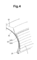
- Fig.4 shows the above-mentioned sidewall base rubber G2A formed by spirally winding a tape 1 on the axially outer surface of the carcass 26 which has been changed from a cylindrical shape to a toroidal shape in a tyre making process.
- the sidewall base rubber G2A in this example is relatively thin in comparison with the tread base rubber G1A.
- a tape 1 whose thickness is almost the same as the sidewall base rubber G2A is wound without overlapping each other and the windings are butt jointed.
- a veneer sidewall rubber G2B which is a wide strip of sidewall rubber compound is applied to the axially outer side of the sidewall base rubber G2A as the axially outermost part of the sidewall rubber G2.
- cord(s) 7 and short fibres 11 are increased to improve the manoeuvrability, high-speed stability and the like, without deteriorating the ride comfort, which may contribute to a tyre weight reduction.
- the above-mentioned rubber tapes 1 can be utilised to make a band 10 disposed on the radially outside of the breaker 27.
- the band 10 is formed by winding a tape 1 at variable cord pitches CP.
- the cord pitches CP1 are smaller than the tape width WA, but in the central portion, the cord pitches CP2 are the substantially same as or slightly smaller than the tape width WA.
- the windings are butt jointed or slightly overlapped. If the tape 1 is wound leaving spaces between the windings, air is liable to be trapped therein, and further the hooping force becomes uneven in the axial direction.
- Figs.6 and 7 each show an apparatus for making the tape 1.
- the apparatus comprises a screw type rubber extruder 30, a pair of calender rollers 32 disposed near the head of the extruder 30, a cord reel 33 disposed on the back side of the extruder 30, and a pull roller 33 for the tape disposed on the downstream side of the calender roller 32.
- the cord 7 supplied from the cord reel 33 is drawn out through the main part 31 of the extruder 30, a through hole extending along a screw axis 31A, the head and a die 31B and a gap between the calender roller 32.
- the unvulcanised rubber 6 is extruded and rolled into the tape having the predetermined thickness TA and width WA.
- the apparatus comprises a rubber extruder 30, a pair of calender rollers 32 disposed near the head of the extruder 30, a cord reel 33, a guide roller 34 for the cord 7, and a pull roller 33 for the tape on the downstream side of the calender roller 32.
- the cord 7 is drawn out through the calender rollers 32 without passing through the inside of the extruder 30, and at the same time, the unvulcanised rubber 6 is extruded and rolled into the tape. In this case, it will be easier than the former example to embed a plurality of cords in the extruded unvulcanised rubber.
- the unvulcanised rubber tape according to the present invention has at least one cord embedded therein. Therefore, the dimensional stability and strength of the tape, especially in the longitudinal direction is greatly improved, and the handling properties are improved. As a result, the tape conveying or feeding speed and winding speed can be increased. Further, it becomes possible to promote simplifying of the tape conveying mechanism.
- tyre components such as the tread base rubber, sidewall base rubber and tread band are made of windings of the tape. Accordingly, the tyre components themselves are reinforced by the cord(s) in the tape, which makes it unnecessary to provide additional reinforcing cord layers or makes it possible to lessen such layers. Also, it is possible to improve the tyre weight and tyre performance. In the present invention, therefore, the facilities cost and production cost can be effectively reduced.
Landscapes
- Engineering & Computer Science (AREA)
- Mechanical Engineering (AREA)
- Tires In General (AREA)
- Tyre Moulding (AREA)
- Reinforced Plastic Materials (AREA)
Abstract
Description
Claims (5)
- A tape to be wound into a tyre component which is made of unvulcanised rubber, characterised in that at least one cord (7) is embedded along the length of the cords, the number of said at least one cord (7) being at most three, and a total width (W1) of said at least one cord (7) in the widthwise direction of the tape being in a rage of from 1/100 to 1/2 times the width (WA1) of the tape.
- A tape according to claim 1, characterised in that said at least one cord (7) has a diameter D in a range of 0.3 to 1.5 mm, said width (WA)of the tape is in a range of from 10 to 30 mm, and the thickness (T) of the tape is in range of from 0.5 to 1.5 mm when measured in a portion other than the cord position.
- A tape according to claim 1 or 2, characterised in that the unvulcanised rubber has short fibres therein, and the short fibres are oriented in the longitudinal direction of the tape.
- A tyre component characterised in that it is made of windings of a tape as claimed in claim 1, 2 or 3.
- A pneumatic tyre characterised by a tyre component made of windings of a tape as claimed in claim 1, 2 or 3.
Applications Claiming Priority (2)
| Application Number | Priority Date | Filing Date | Title |
|---|---|---|---|
| JP2000387780 | 2000-12-20 | ||
| JP2000387780A JP3706540B2 (en) | 2000-12-20 | 2000-12-20 | Rubber strip, strip tire component formed using the same, and pneumatic tire using the same |
Publications (3)
| Publication Number | Publication Date |
|---|---|
| EP1216852A2 true EP1216852A2 (en) | 2002-06-26 |
| EP1216852A3 EP1216852A3 (en) | 2003-06-18 |
| EP1216852B1 EP1216852B1 (en) | 2006-08-23 |
Family
ID=18854644
Family Applications (1)
| Application Number | Title | Priority Date | Filing Date |
|---|---|---|---|
| EP01310576A Expired - Lifetime EP1216852B1 (en) | 2000-12-20 | 2001-12-18 | Cord embedded rubber tape for making tyre component, tyre component and tyre |
Country Status (4)
| Country | Link |
|---|---|
| US (1) | US7055568B2 (en) |
| EP (1) | EP1216852B1 (en) |
| JP (1) | JP3706540B2 (en) |
| DE (1) | DE60122460T2 (en) |
Cited By (4)
| Publication number | Priority date | Publication date | Assignee | Title |
|---|---|---|---|---|
| WO2004048129A1 (en) * | 2002-11-25 | 2004-06-10 | Bridgestone Corporation | Pneumatic tire |
| EP1630003A1 (en) * | 2004-08-26 | 2006-03-01 | Sumtiomo Rubber Industries Ltd | Heavy-duty pneumatic tire |
| EP1564030A3 (en) * | 2004-02-10 | 2007-03-07 | Sumitomo Rubber Industries Limited | Pneumatic tire and method of making the same |
| EP1769905A3 (en) * | 2005-09-28 | 2007-07-18 | Continental Aktiengesellschaft | Method of winding strips of unvulcanized rubber on a green tyre |
Families Citing this family (9)
| Publication number | Priority date | Publication date | Assignee | Title |
|---|---|---|---|---|
| JP4603725B2 (en) * | 2001-06-06 | 2010-12-22 | 株式会社ブリヂストン | Tire manufacturing method |
| CA2462126C (en) * | 2001-09-28 | 2009-10-20 | Bridgestone Corporation | Rubber composition, pneumatic tire and method of producing the same |
| FR2879500A1 (en) * | 2004-12-22 | 2006-06-23 | Michelin Soc Tech | METHOD AND DEVICE FOR THE MANUFACTURE AND INSTALLATION OF A CIRCONFERENTIAL REINFORCEMENT FOR A PNEUMATIC AND TIRE OBTAINED BY SAID METHOD |
| JP4672416B2 (en) * | 2005-04-05 | 2011-04-20 | 住友ゴム工業株式会社 | Pneumatic tire manufacturing method and pneumatic tire obtained by the manufacturing method |
| JP4722629B2 (en) * | 2005-09-06 | 2011-07-13 | 東洋ゴム工業株式会社 | Pneumatic tire manufacturing method |
| JP4944487B2 (en) * | 2006-04-27 | 2012-05-30 | 住友ゴム工業株式会社 | Run-flat tire and manufacturing method thereof |
| JP4220569B1 (en) * | 2007-11-05 | 2009-02-04 | 住友ゴム工業株式会社 | Pneumatic tire |
| JP6152867B2 (en) * | 2015-04-06 | 2017-06-28 | 横浜ゴム株式会社 | Method and apparatus for manufacturing rubber extruded member |
| EP3623176B1 (en) * | 2017-05-10 | 2022-08-31 | Bridgestone Corporation | Pneumatic tire |
Family Cites Families (25)
| Publication number | Priority date | Publication date | Assignee | Title |
|---|---|---|---|---|
| USRE25349E (en) * | 1963-03-12 | Method of forming an endless tire tread and sidewall | ||
| US1321223A (en) * | 1919-11-11 | Process for making strand fabric | ||
| US1977108A (en) * | 1929-01-28 | 1934-10-16 | Arnberg Wilhelm Theodor | Manufacture of rubber belts |
| US2577843A (en) * | 1943-03-08 | 1951-12-11 | Dayton Rubber Company | Method of manufacturing wire cord |
| US2767113A (en) * | 1952-06-02 | 1956-10-16 | Gerald C Bower | Plant-ties and method of manufacture |
| US2952728A (en) * | 1955-03-29 | 1960-09-13 | Sumitomo Electric Industries | Insulated conductor for communication cables and the manufacturing method of the same |
| US3177918A (en) * | 1959-12-24 | 1965-04-13 | Voit Rubber Corp | Method of building a tread on pneumatic tires |
| US3290854A (en) * | 1964-11-13 | 1966-12-13 | Du Pont | Plastic covered wire bag tie and method of closing |
| US3409948A (en) * | 1968-02-08 | 1968-11-12 | Royal Industries | Tie strip |
| US3607497A (en) * | 1969-06-30 | 1971-09-21 | Goodyear Tire & Rubber | Tire-treading method |
| US3974960A (en) * | 1972-09-11 | 1976-08-17 | Mitchell John R | Plastic trash bag tie bands |
| US4797313A (en) * | 1985-11-08 | 1989-01-10 | Monsanto Company | Non-metallic polymeric twist tie |
| US4869307A (en) * | 1988-03-17 | 1989-09-26 | The Goodyear Tire & Rubber Company | Pneumatic tire and method for making same |
| JP2813994B2 (en) * | 1989-10-06 | 1998-10-22 | 株式会社 共和 | Coreless twist tie and manufacturing method thereof |
| ES2060063T3 (en) | 1989-10-27 | 1994-11-16 | Bridgestone Corp | RADIAL TIRE. |
| JP2842558B2 (en) * | 1990-05-02 | 1999-01-06 | 住友ゴム工業 株式会社 | Radial tires for motorcycles |
| JPH04365604A (en) | 1990-08-24 | 1992-12-17 | Sumitomo Rubber Ind Ltd | Radial tire |
| CA2123828C (en) * | 1993-05-20 | 2001-03-20 | Shingo Midorikawa | Pneumatic vehicle tire |
| FR2734764A1 (en) * | 1995-05-30 | 1996-12-06 | Michelin & Cie | TIRE WITH A REINFORCING TAPE WITH CIRCUMFERENTIAL ELEMENTS. |
| JP3165645B2 (en) * | 1996-10-04 | 2001-05-14 | 住友ゴム工業株式会社 | Pneumatic radial tire |
| JP3425066B2 (en) * | 1997-07-02 | 2003-07-07 | 住友ゴム工業株式会社 | Pneumatic tire |
| AU5098498A (en) | 1997-10-30 | 1999-05-24 | Goodyear Tire And Rubber Company, The | Tires having improved high speed properties |
| JP3573636B2 (en) * | 1998-12-28 | 2004-10-06 | 横浜ゴム株式会社 | Automotive pneumatic tire and method of manufacturing the same |
| JP3352045B2 (en) * | 1999-03-04 | 2002-12-03 | 住友ゴム工業株式会社 | Rubber strip for forming tire rubber member, tire using the same, and rubber strip manufacturing apparatus |
| US6425426B1 (en) * | 1999-12-07 | 2002-07-30 | Michelin Recherche Et Technique S.A. | Pneumatic tire with cords directly contacting tread compound |
-
2000
- 2000-12-20 JP JP2000387780A patent/JP3706540B2/en not_active Expired - Fee Related
-
2001
- 2001-12-18 DE DE60122460T patent/DE60122460T2/en not_active Expired - Lifetime
- 2001-12-18 EP EP01310576A patent/EP1216852B1/en not_active Expired - Lifetime
- 2001-12-18 US US10/020,167 patent/US7055568B2/en not_active Expired - Fee Related
Cited By (5)
| Publication number | Priority date | Publication date | Assignee | Title |
|---|---|---|---|---|
| WO2004048129A1 (en) * | 2002-11-25 | 2004-06-10 | Bridgestone Corporation | Pneumatic tire |
| EP1584493A4 (en) * | 2002-11-25 | 2006-06-14 | Bridgestone Corp | PNEUMATIC |
| EP1564030A3 (en) * | 2004-02-10 | 2007-03-07 | Sumitomo Rubber Industries Limited | Pneumatic tire and method of making the same |
| EP1630003A1 (en) * | 2004-08-26 | 2006-03-01 | Sumtiomo Rubber Industries Ltd | Heavy-duty pneumatic tire |
| EP1769905A3 (en) * | 2005-09-28 | 2007-07-18 | Continental Aktiengesellschaft | Method of winding strips of unvulcanized rubber on a green tyre |
Also Published As
| Publication number | Publication date |
|---|---|
| EP1216852B1 (en) | 2006-08-23 |
| US7055568B2 (en) | 2006-06-06 |
| US20020084016A1 (en) | 2002-07-04 |
| JP3706540B2 (en) | 2005-10-12 |
| DE60122460D1 (en) | 2006-10-05 |
| DE60122460T2 (en) | 2007-02-22 |
| EP1216852A3 (en) | 2003-06-18 |
| JP2002187219A (en) | 2002-07-02 |
Similar Documents
| Publication | Publication Date | Title |
|---|---|---|
| EP0524703B1 (en) | Apparatus for forming a band of a radial tyre | |
| EP1201414B1 (en) | Method of manufacturing the sidewall of a pneumatic tire | |
| US7055568B2 (en) | Cord-embedded rubber tape for making tire component, tire component and tire | |
| US5837077A (en) | Pneumatic vehicle tire having belt wound from flattened tubular tape | |
| EP0899080B1 (en) | Method and apparatus for manufacturing a tyre bead filler | |
| JPH0939513A (en) | Pneumatic radial tire | |
| JP2010208090A (en) | Method for producing ply member, strip-shaped ply, and pneumatic tire | |
| JPH11268504A (en) | Tire for wheel of vehicle | |
| JPH09323504A (en) | Reinforcement ply for elastomer products and method of making same | |
| JP5255635B2 (en) | Tire manufacturing method and apparatus | |
| US20080066850A1 (en) | Method for Producing a Pneumatic Tire for a Vehicle | |
| JP3683065B2 (en) | Pneumatic radial tire | |
| JP4548925B2 (en) | Pneumatic tire | |
| JP2000071714A (en) | Pneumatic radial tire for motor vehicle | |
| JP3614218B2 (en) | Pneumatic tire | |
| JP3644744B2 (en) | Pneumatic radial tire | |
| JP4603725B2 (en) | Tire manufacturing method | |
| JP3848775B2 (en) | Pneumatic radial tire | |
| JP5351705B2 (en) | Motorcycle tire manufacturing method and motorcycle tire manufactured thereby | |
| JPH0958214A (en) | Pneumatic radial tire | |
| JPH10217716A (en) | Pneumatic radial tire for passenger car | |
| JP4721481B2 (en) | Pneumatic radial tire | |
| JPH1120406A (en) | Pneumatic tire | |
| JP2001171311A (en) | Pneumatic radial tire for passenger car | |
| JPH08324207A (en) | Pneumatic radial tire |
Legal Events
| Date | Code | Title | Description |
|---|---|---|---|
| PUAI | Public reference made under article 153(3) epc to a published international application that has entered the european phase |
Free format text: ORIGINAL CODE: 0009012 |
|
| AK | Designated contracting states |
Kind code of ref document: A2 Designated state(s): AT BE CH CY DE DK ES FI FR GB GR IE IT LI LU MC NL PT SE TR |
|
| AX | Request for extension of the european patent |
Free format text: AL;LT;LV;MK;RO;SI |
|
| PUAL | Search report despatched |
Free format text: ORIGINAL CODE: 0009013 |
|
| AK | Designated contracting states |
Designated state(s): AT BE CH CY DE DK ES FI FR GB GR IE IT LI LU MC NL PT SE TR |
|
| AX | Request for extension of the european patent |
Extension state: AL LT LV MK RO SI |
|
| RIC1 | Information provided on ipc code assigned before grant |
Ipc: 7B 29C 70/20 B Ipc: 7B 60C 9/00 B Ipc: 7B 60C 9/12 B Ipc: 7B 60C 9/18 B Ipc: 7B 29C 70/08 B Ipc: 7B 60C 9/09 B Ipc: 7B 29D 30/38 B Ipc: 7B 60C 9/22 A Ipc: 7B 29C 70/50 B |
|
| 17P | Request for examination filed |
Effective date: 20031112 |
|
| AKX | Designation fees paid |
Designated state(s): DE FR GB |
|
| 17Q | First examination report despatched |
Effective date: 20040521 |
|
| GRAP | Despatch of communication of intention to grant a patent |
Free format text: ORIGINAL CODE: EPIDOSNIGR1 |
|
| GRAS | Grant fee paid |
Free format text: ORIGINAL CODE: EPIDOSNIGR3 |
|
| GRAA | (expected) grant |
Free format text: ORIGINAL CODE: 0009210 |
|
| AK | Designated contracting states |
Kind code of ref document: B1 Designated state(s): DE FR GB |
|
| REG | Reference to a national code |
Ref country code: GB Ref legal event code: FG4D |
|
| REF | Corresponds to: |
Ref document number: 60122460 Country of ref document: DE Date of ref document: 20061005 Kind code of ref document: P |
|
| ET | Fr: translation filed | ||
| PLBE | No opposition filed within time limit |
Free format text: ORIGINAL CODE: 0009261 |
|
| STAA | Information on the status of an ep patent application or granted ep patent |
Free format text: STATUS: NO OPPOSITION FILED WITHIN TIME LIMIT |
|
| 26N | No opposition filed |
Effective date: 20070524 |
|
| PGFP | Annual fee paid to national office [announced via postgrant information from national office to epo] |
Ref country code: FR Payment date: 20071210 Year of fee payment: 7 Ref country code: GB Payment date: 20071212 Year of fee payment: 7 |
|
| GBPC | Gb: european patent ceased through non-payment of renewal fee |
Effective date: 20081218 |
|
| REG | Reference to a national code |
Ref country code: FR Ref legal event code: ST Effective date: 20090831 |
|
| PG25 | Lapsed in a contracting state [announced via postgrant information from national office to epo] |
Ref country code: GB Free format text: LAPSE BECAUSE OF NON-PAYMENT OF DUE FEES Effective date: 20081218 |
|
| PG25 | Lapsed in a contracting state [announced via postgrant information from national office to epo] |
Ref country code: FR Free format text: LAPSE BECAUSE OF NON-PAYMENT OF DUE FEES Effective date: 20081231 |
|
| PGFP | Annual fee paid to national office [announced via postgrant information from national office to epo] |
Ref country code: DE Payment date: 20171212 Year of fee payment: 17 |
|
| REG | Reference to a national code |
Ref country code: DE Ref legal event code: R119 Ref document number: 60122460 Country of ref document: DE |
|
| PG25 | Lapsed in a contracting state [announced via postgrant information from national office to epo] |
Ref country code: DE Free format text: LAPSE BECAUSE OF NON-PAYMENT OF DUE FEES Effective date: 20190702 |