EP1216952B1 - Füllmaschine - Google Patents
Füllmaschine Download PDFInfo
- Publication number
- EP1216952B1 EP1216952B1 EP01120679A EP01120679A EP1216952B1 EP 1216952 B1 EP1216952 B1 EP 1216952B1 EP 01120679 A EP01120679 A EP 01120679A EP 01120679 A EP01120679 A EP 01120679A EP 1216952 B1 EP1216952 B1 EP 1216952B1
- Authority
- EP
- European Patent Office
- Prior art keywords
- gas
- filling
- control valve
- return
- machine according
- Prior art date
- Legal status (The legal status is an assumption and is not a legal conclusion. Google has not performed a legal analysis and makes no representation as to the accuracy of the status listed.)
- Expired - Lifetime
Links
- 239000007789 gas Substances 0.000 claims description 264
- 239000007788 liquid Substances 0.000 claims description 60
- 238000000034 method Methods 0.000 claims description 52
- 238000007789 sealing Methods 0.000 claims description 16
- 238000005429 filling process Methods 0.000 claims description 14
- 229910052760 oxygen Inorganic materials 0.000 claims description 13
- 239000001301 oxygen Substances 0.000 claims description 13
- 235000013405 beer Nutrition 0.000 claims description 10
- 239000011261 inert gas Substances 0.000 claims description 8
- QVGXLLKOCUKJST-UHFFFAOYSA-N atomic oxygen Chemical compound [O] QVGXLLKOCUKJST-UHFFFAOYSA-N 0.000 claims description 7
- 230000004048 modification Effects 0.000 claims description 2
- 230000002000 scavenging effect Effects 0.000 claims 20
- 239000012263 liquid product Substances 0.000 claims 2
- 239000000047 product Substances 0.000 claims 2
- 238000006073 displacement reaction Methods 0.000 claims 1
- 238000011010 flushing procedure Methods 0.000 abstract description 43
- 230000001105 regulatory effect Effects 0.000 abstract description 8
- 239000000945 filler Substances 0.000 abstract description 7
- CURLTUGMZLYLDI-UHFFFAOYSA-N Carbon dioxide Chemical compound O=C=O CURLTUGMZLYLDI-UHFFFAOYSA-N 0.000 description 13
- 238000010926 purge Methods 0.000 description 12
- 230000008569 process Effects 0.000 description 11
- 235000013361 beverage Nutrition 0.000 description 8
- 235000014214 soft drink Nutrition 0.000 description 8
- 229910002092 carbon dioxide Inorganic materials 0.000 description 6
- 230000008901 benefit Effects 0.000 description 5
- 239000001569 carbon dioxide Substances 0.000 description 5
- 238000013461 design Methods 0.000 description 5
- 229910052500 inorganic mineral Inorganic materials 0.000 description 5
- 239000000463 material Substances 0.000 description 5
- 239000011707 mineral Substances 0.000 description 5
- 239000003643 water by type Substances 0.000 description 5
- 238000004140 cleaning Methods 0.000 description 4
- 238000011109 contamination Methods 0.000 description 4
- 235000015203 fruit juice Nutrition 0.000 description 4
- 244000005700 microbiome Species 0.000 description 4
- 230000003068 static effect Effects 0.000 description 4
- 239000011521 glass Substances 0.000 description 3
- XLYOFNOQVPJJNP-UHFFFAOYSA-N water Substances O XLYOFNOQVPJJNP-UHFFFAOYSA-N 0.000 description 3
- 235000014101 wine Nutrition 0.000 description 3
- 230000006835 compression Effects 0.000 description 2
- 238000007906 compression Methods 0.000 description 2
- 238000010276 construction Methods 0.000 description 2
- 230000001276 controlling effect Effects 0.000 description 2
- 230000001419 dependent effect Effects 0.000 description 2
- 238000011161 development Methods 0.000 description 2
- 230000018109 developmental process Effects 0.000 description 2
- 239000012530 fluid Substances 0.000 description 2
- 238000012549 training Methods 0.000 description 2
- 230000004075 alteration Effects 0.000 description 1
- 238000013459 approach Methods 0.000 description 1
- 235000019993 champagne Nutrition 0.000 description 1
- 150000001875 compounds Chemical class 0.000 description 1
- 230000007423 decrease Effects 0.000 description 1
- 238000007599 discharging Methods 0.000 description 1
- 230000000694 effects Effects 0.000 description 1
- 235000011389 fruit/vegetable juice Nutrition 0.000 description 1
- 230000005484 gravity Effects 0.000 description 1
- 230000000977 initiatory effect Effects 0.000 description 1
- 230000002906 microbiologic effect Effects 0.000 description 1
- 238000012986 modification Methods 0.000 description 1
- 238000012545 processing Methods 0.000 description 1
- 238000011084 recovery Methods 0.000 description 1
- 229920006395 saturated elastomer Polymers 0.000 description 1
- 238000000926 separation method Methods 0.000 description 1
- 235000015040 sparkling wine Nutrition 0.000 description 1
- 238000011144 upstream manufacturing Methods 0.000 description 1
Images

Classifications
-
- B—PERFORMING OPERATIONS; TRANSPORTING
- B67—OPENING, CLOSING OR CLEANING BOTTLES, JARS OR SIMILAR CONTAINERS; LIQUID HANDLING
- B67C—CLEANING, FILLING WITH LIQUIDS OR SEMILIQUIDS, OR EMPTYING, OF BOTTLES, JARS, CANS, CASKS, BARRELS, OR SIMILAR CONTAINERS, NOT OTHERWISE PROVIDED FOR; FUNNELS
- B67C3/00—Bottling liquids or semiliquids; Filling jars or cans with liquids or semiliquids using bottling or like apparatus; Filling casks or barrels with liquids or semiliquids
- B67C3/02—Bottling liquids or semiliquids; Filling jars or cans with liquids or semiliquids using bottling or like apparatus
- B67C3/22—Details
- B67C3/28—Flow-control devices, e.g. using valves
- B67C3/286—Flow-control devices, e.g. using valves related to flow rate control, i.e. controlling slow and fast filling phases
-
- B—PERFORMING OPERATIONS; TRANSPORTING
- B67—OPENING, CLOSING OR CLEANING BOTTLES, JARS OR SIMILAR CONTAINERS; LIQUID HANDLING
- B67C—CLEANING, FILLING WITH LIQUIDS OR SEMILIQUIDS, OR EMPTYING, OF BOTTLES, JARS, CANS, CASKS, BARRELS, OR SIMILAR CONTAINERS, NOT OTHERWISE PROVIDED FOR; FUNNELS
- B67C3/00—Bottling liquids or semiliquids; Filling jars or cans with liquids or semiliquids using bottling or like apparatus; Filling casks or barrels with liquids or semiliquids
- B67C3/02—Bottling liquids or semiliquids; Filling jars or cans with liquids or semiliquids using bottling or like apparatus
- B67C3/04—Bottling liquids or semiliquids; Filling jars or cans with liquids or semiliquids using bottling or like apparatus without applying pressure
-
- B—PERFORMING OPERATIONS; TRANSPORTING
- B67—OPENING, CLOSING OR CLEANING BOTTLES, JARS OR SIMILAR CONTAINERS; LIQUID HANDLING
- B67C—CLEANING, FILLING WITH LIQUIDS OR SEMILIQUIDS, OR EMPTYING, OF BOTTLES, JARS, CANS, CASKS, BARRELS, OR SIMILAR CONTAINERS, NOT OTHERWISE PROVIDED FOR; FUNNELS
- B67C3/00—Bottling liquids or semiliquids; Filling jars or cans with liquids or semiliquids using bottling or like apparatus; Filling casks or barrels with liquids or semiliquids
- B67C3/02—Bottling liquids or semiliquids; Filling jars or cans with liquids or semiliquids using bottling or like apparatus
- B67C3/06—Bottling liquids or semiliquids; Filling jars or cans with liquids or semiliquids using bottling or like apparatus using counterpressure, i.e. filling while the container is under pressure
- B67C3/10—Bottling liquids or semiliquids; Filling jars or cans with liquids or semiliquids using bottling or like apparatus using counterpressure, i.e. filling while the container is under pressure preliminary filling with inert gases, e.g. carbon dioxide
-
- B—PERFORMING OPERATIONS; TRANSPORTING
- B67—OPENING, CLOSING OR CLEANING BOTTLES, JARS OR SIMILAR CONTAINERS; LIQUID HANDLING
- B67C—CLEANING, FILLING WITH LIQUIDS OR SEMILIQUIDS, OR EMPTYING, OF BOTTLES, JARS, CANS, CASKS, BARRELS, OR SIMILAR CONTAINERS, NOT OTHERWISE PROVIDED FOR; FUNNELS
- B67C3/00—Bottling liquids or semiliquids; Filling jars or cans with liquids or semiliquids using bottling or like apparatus; Filling casks or barrels with liquids or semiliquids
- B67C3/02—Bottling liquids or semiliquids; Filling jars or cans with liquids or semiliquids using bottling or like apparatus
- B67C3/06—Bottling liquids or semiliquids; Filling jars or cans with liquids or semiliquids using bottling or like apparatus using counterpressure, i.e. filling while the container is under pressure
- B67C3/12—Pressure-control devices
Definitions
- the invention relates to a filling machine according to the preamble claim 1.
- EP 0 752 388 A1 A first approach is EP 0 752 388 A1, although this document primarily with the idea of an improved filling tube-free filling element deals.
- a filling element and thus also a Filling machine presented which has three separate gas paths, each one single of these gas paths has its own shut-off valve, through which this can be opened or closed.
- the shut-off valves By opening or closing the shut-off valves, the interior of the container to be filled directly or indirectly with one or more of the annular channels present on the rotor of the filling machine connected to these annular channels to a hot or saturated steam channel, a return gas collecting channel and a vacuum channel.
- This constructive measure can be varied in a simple manner Realize filling process, with order and control of each Process steps without mechanical alterations, solely due to the changes Control of the shut-off valves can be done.
- a disadvantage of this embodiment is, however, that the individual gas paths with flow in different Directions have identical flow resistance, which is not all optimally perform possible filling process.
- the inventive design a variety of filling with one and the same filling machine possible, essentially only by selection a corresponding program for controlling the individual filling elements the machine.
- a normal-pressure or vacuum filler for still water or juices a single-chamber pressure filler for soft drinks
- a filler with special Process for low-oxygen filling of beer e.g., a normal-pressure or vacuum filler for still water or juices, a single-chamber pressure filler for soft drinks, a filler with special Process for low-oxygen filling of beer.
- the filling machine according to the invention allows the Processing of plastic bottles and glass bottles.
- the filling machine according to the invention is preferably as a volumetric filling system educated. Furthermore, preferably by the process computer or by the control unit all functions within the filling elements preferably pneumatically controlled. All variants of the different filling processes are in the Computer deposited and can be adapted to the respective contents and to the respective Container be retrieved.
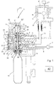
- the filling element generally designated 1 in FIGS. 1 and 2 is a component a filling machine of rotating design and is more similar with a variety Filling elements, each at a uniform angular intervals by a vertical Machine axis distributed on the circumference of a rotor 2 provided.
- a first annular channel 3, a second annular channel 4 and a third annular channel 5 formed, which is the vertical machine axis surround concentrically and provided for all filling elements 1 together are.
- the annular channel 3 as a clamping gas channel
- the annular channel 4 as a vacuum channel
- the annular channel 5 as a return gas channel.
- the annular channel 3 with the gas space 6 ' provided on the rotor 2, partially filled ring boiler 6, the annular channel 4 with a vacuum source or vacuum device or pump 7 and the annular channel 5 with a line 8 for discharging the excess return gas, for example in the atmosphere, in the gas space 6 'or to a device for the treatment of the return gas, and also depending on the respective filling method or system.
- the gas space 6 ' is formed above the level of the liquid level of the filling material in the liquid space 6''.
- a level control 6'' the level N is maintained substantially at a constant value.
- Each filling element 1 is associated with a bottle carrier 9, with which each to filling bottle 10 is raised and with its bottle mouth 10 'in sealing position is pressed and held against an annular seal 13, which at the bottom the filling element 1 or a Fanelementgephinuses 11 is provided and an annular discharge opening 12 encloses.
- a liquid channel 14 formed by a feed 15 with a flow meter 16 with the contents containing the liquid space 6 "of the ring boiler 6 in conjunction stands.
- the liquid valve 17 for the controlled introduction and Terminating the Grestyrenes provided in the bottle 10.
- the liquid valve 17 consists essentially of the valve body 17 ', which on the outer surface of a arranged coaxially with the Grestyrene FA arranged return gas pipe 18 is, which is axially displaceable by a predetermined stroke, and off a valve seat 17 "formed in the fluid channel 14.
- the return gas tube 18 is with its lower end on the underside of the filling element 1 and over the local ring seal 13 before.
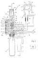
- the flushing pipe 19 is in its extended position, in the the upper end of the flushing pipe 19 and thus also the piston 21 the lower end the chamber 20 are closer than the upper end of this chamber and in the Rinse pipe 19 with a movement stroke of this flushing pipe corresponding length protrudes beyond the lower end of the return gas pipe 18 and relatively far into the interior the bottle 10 is enough.
- a pneumatic actuator 22 for the Liquid valve 17 is provided.
- This actuator 22 consists of the coaxially with the axis FA trained cylinder chamber 22 'is provided, in which a provided on the return gas pipe 18 piston 22 "slidable in the axial direction is provided.
- a control chamber formed via a control valve means, not shown (e.g.
- Solenoid valve controlled by compressed air and can be vented to the piston 22 "and thus also the return gas pipe 18 from that shown in the figure 1 Position corresponding to the opened liquid valve 17, against the effect a compression spring 23 to move in a position which the closed position of Liquid valve 17 corresponds.
- control valve 24 serving as the clamping gas channel annular channel 3 assigned and therefore also referred to as a clamping gas valve
- the control valve 25 is assigned to the serving as a vacuum channel annular channel 4 and therefore Also may be referred to as a vacuum control valve
- the control valve 26 is assigned as a return gas channel annular channel 5 and therefore also as a return gas control valve can be designated.
- Gas way in the sense of the invention means a compound for gas and / or air.
- the aforementioned gas paths 24, 25, 26 and 34 are formed by channels in the housing, wherein the same channels are partially part of different gas paths.
- the check valves 31 and 33 are formed so that they or their valve elements (e.g., ball), for example, by acting on the respective valve member Gravity are biased in the closed state and only at open a predetermined pressure difference in the forward direction.
- the ring bowl 6 is up to the level N with the respective Filled contents.
- the gas space 6 has atmospheric pressure, for example an inert gas or sterile air with atmospheric pressure.
- the filling material is on the open liquid valve 17 in sealing position with the Filling element 1 located bottle 10 is supplied, which displaced from the bottle 10 Gas or the displaced from the bottle 10 air over the return gas tube channel 18 'and via the gas path 28 with the open control valve 25 in the annular channel 4 arrived.
- the throttle 30 provided in the throttle 30 determines the filling speed.
- the check valve 31 arranged parallel to the throttle 30 remains in the closed state.
- Soft drinks and mineral waters with a significant amount of carbon dioxide (CO 2 ) are usually filled with the single-chamber pressure filling system, with biasing of the respective bottle 10.
- the gas space 6 ' contains CO 2 gas at a predetermined, regulated pressure and the liquid space 6 "contains the contents, while the respective bottle 10, which is in sealing position with the filling element 1, is preloaded by opening the control valve 24 via the gas path 27 the annular channel 3 or gas space 6 'and the gas space 18 "and the return gas tube channel 18'.
- the pressure in the space 20 'and the purge pipe 19 is held in its retracted position.
- control valve 24 After biasing, the control valve 24 is closed. Then opens the liquid valve 17 for a slow stuffing, which in this case from the bottle 10 displaced return gas flows through the throttle 35 in the annular channel 5. To the following Fast filling then the control valve 24 is opened again, so that via the return gas tube channel 18 ', the gas space 18 "and the opened gas path 27 a direct connection to the annular channel 3 and thus to the gas space 6 'produced and the filling speed during this fast filling phase by the static Liquid level or the level N is determined in the ring boiler.
- a bias of the respective, in sealing position with the filling element 1 bottle 10 is initially carried out with fresh inert gas.
- fresh inert gas When using carbon dioxide, this leads to high CO 2 levels in the prestressed bottle, so that thus also the oxygen uptake by the contents (beverage) decreases during the filling.
- the bias of the bottle 10 takes place from the gas space 6 'or from the annular channel 3, for which purpose the gas valve 27 is opened to open the gas path 24.
- This purging ensures during the filling phase for optimal CO 2 concentration at economical CO 2 consumption.
- control valve 26 is opened so that CO 2 gas passes under pressure via the gas path 29 and the open control valve 26 and the open check valve 33 in the space 20 "for rinsing the respective, located on the filling element 1 in sealing position bottle 10 bottle
- the piston 21 is moved downwards and thus the flushing pipe 19 is moved into the extended position.
- the CO 2 gas from the annular channel 5 passes through the open gas path 29, the space 20 "and the flushing pipe 19 in the bottle 10.
- control valve 24 is opened with closed control valves 25 and 26, so that via the gas path 27 and the return gas tube channel 18 'CO 2 gas under pressure in the bottle 10 flows, but at the same time also into the space 20 ', whereby the flushing pipe 19 is automatically moved upwards or drawn in via the piston 21.
- the gas space 6 contains CO 2 gas under a predetermined, regulated pressure and the liquid space 6 "contains the contents
- the three-chamber process is carried out as follows:
- the control valve 26 For flushing the respective, located on the filling element 1 in sealing position bottle 10, the control valve 26 is opened, so that CO 2 gas under pressure via the gas path 29 and the open control valve 26 and the open check valve 33 into the space 20 "passes the overpressure building up in the space 20 "causes the piston 21 to move downwards and thus the flushing pipe 19 to the extended position.
- the CO 2 gas from the annular channel 5 passes through the open gas path 29, the space 20 "and the flushing pipe 19 in the bottle 10.
- control valve 24 is opened when the control valve 26 is closed again, so that via the then released gas path 27 and the return gas tube channel 18 'CO 2 gas flows under pressure into the bottle 10 and at the same time by the building up in the space 20' pressure the filling tube 19 is automatically moved to the retracted position.
- the liquid valve 17 is opened, specifically for slow filling, in which again the displaced from the contents of the bottle 10 CO 2 gas via the constantly open throttle 35 flows into the annular channel 5.
- the described construction of the filling element 1, i. especially those by the Control valves 24 - 26 individually controllable gas paths 27, 28 and 29 and the additional Gas path 34 with the constantly open throttle 35 allow in combination with the partially filled ring boiler 6 - only by appropriate program or software selection - also a filling process with pre-evacuation of the respective Bottle 10 and then rinsing, of course, the Number of evacuation steps and purging phases are freely selectable.
- control valve 25 is opened, so that then via the return gas tube channel 18 'and the available gas path 28 available air or existing Gas from the interior of the located in sealing position with the filling element 1 Gas cylinder 10 is aspirated.
- the subsequent filling phase can then be designed in a variety of ways, for example, as in 1.4 above. or 1.5. described, and indeed both in the single-chamber method, as well as in the three-chamber method.
- running are silent drinks, namely, for example still water, fruit juice drinks or wine bottled under atmospheric pressure.
- the gas space 6 has atmospheric pressure, for example an inert gas or sterile Air at atmospheric pressure.
- atmospheric pressure for example an inert gas or sterile Air at atmospheric pressure.
- the gas space contain 6 'CO 2 gas under a predetermined, regulated pressure and the liquid space 6 "the contents.
- control valve 24 opens again, so that then via this opened control valve, the return gas tube channel 18 'and the gas space 18 "a direct, unthrottled connection to the ring channel 3 and thus also to Gas space 6 'is made and so the filling speed by the static Gregutiere (Level N) in the ring vessel 6 is determined.
- the biasing of the present in sealing position with the filling element 1a bottle 10th takes place by opening the control valve 24 directly from the annular channel 3 and the Gas space 6 '.
- control valve 25 is opened so that via the return gas pipe channel 18 ', the gas space 18 "and the throttle 30 an additional Gas flow into the annular channel 4 (vacuum channel) results and thereby the filling speed is increased accordingly. Since the liquid valve 17 in the open position, the control valve 25a is closed.
- the gas space 6 'contains CO 2 gas at a predetermined, regulated pressure and the liquid space 6 "contains the contents
- the annular channel 5 contains CO 2 gas under pressure
- the flushing tubes 19 of all filling elements 1a are moved into their extended position by actuation of all pneumatic cylinders 38.
- the rinsing ensures a high CO2 concentration during the subsequent filling with economical CO 2 consumption. Almost all the carbonic acid flows back into the gas space 6 'of the boiler when filling and can be used for the prestressing of the next bottles.
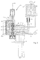
- control valve 26 is opened for flushing, so that CO 2 gas flows from the annular channel 5 via the fully open check valve 33 and the gas chamber 37 into the purge pipe 19 and enters the bottle 10 at the lower end of the purge tube, as this is shown in the figure 4.
- the control valve 25a which is open when the liquid valve 17 is closed, the purge gas is sucked into the annular channel 4.
- the opening of the liquid valve takes place 17 with simultaneous automatic closing of the control valve 25a.
- the control valve 24 is opened, so that then on this Control valve and the gas chamber 18 "and the return gas tube channel 18 'a direct Connection to the annular channel 3 and thus to the gas space 6 'is made and the filling speed again by the static liquid level (level N) in Ring boiler 6 is determined.
- control valve 26 For the subsequent fast filling the control valve 26 is opened, so that a additional second way through the throttle 30 in the annular channel 4 for the displaced Return gas is released and thus sets a higher filling speed.
- control valve 25 which is in series therewith is opened, so that the air or gas from the bottle 10 in sealing position with the filling element 1a is returned via the return gas tube channel 18 ', the gas space 18 "and the gas path 28 is sucked into the annular channel 4.
- control valve 26 is opened again with closed control valve 25 and thus closed gas path 28, so that from the annular channel 5 (return gas channel) CO 2 gas through the fully open check valve 33 and the Rinse pipe 29 flows into the interior of the bottle 10.
- the subsequent filling process can then, for example, as under 2.4. or 2.5. be described described.
- the filling member 1a enables using a corresponding flushing cap 41 also a CIP cleaning of all liquid and gas paths, wherein the cleaning fluid then via the annular channels 4th 5 and fed via the annular channel 3 and the feed 15 in the ring bowl 6 flows and is discharged from this, with open control valves 24-26 and opened liquid valve 17, taking for this particular CIP cleaning by a control common to all filling elements 1a whose control valves 25a are open.
- the particular advantage of the described filling elements 1 and 1a or one with them provided filling machine is thus that an extremely high flexibility and the greatest possible filling comfort can be achieved. With one and the same machine are essentially only by changing the program different filling methods possible, in particular it is then possible that optimal for the respective contents Select filling method. These advantages are despite a low constructive Achieved effort, i. the filling elements 1 and 1a are each only three individually controllable control valves 24 - 26 and a cylinder or actuator 22 required for controlled closing of the liquid valve 17, wherein these elements are controlled by the central control device (filler computer) and be operated.
- Another significant advantage of the invention is also training in that for the extension and retraction of the flushing pipe 19 in the filling element 1 no additional control or control valve is necessary, but this Entry and exit in the manner described automatically by the initiation the rinsing phase (extension of the flushing pipe 19) or by the introduction of the subsequent Vorspannphase (retraction of the purge tube 19) takes place, and that at the filling element 1a a single common to all filling elements of a filling machine Control is sufficient.
- the control of the filling elements 1, 1a and the liquid valves 17 is carried out by the controller generally indicated at 42 in the figures.
Landscapes
- Chemical & Material Sciences (AREA)
- Chemical Kinetics & Catalysis (AREA)
- Physics & Mathematics (AREA)
- Fluid Mechanics (AREA)
- Filling Of Jars Or Cans And Processes For Cleaning And Sealing Jars (AREA)
- Filling Or Discharging Of Gas Storage Vessels (AREA)
- Formation And Processing Of Food Products (AREA)
- Confectionery (AREA)
Description
- Fig. 1
- in vereinfachter Darstellung ein füllrohrloses Füllelement einer Füllmaschine umlaufender Bauart mit einem axial verschiebbaren Spülrohr, zusammen mit einer an dem Füllelement angesetzten Flasche sowie mit einer Teildarstellung eines Rotors und eines teilgefüllten Ringkessels der Füllmaschine, bei eingefahrenem Spülrohr;
- Fig. 2
- eine Darstellung wie Figur 1, jedoch bei in die Flasche ausgefahrenem Spülrohr;
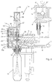
- Fig. 3 und 4
- Darstellungen ähnlich den Figuren 1 und 2 bei einer weiteren möglichen Ausführungsform der Erfindung;
- Fig. 5
- das Füllelement der Figuren 3 und 4 bei der CIP-Reinigung.
Der Gasraum 6' ist über dem Niveau des Flüssigkeitsspiegels des Füllgutes in dem Flüssigkeitsraum 6" gebildet. Durch eine Niveauregelung 6'" wird das Niveau N im wesentlichen auf einem konstanten Wert gehalten.
- Am Füllelement 1a ist zusätzlich zu den Steuerventilen 24, 25 und 26 ein weiteres Steuerventil 25a vorgesehen, welches dem Steuerventil 25 zugeordnet ist und anstelle des Rückschlagventils 31 parallel zur Drossel 30 liegt, d.h. bei geöffnetem Steuerventil 25a wird die Drossel 30 überbrückt.
- In Reihe mit der Drossel 35 ist ein Rückschlagventil 36 in dem den Ringkanal 5 mit dem Gasraum 18" ständig verbindenden Gasweg vorgesehen ist, wobei das Rückschlagventil 36 so ausgebildet ist, daß es für eine Strömung aus dem Gasraum 18" in den Ringkanal 5 öffnet und für eine Strömung in umgekehrter Richtung sperrt.
- Bei dem Füllelement 1a fehlen die Zylinderkammer 20 und der Kolben 21 zum Ein- und Ausfahren des Spülrohres 19.
- Der Gasweg 29, in dem das Steuerventil 26 vorgesehen ist, mündet in einen im Gehäuse 11a des Füllelementes 1a gebildeten Gasraum 37, der sich oberhalb des Gasraumes 18" befindet, von diesem aber getrennt ist.
- Durch den Gasraum 37 erstreckt sich das Spülrohr 19 hindurch, und zwar derart, daß der Spülrohrkanal 19' mit seinem oberen Ende sowohl bei eingefahrenem Spülrohr (Figur 3), als auch bei ausgefahrenem Spülrohr (Figur 4) in den Gasraum 37 mündet.
- Zum Ein- und Ausfahren des Spülrohres 19 ist an der Oberseite des Gehäuses 11a über dem Gasraum 37 zusätzlich ein doppelt wirkender Pneumatik-Zylinder 38 mit Kolben 39 und mit einer mit dem oberen Ende des Spülrohres 19 verbundenen Kolbenstange 40 vorgesehen.
- Die Ansteuerung des pneumatisch betätigten Steuerventils 25a erfolgt für jedes Füllelement 1a individuell, und zwar über ein Magnetventil, welches auch das von dem Zylinderraum 22 und dem Kolben 23 gebildete Betätigungselement des Flüssigkeitsventils 17 steuert, und zwar derart, daß das Steuerventil 25a immer dann öffnet, wenn das Flüssigkeitsventil 17 geschlossen ist.
- 1, 1a
- Füllelement
- 2
- Rotor
- 3, 4, 5
- Ringkanal
- 6
- Ringkessel
- 6'
- Gasraum
- 6"
- Flüssigkeitsraum
- 6'"
- Niveauregler
- 7
- Vakuumpumpe
- 8
- Leitung
- 9
- Flaschenträger
- 10
- Flasche
- 11, 11a
- Füllelementgehäuse
- 12
- Abgabeöffnung
- 13
- Ringdichtung
- 14
- Flüssigkeitskanal
- 15
- Verbindung
- 16
- Durchflußmesser
- 17
- Flüssigkeitsventil
- 17'
- Ventilkörper
- 17"
- Ventilsitz
- 18
- Rückgasrohr
- 18'
- Rückgasrohrkanal
- 18"
- Gasraum
- 18'"
- Rückgasöffnung
- 19
- Spülrohr
- 19'
- Spülrohrkanal
- 20
- Zylinderkammer
- 20', 20"
- Raum
- 21
- Kolben
- 22
- Betätigungselement
- 22'
- Zylinderraum
- 22"
- Kolben
- 23
- Druckfeder
- 24
- Steuerventil
- 25, 25a
- Steuerventil
- 26
- Steuerventil
- 27, 28, 29
- Gasweg
- 30
- Drossel
- 31
- Rückschlagventil
- 32
- Drossel
- 33
- Rückschlagventil
- 34
- zusätzlicher Gasweg
- 35
- Drossel
- 36
- Rückschlagventil
- 37
- Gasraum
- 38
- Pneumatikzylinder
- 39
- Kolben
- 40
- Kolbenstange
- 41
- Spülkappe
- 42
- Steuereinrichtung
- FA
- Füllelementachse
- N
- Füllgutniveau im Ringkessel
Claims (27)
- Füllmaschine umlaufender Bauart zum Füllen von Flaschen, Dosen oder dergleichen Behälter (10) mit einem flüssigen Füllgut, mit mehreren an einem Rotor (2) gebildeten Füllpositionen mit jeweils einem Füllelement (1, 1a), gegen welches der jeweilige Behälter (10) beim Füllen mit einer Behältermündung (10') im Bereich einer Füllelement-Abgabeöffnung (12) angesetzt ist, die Teil eines im Füllelement (1,1a) ausgebildeten Flüssigkeitsweges (14) mit Flüssigkeitsventil (17) ist, wobei das jeweilige Füllelement (1, 1a) wenigstens eine Rückgasöffnung (18''') aufweist, über die der Innenraum des Behälters (10) mit im Füllelement (1, 1a) ausgebildeten und durch Steuerventile (24, 25, 25a, 26) steuerbaren Gaswegen verbindbar ist, mit einem Kessel (6), der einen Flüssigkeitsraum (6") zur Aufnahme des Füllguts und darüber einen Gasraum (6') bildet, sowie mit wenigstens drei für sämtliche Füllelemente (1, 1a) gemeinsamen Kanälen (3, 4, 5) am Rotor (2), die einen Spanngaskanal (3), einen Vakuumkanal (4) und einen Rückgaskanal (5) bilden, sowie mit drei Gaswegen (27, 28, 29), nämlich ein erster Gasweg (27), der ein erstes Steuerventil (24) aufweist, und über den eine gesteuerte Verbindung zwischen der Rückgasöffnung (18'") und dem Spanngaskanal (3) herstellbar ist, ein zweiter Gasweg (28), der ein zweites Steuerventil (25) aufweist und über den eine gesteuerte Verbindung zwischen der Rückgasöffnung (18'") und dem Vakuumkanal (4) herstellbar ist, einen dritten Gasweg (29), der ein drittes Steuerventil (26) aufweist und über den eine gesteuerte Verbindung zwischen dem Rückgaskanal (5) und einem am Füllelement (1, 1a) vorgesehenen und in den jeweiligen Behälter (10) einführbaren Spülrohr (19) herstellbar ist, dadurch gekennzeichnet, dass im Füllelement (1, 1a) wenigstens ein vierter Gasweg (34), der eine erste, den Gasfluß regelnde oder reduzierende Drossel (35) enthält und über den eine ständige Verbindung zwischen der Rückgasöffnung (18"') und dem Rückgaskanal (5) besteht, und dass im zweiten Gasweg (28) eine zweite Drossel (30) und im dritten Gasweg (29) eine dritte Drossel (32) vorgesehen sind.
- Füllmaschine nach Anspruch 1, gekennzeichnet durch eine pneumatische Betätigungseinrichtung (20, 21; 38) zum axialen Bewegen des Spülrohres (19) aus einer eingefahrenen Position, in der das Spülrohr (19) nicht oder nur mit einer kürzeren Länge über das Füllelement (1, 1a) vorsteht, und einer ausgefahrenen Stellung, in der das Spülrohr (19) mit einer größeren Länge über das Füllelement (1, 1a) vorsteht.
- Füllmaschine nach Anspruch 2 dadurch gekennzeichnet, daß das pneumatische Betätigungselement einen am Spülrohr (19) befestigten Kolben (21) aufweist, der in einem im Füllelement (1) ausgebildeten Zylinderraum (20) axial verschiebbar ist und diesen Zylinderraum in Teilräume (20', 20") unterteilt, von denen ein erster Teilraum (20') zum Einfahren des Spülrohres (19) und ein zweiter Teilraum (20") zum Ausfahren des Spülrohres (19) mit Druck beaufschlagbar sind, daß der erste Teilraum (20') mit einem zu der Rückgasöffnung (18''') führenden Teil zumindest des ersten Gasweges (27) und/oder des vierten Gasweges (34) in Verbindung steht, und der zweiter Teilraum (20") mit dem dritten Gasweg (29) in Verbindung steht.
- Füllmaschine nach Anspruch 2, dadurch gekennzeichnet, daß das pneumatische Betätigungselement für das Spülrohr (19) von einem Pneumatik-Zylinder (38) gebildet ist und daß die Pneumatik-Zylinder (38) sämtlicher Füllelemente (1a) der Füllmaschine von einem gemeinsamen Pneumatik-Ventil gesteuert werden.
- Füllmaschine nach einem der vorhergehenden Ansprüche, daß die erste Drossel (35) in Serie mit einem Rückschlagventil (36) vorgesehen ist, welches für einen Gasstrom von der Rückgasöffnung (18''') in den Rückgaskanal (5) öffnet, für eine Gasströmung in umgekehrter Richtung sperrt.
- Füllmaschine nach einem der vorhergehenden Ansprüche, dadurch gekennzeichnet, daß parallel zur zweiten Drossel (30) ein zweites Rückschlagventil (31) vorgesehen ist, welches für einen Gasstrom von der Rückgasöffnung (18''') in den Vakuumkanal (4) öffnet, für eine Gasströmung in umgekehrter Richtung aber sperrt.
- Füllmaschine nach einem der vorhergehenden Ansprüche, daß parallel zur dritten Drossel (32) ein drittes Rückschlagventil (33) vorgesehen ist, welches für eine Strömung aus dem Rückgaskanal (5) in das Spülrohr (19) oder einen dortigen Spülrohrkanal (19') öffnet, für eine Strömung in umgekehrter Richtung aber sperrt.
- Füllmaschine nach einem der vorhergehenden Ansprüche, dadurch gekennzeichnet, daß parallel zur zweiten Drossel (30) ein weiteres Steuerventil (25a) vorgesehen ist, und daß die Parallelschaltung aus der zweiten Drossel (30) und dem weiteren Steuerventil (25a) in Serie mit dem zweiten Steuerventil (25) im zweiten Gasweg (28) liegt.
- Füllmaschine nach einem der vorhergehenden Ansprüche, dadurch gekennzeichnet, daß das Füllelement (1, 1a) ein füllrohrloses Füllelement ist, und daß die Rückgasöffnung (18''') von der Öffnung eines Rückgasrohres (18) gebildet ist, welches von der Abgabeöffnung (12) umgeben ist und bei an das Füllelement (1, 1a) angesetztem Behälter (10) durch die Behälteröffnung (10') in den Behälterinnenraum hineinreicht.
- Füllmaschine nach Anspruch 9, dadurch gekennzeichnet, daß das Rückgasrohr (18) das Spülrohr (19) unter Bildung eines ringförmigen Rückgasrohrkanales (18') mit Abstand umschließt.
- Füllmaschine nach Anspruch 9, dadurch gekennzeichnet, daß der erste Gasweg (27), der zweite Gasweg (28) sowie der vierte Gasweg (34) jeweils mit einem in dem Rückgasrohr (18) gebildeten Rückgasrohrkanal (18') in Verbindung stehen, vorzugsweise über einen im Füllelement (1, 1a) ausgebildeten zusätzlichen Gasraum (18").
- Füllmaschine nach einem der vorhergehenden Ansprüche, dadurch gekennzeichnet, daß der Spanngaskanal (3) mit dem Gasraum (6') des Kessels (6) in Verbindung steht oder mit diesem verbindbar ist.
- Füllmaschine nach einem der vorhergehenden Ansprüche 9-12, dadurch gekennzeichnet, daß das Flüssigkeitsventil (17) von einem am Rückgasrohr (18) vorgesehenen Ventilkörper (17') und von einem mit diesem Ventilkörper im Flüssigkeitsweg (14) vorgesehenen Ventilsitz (17") gebildet ist, und daß das Rückgasrohr (18) durch eine Betätigungseinrichtung (22) zum Öffnen und Schließen des Flüssigkeitsventils (17) axial um einen vorgegebenen Hub bewegbar ist.
- Füllmaschine nach einem der vorhergehenden Ansprüche, dadurch gekennzeichnet, daß in der Verbindung zwischen dem Flüssigkeitsraum (6") des Kessels (6) und dem Flüssigkeitsweg (14) des jeweiligen Füllelementes (1, 1a) ein Durchflußmesser (16) für das Füllgut vorgesehen ist.
- Füllmaschine nach einem der vorhergehenden Ansprüche, dadurch gekennzeichnet, daß die Steuerventile (24, 25, 25a, 26) pneumatisch betätigbare Ventile, vorzugsweise Membran-Ventile sind.
- Füllmaschine nach einem der vorhergehenden Ansprüche 8-15, dadurch gekennzeichnet, daß das zusätzliche Steuerventil (25a) in Abhängigkeit von dem Flüssigkeitsventil (17) des betreffenden Füllelementes (1a) derart gesteuert wird, daß dieses zusätliche Steuerventil (25a) sich in der geöffneten Stellung befindet, wenn das Flüssigkeitsventil (17) geschlossen ist, und sich in der geschlossenen Stellung befindet, wenn das Flüssigkeitsventil (17) geöffnet ist.
- Füllmaschine nach einem der vorhergehenden Ansprüche 3-16, dadurch gekennzeichnet, daß der zweite Zylinderraum (20") mit dem zwischen dem dritten Steuerventil (26) und dem Spülrohr (19) liegenden Teil des dritten Gasweges (29) verbunden ist.
- Füllmaschine nach einem der vorhergehenden Ansprüche, dadurch gekennzeichnet, daß die zweite Drossel (30) in dem zwischen dem zweiten Steuerventil (25) und dem Vakuum-Kanal (4) gebildeten Abschnitt des zweiten Gasweges (28) vorgesehen ist.
- Füllmaschine nach einem der vorhergehenden Ansprüche, dadurch gekennzeichnet, daß die dritte Drossel (32) in dem zwischen dem dritten Steuerventil (26) und dem Rückgaskanal (5) gebildeten Teil des dritten Gasweges (29) vorgesehen ist.
- Füllmaschine nach einem der vorhergehenden Ansprüche, gekennzeichnet durch eine die Füllelemente (1, 1a) bzw. deren Steuerventile (24, 25, 26) steuernde Steuereinrichtung (42), die durch Programm-Änderung unterschiedliche Füllverfahren ermöglicht.
- Füllmaschine nach Anspruch 20, dadurch gekennzeichnet, daß die Steuereinrichtung (42) für eine drucklose Füllung , insbesondere von stillen Getränken bei geöffnetem Flüssigkeitsventil (17) das zweite Steuerventil(25) öffnet, um einen von dem flüssigen Füllgut verdrängten Luft- und/oder Gasstrom aus dem Behälter (10) über die Rückgasöffnung (18'") und den zweiten Gasweg (28) in den Vakuumkanal (4) zu ermöglichen.
- Füllmaschine nach Anspruch 20, dadurch gekennzeichnet, daß die Steuereinrichtung (42) für eine drucklose Füllung, insbesondere von stillen Getränken das dritte Steuerventil (26) öffnet, um bei geöffnetem Flüssigkeitsventil (17) einen Luftund/oder Gasstrom aus dem Inneren des Behälters (10) über das Spülrohr in den Rückgaskanal (5) zu ermöglichen.
- Füllmaschine nach Anspruch 20, dadurch gekennzeichnet, daß die Steuereinrichtung (42) für eine Einkammer-Druckfüllung zum Vorspannen des jeweiligen an einem Füllelement (1, 1a) in Dichtlage befindlichen Behälters (10) das erste Steuerventil (24) öffnet, um den Innenraum des Behälters (10) über den ersten Gasweg aus dem Spanngaskanal (3) mit Inert-Gas vorzuspannen, daß die Steuereinrichtung (42) anschließend für ein langsames Anfüllen nach dem Schließen des ersten Steuerventils (24) das Flüssigkeitsventil (17) öffnet, so daß das aus dem Behälter (10) verdrängte Rückgas über den vierten Gasweg in den Rückgaskanal (5) abfließt, und daß die Steuereinrichtung (42) für ein anschließendes Schnellfüllen das erste Steuerventil (24) wieder öffnet, um damit eine Verbindung des Behälterinnenraums über die Rückgasöffnung (18'") mit dem mit dem Gasraum (6') des Kessels (6) in Verbindung stehenden Spanngaskanal (3) herzustellen.
- Füllmaschine nach Anspruch 20, dadurch gekennzeichnet, daß für ein Dreikammer-Druckfüllen, insbesondere von sauerstoffempfindlichen und/oder mikrobiologisch kritischen CO2-haltigen Getränken die Steuereinrichtung (42) zunächst zum Vorspannen des jeweiligen in Dichtlage mit dem Füllelement (1, 1a) befindlichen Behälters (10) mit frischem Inert-Gas das erste Steuerventil (24) öffnet, daß die Steuereinrichtung (42) anschließend nach dem Schließen des ersten Steuerventils (26) zum längsamen Anfüllen das Flüssigkeitsventil (17) öffnet, so daß das verdrängte Rückgas über den vierten Gasweg in den Rückgaskanal (5) abfließt, und daß die Steuereinrichtung (42) zum anschließenden Schnellfüllen das dritte Steuerventil (26) öffnet, so daß das beim weiteren Füllen des Behälters (10) aus diesem verdrängte Rückgas nunmehr über das Spülrohr und den geöffneten dritten Gasweg in den Rückgaskanal (5) strömen kann.
- Füllmaschine nach einem der Ansprüche 20 bis 24, dadurch gekennzeichnet, daß für eine sauerstoffarme Füllung im Einkammer-Verfahren, insbesondere Bierfüllung die Steuereinrichtung (42) das dritte Steuerventil (26) zum Spülen des Innenraums des in Dichtlage mit dem Füllelement (1, 1a) befindlichen Behälters (10) mit inertGas aus dem Rückgaskanal (5) öffnet.
- Füllmaschine nach einem der Ansprüche 20 bis 25, dadurch gekennzeichnet, daß die Steuereinrichtung (42) zum Spülen des jeweils in Dichtlage mit dem Füllelement (1, 1a) befindlichen Behälters (10) mit Inert-Gas aus dem Rückgaskanal (5) sowie gegebenenfalls auch zum Ausfahren des Spülrohres (19) das dritte Steuerventil (26) öffnet.
- Füllmaschine nach einem der Ansprüche 20 bis 26, dadurch gekennzeichnet, daß die Steuereinrichtung (42) für ein Evakuieren des in Dichtlage mit dem Füllelement (1, 1a) befindlichen Behälters das zweite Steuerventil (25) öffnet und in einer anschließenden Spülphase zum Spülen des jeweiligen Behälters (10) mit Inert-Gas aus dem Rückgaskanal (5) das dritte Steuerventil (26) öffnet.
Applications Claiming Priority (2)
| Application Number | Priority Date | Filing Date | Title |
|---|---|---|---|
| DE10064954 | 2000-12-23 | ||
| DE10064954A DE10064954A1 (de) | 2000-12-23 | 2000-12-23 | Füllmaschine |
Publications (3)
| Publication Number | Publication Date |
|---|---|
| EP1216952A2 EP1216952A2 (de) | 2002-06-26 |
| EP1216952A3 EP1216952A3 (de) | 2002-08-21 |
| EP1216952B1 true EP1216952B1 (de) | 2004-04-07 |
Family
ID=7668935
Family Applications (1)
| Application Number | Title | Priority Date | Filing Date |
|---|---|---|---|
| EP01120679A Expired - Lifetime EP1216952B1 (de) | 2000-12-23 | 2001-09-03 | Füllmaschine |
Country Status (3)
| Country | Link |
|---|---|
| EP (1) | EP1216952B1 (de) |
| AT (1) | ATE263733T1 (de) |
| DE (2) | DE10064954A1 (de) |
Cited By (1)
| Publication number | Priority date | Publication date | Assignee | Title |
|---|---|---|---|---|
| DE102007040262A1 (de) | 2007-08-24 | 2009-02-26 | Khs Ag | Füllelement und Verfahren zur sauerstoffarmen Füllung großvolumiger Behälter mit einem flüssigen Füllgut |
Families Citing this family (21)
| Publication number | Priority date | Publication date | Assignee | Title |
|---|---|---|---|---|
| JP4701542B2 (ja) * | 2001-05-31 | 2011-06-15 | 澁谷工業株式会社 | 充填装置とその充填方法 |
| DE102004015167B3 (de) * | 2004-03-27 | 2005-11-03 | Khs Maschinen- Und Anlagenbau Ag | Füllelement |
| DE102004017205A1 (de) | 2004-04-10 | 2005-10-27 | Khs Maschinen- Und Anlagenbau Ag | Füllmaschine umlaufender Bauart |
| DE102007009435A1 (de) | 2007-02-23 | 2008-08-28 | Khs Ag | Verfahren zum Füllen von Flaschen oder dergleichen Behälter mit einem flüssigen Füllgut unter Gegendruck sowie Füllmaschine zum Durchführen dieses Verfahrens |
| WO2009123493A1 (ru) * | 2008-04-01 | 2009-10-08 | Закрытое Акционерное Общество "Новосибирскпродмаш" | Устройство для ручного розлива пенящихся и/или газированных напитков |
| IT1392774B1 (it) * | 2009-02-13 | 2012-03-23 | Four One S R L | Apparato e procedimento per il riempimento di un contenitore. |
| US20120138192A1 (en) * | 2009-06-05 | 2012-06-07 | Simone Campi | Filling machine and method of filling a container |
| RU2482054C2 (ru) * | 2009-06-11 | 2013-05-20 | Сергей Дмитриевич Филиппов | Устройство для ручного розлива, газирования и укупорки под давлением пенящихся или газированных напитков |
| DE102010009138A1 (de) * | 2010-02-23 | 2011-08-25 | Krones Ag, 93073 | Befüllungsanlage zum Befüllen von Behältnissen und Betriebsverfahren für eine Befüllungsanlage zum Befüllen von Behältnissen |
| DE102012008755A1 (de) * | 2012-05-04 | 2013-11-07 | Khs Gmbh | Hubvorrichtung für Behälterbehandlungsmaschinen, Behälterbehandlungsmaschine mit einer solchen Hubvorrichtung sowie Verfahren zum Füllen von Behältern |
| DE102013102547A1 (de) | 2013-03-13 | 2014-09-18 | Khs Gmbh | Verfahren sowie Füllmaschine zum Füllen von Dosen oder dgl. Behältern mit einem flüssigen Füllgut |
| DE102013103639A1 (de) | 2013-04-11 | 2014-10-16 | Khs Gmbh | Füllelement, Füllsystem sowie Verfahren zum Füllen von Behältern |
| DE102013104938A1 (de) * | 2013-05-14 | 2014-11-20 | Khs Gmbh | Füllsystem sowie Füllmaschine zum Füllen von Behältern |
| EP2871150B1 (de) * | 2013-11-08 | 2017-02-01 | Sidel S.p.a. Con Socio Unico | Fülleinheit und Verfahren zum Füllen eines Gegenstandes mit einem fließfähigen Produkt |
| DE102014104873A1 (de) * | 2014-04-04 | 2015-10-08 | Krones Ag | Verfahren und Vorrichtung zum Befüllen eines Behälters mit einem Füllprodukt |
| DE102015111374A1 (de) | 2015-07-14 | 2017-01-19 | Krones Ag | Vorrichtung und Verfahren zum Einleiten eines Gases in einen mit einem Füllprodukt zu befüllenden Behälter |
| EP3184484B1 (de) * | 2015-12-22 | 2019-10-09 | Sidel Participations, S.A.S. | Füllvorrichtung zum befüllen mit oder ohne kontakt eines artikels mit einem fliessfähigen produkt |
| CN106365099A (zh) * | 2016-10-21 | 2017-02-01 | 张家港市万金机械有限公司 | 一种瓶体灌水阀 |
| DE102020130628A1 (de) | 2020-11-19 | 2022-05-19 | Krones Aktiengesellschaft | Multifunktionale Vorrichtung zum Befüllen von Behältern mit einem Füllprodukt |
| JP7294310B2 (ja) * | 2020-12-25 | 2023-06-20 | 大日本印刷株式会社 | 飲料充填システム及びcip処理方法 |
| CN112758372A (zh) * | 2020-12-30 | 2021-05-07 | 武汉交通职业学院 | 化成碱液自动灌装设备及其灌装方法 |
Family Cites Families (2)
| Publication number | Priority date | Publication date | Assignee | Title |
|---|---|---|---|---|
| DE29510860U1 (de) * | 1995-07-05 | 1995-10-12 | KHS Maschinen- und Anlagenbau AG, 44143 Dortmund | Füllelement |
| DE19939521B4 (de) * | 1999-03-04 | 2005-10-20 | Khs Masch & Anlagenbau Ag | Verfahren zur sauerstoffarmen Abfüllung von Getränken |
-
2000
- 2000-12-23 DE DE10064954A patent/DE10064954A1/de not_active Withdrawn
-
2001
- 2001-09-03 DE DE50101898T patent/DE50101898D1/de not_active Expired - Lifetime
- 2001-09-03 AT AT01120679T patent/ATE263733T1/de not_active IP Right Cessation
- 2001-09-03 EP EP01120679A patent/EP1216952B1/de not_active Expired - Lifetime
Cited By (1)
| Publication number | Priority date | Publication date | Assignee | Title |
|---|---|---|---|---|
| DE102007040262A1 (de) | 2007-08-24 | 2009-02-26 | Khs Ag | Füllelement und Verfahren zur sauerstoffarmen Füllung großvolumiger Behälter mit einem flüssigen Füllgut |
Also Published As
| Publication number | Publication date |
|---|---|
| ATE263733T1 (de) | 2004-04-15 |
| DE10064954A1 (de) | 2002-06-27 |
| DE50101898D1 (de) | 2004-05-13 |
| EP1216952A3 (de) | 2002-08-21 |
| EP1216952A2 (de) | 2002-06-26 |
Similar Documents
| Publication | Publication Date | Title |
|---|---|---|
| EP1216952B1 (de) | Füllmaschine | |
| EP0953541B1 (de) | Füllsystem sowie Füllelement | |
| EP1584601B1 (de) | Füllmaschine umlaufender Bauart | |
| EP0697369B1 (de) | Verfahren zum Abfüllen eines flüssigen Füllgutes in Flaschen oder dgl. Behälter | |
| EP0365867B1 (de) | Verfahren und Vorrichtung zum Befüllen von Gertränkedosen | |
| DE10359492B3 (de) | Füllelement für eine Füllmaschine | |
| EP1162167B1 (de) | Verfahren zum Füllen von Flaschen, Dosen oder dergleichen Behälter mit einem flüssigen Füllgut sowie Füllmaschine | |
| DE102004015167B3 (de) | Füllelement | |
| EP0979797B1 (de) | Füllsystem | |
| DE102010032573A1 (de) | Füllmaschine | |
| DE69218540T2 (de) | Verfahren und Vorrichtung zum Befüllen von Getränkedosen | |
| EP0953542B1 (de) | Füllventil für eine Abfüllanlage | |
| EP2307306B1 (de) | Füllsystem zum füllen von flaschen oder dergleichen behältern sowie füllmaschine | |
| DE3446501C2 (de) | ||
| DE20319789U1 (de) | Füllmaschine mit separatem Rückgaskanal | |
| DE102013104938A1 (de) | Füllsystem sowie Füllmaschine zum Füllen von Behältern | |
| DE102005003222A1 (de) | Vorrichtung zum Füllen von Gefäßen | |
| EP1270499B1 (de) | Füllrohrloses Füllelement für eine Füllmaschine zum sauerstoffarmen Abfüllen eines Getränks | |
| DE10359312B4 (de) | Füllmaschine zum Füllen von Behältern | |
| DE4402980C1 (de) | Füllsystem zum Abfüllen eines flüssigen Füllgutes in Flaschen, Dosen oder dgl. Behälter | |
| EP0705788B1 (de) | Verfahren zum Abfüllen eines flüssigen Füllgutes in Flaschen oder dergl. Behälter | |
| EP2576420A1 (de) | Füllelement sowie füllmaschine zum füllen von flaschen oder dergleichen behältern | |
| DE20319619U1 (de) | Füllmaschine zum Füllen von Behältern | |
| WO2021213840A1 (de) | Verfahren zum befüllen von behältern | |
| DE3819349C2 (de) | Verfahren und Vorrichtung zum Abfüllen von gashaltigen Getränken in Flaschen |
Legal Events
| Date | Code | Title | Description |
|---|---|---|---|
| PUAI | Public reference made under article 153(3) epc to a published international application that has entered the european phase |
Free format text: ORIGINAL CODE: 0009012 |
|
| 17P | Request for examination filed |
Effective date: 20010926 |
|
| AK | Designated contracting states |
Kind code of ref document: A2 Designated state(s): AT BE CH CY DE DK ES FI FR GB GR IE IT LI LU MC NL PT SE TR |
|
| AX | Request for extension of the european patent |
Free format text: AL;LT;LV;MK;RO;SI |
|
| PUAL | Search report despatched |
Free format text: ORIGINAL CODE: 0009013 |
|
| AK | Designated contracting states |
Kind code of ref document: A3 Designated state(s): AT BE CH CY DE DK ES FI FR GB GR IE IT LI LU MC NL PT SE TR |
|
| AX | Request for extension of the european patent |
Free format text: AL;LT;LV;MK;RO;SI |
|
| 17Q | First examination report despatched |
Effective date: 20021125 |
|
| AKX | Designation fees paid |
Designated state(s): AT BE CH CY DE DK ES FI FR GB GR IE IT LI LU MC NL PT SE TR |
|
| GRAH | Despatch of communication of intention to grant a patent |
Free format text: ORIGINAL CODE: EPIDOS IGRA |
|
| GRAS | Grant fee paid |
Free format text: ORIGINAL CODE: EPIDOSNIGR3 |
|
| GRAA | (expected) grant |
Free format text: ORIGINAL CODE: 0009210 |
|
| AK | Designated contracting states |
Kind code of ref document: B1 Designated state(s): AT BE CH CY DE DK ES FI FR GB GR IE IT LI LU MC NL PT SE TR |
|
| PG25 | Lapsed in a contracting state [announced via postgrant information from national office to epo] |
Ref country code: TR Free format text: LAPSE BECAUSE OF FAILURE TO SUBMIT A TRANSLATION OF THE DESCRIPTION OR TO PAY THE FEE WITHIN THE PRESCRIBED TIME-LIMIT Effective date: 20040407 Ref country code: CY Free format text: LAPSE BECAUSE OF FAILURE TO SUBMIT A TRANSLATION OF THE DESCRIPTION OR TO PAY THE FEE WITHIN THE PRESCRIBED TIME-LIMIT Effective date: 20040407 Ref country code: FI Free format text: LAPSE BECAUSE OF FAILURE TO SUBMIT A TRANSLATION OF THE DESCRIPTION OR TO PAY THE FEE WITHIN THE PRESCRIBED TIME-LIMIT Effective date: 20040407 Ref country code: IE Free format text: LAPSE BECAUSE OF FAILURE TO SUBMIT A TRANSLATION OF THE DESCRIPTION OR TO PAY THE FEE WITHIN THE PRESCRIBED TIME-LIMIT Effective date: 20040407 |
|
| REG | Reference to a national code |
Ref country code: GB Ref legal event code: FG4D Free format text: NOT ENGLISH |
|
| REG | Reference to a national code |
Ref country code: CH Ref legal event code: EP |
|
| REF | Corresponds to: |
Ref document number: 50101898 Country of ref document: DE Date of ref document: 20040513 Kind code of ref document: P |
|
| REG | Reference to a national code |
Ref country code: IE Ref legal event code: FG4D Free format text: GERMAN |
|
| PG25 | Lapsed in a contracting state [announced via postgrant information from national office to epo] |
Ref country code: SE Free format text: LAPSE BECAUSE OF FAILURE TO SUBMIT A TRANSLATION OF THE DESCRIPTION OR TO PAY THE FEE WITHIN THE PRESCRIBED TIME-LIMIT Effective date: 20040707 Ref country code: GR Free format text: LAPSE BECAUSE OF FAILURE TO SUBMIT A TRANSLATION OF THE DESCRIPTION OR TO PAY THE FEE WITHIN THE PRESCRIBED TIME-LIMIT Effective date: 20040707 Ref country code: DK Free format text: LAPSE BECAUSE OF FAILURE TO SUBMIT A TRANSLATION OF THE DESCRIPTION OR TO PAY THE FEE WITHIN THE PRESCRIBED TIME-LIMIT Effective date: 20040707 |
|
| PG25 | Lapsed in a contracting state [announced via postgrant information from national office to epo] |
Ref country code: ES Free format text: LAPSE BECAUSE OF FAILURE TO SUBMIT A TRANSLATION OF THE DESCRIPTION OR TO PAY THE FEE WITHIN THE PRESCRIBED TIME-LIMIT Effective date: 20040718 |
|
| GBT | Gb: translation of ep patent filed (gb section 77(6)(a)/1977) |
Effective date: 20040715 |
|
| PG25 | Lapsed in a contracting state [announced via postgrant information from national office to epo] |
Ref country code: AT Free format text: LAPSE BECAUSE OF NON-PAYMENT OF DUE FEES Effective date: 20040903 Ref country code: LU Free format text: LAPSE BECAUSE OF NON-PAYMENT OF DUE FEES Effective date: 20040903 |
|
| PG25 | Lapsed in a contracting state [announced via postgrant information from national office to epo] |
Ref country code: MC Free format text: LAPSE BECAUSE OF NON-PAYMENT OF DUE FEES Effective date: 20040930 |
|
| REG | Reference to a national code |
Ref country code: IE Ref legal event code: FD4D |
|
| ET | Fr: translation filed | ||
| PLBE | No opposition filed within time limit |
Free format text: ORIGINAL CODE: 0009261 |
|
| STAA | Information on the status of an ep patent application or granted ep patent |
Free format text: STATUS: NO OPPOSITION FILED WITHIN TIME LIMIT |
|
| 26N | No opposition filed |
Effective date: 20050110 |
|
| PG25 | Lapsed in a contracting state [announced via postgrant information from national office to epo] |
Ref country code: LI Free format text: LAPSE BECAUSE OF NON-PAYMENT OF DUE FEES Effective date: 20050930 Ref country code: CH Free format text: LAPSE BECAUSE OF NON-PAYMENT OF DUE FEES Effective date: 20050930 |
|
| REG | Reference to a national code |
Ref country code: CH Ref legal event code: PL |
|
| PG25 | Lapsed in a contracting state [announced via postgrant information from national office to epo] |
Ref country code: PT Free format text: LAPSE BECAUSE OF NON-PAYMENT OF DUE FEES Effective date: 20040907 |
|
| REG | Reference to a national code |
Ref country code: NL Ref legal event code: TD Effective date: 20111114 |
|
| REG | Reference to a national code |
Ref country code: FR Ref legal event code: CD Owner name: KHS GMBH Effective date: 20111122 Ref country code: FR Ref legal event code: CD Owner name: KHS GMBH Effective date: 20111121 |
|
| BECN | Be: change of holder's name |
Owner name: KHS G.M.B.H. Effective date: 20120314 |
|
| REG | Reference to a national code |
Ref country code: FR Ref legal event code: PLFP Year of fee payment: 16 |
|
| REG | Reference to a national code |
Ref country code: FR Ref legal event code: PLFP Year of fee payment: 17 |
|
| PGFP | Annual fee paid to national office [announced via postgrant information from national office to epo] |
Ref country code: IT Payment date: 20170926 Year of fee payment: 17 Ref country code: DE Payment date: 20170928 Year of fee payment: 17 Ref country code: FR Payment date: 20170928 Year of fee payment: 17 Ref country code: GB Payment date: 20170921 Year of fee payment: 17 |
|
| PGFP | Annual fee paid to national office [announced via postgrant information from national office to epo] |
Ref country code: BE Payment date: 20170921 Year of fee payment: 17 Ref country code: NL Payment date: 20170921 Year of fee payment: 17 |
|
| REG | Reference to a national code |
Ref country code: DE Ref legal event code: R119 Ref document number: 50101898 Country of ref document: DE |
|
| REG | Reference to a national code |
Ref country code: NL Ref legal event code: MM Effective date: 20181001 |
|
| GBPC | Gb: european patent ceased through non-payment of renewal fee |
Effective date: 20180903 |
|
| REG | Reference to a national code |
Ref country code: BE Ref legal event code: MM Effective date: 20180930 |
|
| PG25 | Lapsed in a contracting state [announced via postgrant information from national office to epo] |
Ref country code: NL Free format text: LAPSE BECAUSE OF NON-PAYMENT OF DUE FEES Effective date: 20181001 |
|
| PG25 | Lapsed in a contracting state [announced via postgrant information from national office to epo] |
Ref country code: IT Free format text: LAPSE BECAUSE OF NON-PAYMENT OF DUE FEES Effective date: 20180903 Ref country code: DE Free format text: LAPSE BECAUSE OF NON-PAYMENT OF DUE FEES Effective date: 20190402 |
|
| PG25 | Lapsed in a contracting state [announced via postgrant information from national office to epo] |
Ref country code: BE Free format text: LAPSE BECAUSE OF NON-PAYMENT OF DUE FEES Effective date: 20180930 Ref country code: FR Free format text: LAPSE BECAUSE OF NON-PAYMENT OF DUE FEES Effective date: 20180930 |
|
| PG25 | Lapsed in a contracting state [announced via postgrant information from national office to epo] |
Ref country code: GB Free format text: LAPSE BECAUSE OF NON-PAYMENT OF DUE FEES Effective date: 20180903 |