EP1217187A1 - Circuit d'admission d'air d'un moteur suralimenté - Google Patents
Circuit d'admission d'air d'un moteur suralimenté Download PDFInfo
- Publication number
- EP1217187A1 EP1217187A1 EP01403247A EP01403247A EP1217187A1 EP 1217187 A1 EP1217187 A1 EP 1217187A1 EP 01403247 A EP01403247 A EP 01403247A EP 01403247 A EP01403247 A EP 01403247A EP 1217187 A1 EP1217187 A1 EP 1217187A1
- Authority
- EP
- European Patent Office
- Prior art keywords
- section
- air
- intake circuit
- circuit
- intake
- Prior art date
- Legal status (The legal status is an assumption and is not a legal conclusion. Google has not performed a legal analysis and makes no representation as to the accuracy of the status listed.)
- Withdrawn
Links
- 238000002485 combustion reaction Methods 0.000 claims abstract description 26
- 230000005284 excitation Effects 0.000 claims abstract description 4
- 238000011144 upstream manufacturing Methods 0.000 claims description 13
- 238000001816 cooling Methods 0.000 claims description 10
- 239000007789 gas Substances 0.000 description 10
- 238000006073 displacement reaction Methods 0.000 description 3
- 230000006835 compression Effects 0.000 description 2
- 238000007906 compression Methods 0.000 description 2
- 238000012986 modification Methods 0.000 description 2
- 230000004048 modification Effects 0.000 description 2
- 230000000712 assembly Effects 0.000 description 1
- 238000000429 assembly Methods 0.000 description 1
- 230000003247 decreasing effect Effects 0.000 description 1
- 235000005911 diet Nutrition 0.000 description 1
- 230000037213 diet Effects 0.000 description 1
- 230000000694 effects Effects 0.000 description 1
- 230000002349 favourable effect Effects 0.000 description 1
- 238000003754 machining Methods 0.000 description 1
- 238000000034 method Methods 0.000 description 1
- 239000002245 particle Substances 0.000 description 1
- 238000004904 shortening Methods 0.000 description 1
Images

Classifications
-
- F—MECHANICAL ENGINEERING; LIGHTING; HEATING; WEAPONS; BLASTING
- F02—COMBUSTION ENGINES; HOT-GAS OR COMBUSTION-PRODUCT ENGINE PLANTS
- F02B—INTERNAL-COMBUSTION PISTON ENGINES; COMBUSTION ENGINES IN GENERAL
- F02B27/00—Use of kinetic or wave energy of charge in induction systems, or of combustion residues in exhaust systems, for improving quantity of charge or for increasing removal of combustion residues
- F02B27/02—Use of kinetic or wave energy of charge in induction systems, or of combustion residues in exhaust systems, for improving quantity of charge or for increasing removal of combustion residues the systems having variable, i.e. adjustable, cross-sectional areas, chambers of variable volume, or like variable means
- F02B27/0205—Use of kinetic or wave energy of charge in induction systems, or of combustion residues in exhaust systems, for improving quantity of charge or for increasing removal of combustion residues the systems having variable, i.e. adjustable, cross-sectional areas, chambers of variable volume, or like variable means characterised by the charging effect
- F02B27/021—Resonance charging
-
- F—MECHANICAL ENGINEERING; LIGHTING; HEATING; WEAPONS; BLASTING
- F02—COMBUSTION ENGINES; HOT-GAS OR COMBUSTION-PRODUCT ENGINE PLANTS
- F02B—INTERNAL-COMBUSTION PISTON ENGINES; COMBUSTION ENGINES IN GENERAL
- F02B27/00—Use of kinetic or wave energy of charge in induction systems, or of combustion residues in exhaust systems, for improving quantity of charge or for increasing removal of combustion residues
- F02B27/02—Use of kinetic or wave energy of charge in induction systems, or of combustion residues in exhaust systems, for improving quantity of charge or for increasing removal of combustion residues the systems having variable, i.e. adjustable, cross-sectional areas, chambers of variable volume, or like variable means
- F02B27/0226—Use of kinetic or wave energy of charge in induction systems, or of combustion residues in exhaust systems, for improving quantity of charge or for increasing removal of combustion residues the systems having variable, i.e. adjustable, cross-sectional areas, chambers of variable volume, or like variable means characterised by the means generating the charging effect
- F02B27/0231—Movable ducts, walls or the like
- F02B27/0236—Movable ducts, walls or the like with continuously variable adjustment of a length or width
-
- F—MECHANICAL ENGINEERING; LIGHTING; HEATING; WEAPONS; BLASTING
- F02—COMBUSTION ENGINES; HOT-GAS OR COMBUSTION-PRODUCT ENGINE PLANTS
- F02B—INTERNAL-COMBUSTION PISTON ENGINES; COMBUSTION ENGINES IN GENERAL
- F02B27/00—Use of kinetic or wave energy of charge in induction systems, or of combustion residues in exhaust systems, for improving quantity of charge or for increasing removal of combustion residues
- F02B27/02—Use of kinetic or wave energy of charge in induction systems, or of combustion residues in exhaust systems, for improving quantity of charge or for increasing removal of combustion residues the systems having variable, i.e. adjustable, cross-sectional areas, chambers of variable volume, or like variable means
- F02B27/0294—Actuators or controllers therefor; Diagnosis; Calibration
-
- Y—GENERAL TAGGING OF NEW TECHNOLOGICAL DEVELOPMENTS; GENERAL TAGGING OF CROSS-SECTIONAL TECHNOLOGIES SPANNING OVER SEVERAL SECTIONS OF THE IPC; TECHNICAL SUBJECTS COVERED BY FORMER USPC CROSS-REFERENCE ART COLLECTIONS [XRACs] AND DIGESTS
- Y02—TECHNOLOGIES OR APPLICATIONS FOR MITIGATION OR ADAPTATION AGAINST CLIMATE CHANGE
- Y02T—CLIMATE CHANGE MITIGATION TECHNOLOGIES RELATED TO TRANSPORTATION
- Y02T10/00—Road transport of goods or passengers
- Y02T10/10—Internal combustion engine [ICE] based vehicles
- Y02T10/12—Improving ICE efficiencies
Definitions
- the invention provides an air intake circuit for a engine.
- the invention more particularly provides a circuit air intake of a supercharged engine by a turbocharger.
- turbocharger It is common for engines, especially engines diesel, are supercharged by a turbocharger so that improve their performance.
- the turbocharger allows in particular to increase their output and their power.
- a “big” turbocharger has an efficiency optimal for exhaust gas flow and pressure high. Such flow and pressure are supplied by the motor when operating at high speeds. At low revs, a big turbocharger performs poorly because of including its significant inertia.
- the turbocharger does not work because the exhaust gas flow and pressure are too low.
- the predetermined regime is called the attachment regime of the turbocharger.
- a "small" turbocharger has a speed lower attachment than that of a large turbo compressor. he also exhibits optimal efficiency for flow values and lower exhaust pressure necessary for a large turbocharger. However, it is limited for operation at higher revs, because the all the exhaust gases supplied by the engine cannot participate in the increase of the pressure of fresh air by the compressor.
- the dimensioning is carried out so that the turbocharger performance is acceptable at low engine speeds. Consequently, such compressors do not not allow the optimal increase in air compression fees at high diets.
- Determination of gas flow and pressure exhaust depend on the engine characteristics, i.e. especially its displacement, as well as the filling natural combustion chambers of its cylinders.
- Natural filling corresponds to the amount of air actually admitted into the combustion chambers of engine cylinders.
- an increase in the natural filling therefore of the natural volumetric efficiency, at low engine speeds, allows increase the flow rate as well as the exhaust gas pressure, and therefore allows the turbocharger to operate at lower engine speeds. It also allows increasing the efficiency of the low-speed turbocharger and / or the use of a larger turbocharger which improves the engine performance at higher revs. In all the case the increase in natural volumetric efficiency at low scheme is advantageous.
- the resonance frequency of the intake circuit corresponds to half of a determined rotation frequency of the engine crankshaft, the natural volumetric efficiency is increased which improves engine performance at rpm corresponding to the determined rotation frequency.
- the air is then subjected to a vibratory regime which is in phase with the opening and closing times of the combustion chamber intake valves, which promotes their filling.
- each intake circuit has only one resonant frequency. So it is only possible to favor one single engine speed.
- turbocharger it is common to adapt the turbocharger so that it performs satisfactorily low rpm, thus disadvantaging the functioning of the high speed turbocharger.
- each combustion is connected to an air distributor, arranged downstream of the intake circuit, by two supply ducts different geometries. Diversion means allow direct the air flow in one or other of the ducts according to the engine speed.
- the invention offers an air intake circuit for a supercharged engine a turbocharger of the type which has an intake duct which connects the compressor of the turbocharger and a distributor air which distributes the air between the intake ports of the combustion chambers, characterized in that a portion intermediate is inserted into the intake duct and in that the volume of the intermediate portion is variable so as to make vary the resonance frequency of the intake circuit by function of the motor excitation frequency to promote natural filling of engine combustion chambers.
- Figure 1 shows a powertrain supercharged 10 according to the state of the art. It is composed mainly from a combustion engine 12, from a circuit intake 14, an exhaust system 16 and a turbocharger 18.
- An air filter 20 is located upstream of the intake circuit 14 which retains the particles present in the fresh air from the atmosphere.
- the turbocharger 18 includes a compressor 22 which pressurizes fresh atmospheric air and a turbine 24 which provides the mechanical energy necessary for training the compressor 22.
- the intake circuit 14 includes an intake duct 26 in which is arranged a cooling device 28 which cools the intake air from the compressor 22.
- the intake duct 26 is then divided into a first upstream element 30 and a second downstream element 32 located on either side other of the cooling device 28 respectively.
- the second downstream element 32 opens into an air distributor 34 which supplies the combustion chambers of the engine 12.
- the air fresh from the atmosphere is allowed in a section of entry 36 of the intake circuit 14 after passing through the air filter 20. It is then aspirated, then compressed by the compressor 22. The compression of the air causes it to heat up. The air is then cooled during its passage in the cooling device 26. On leaving the latter, the second downstream element 32 leads fresh compressed air in the air distributor 34.
- the exhaust gases G under pressure are released into an exhaust line 40 by via an exhaust manifold 42 which supplies the turbine 24.
- a bypass duct 46 allows a part of the gases to be diverted exhaust G directly from the exhaust pipe 40 towards the outlet section 44.
- a valve 48 is inserted in the bypass duct 46 to control the gas flow which circulates in bypass 46. So when the gas flow exhaust G is greater than the maximum admissible flow by the turbine 24, the bypass duct 46 makes it possible to evacuate the difference between the two flows directly to the section of exit 44.
- a powertrain 10 equipped with such a circuit 14 does not allow optimal engine performance 12. This is notably due to the filling of the combustion of the engine.
- the present invention provides an intake circuit 14 which increases the volume yield of the combustion to reduce the fastening regime so that the turbocharger 18 can operate within a range of larger schemes and to increase the yield of the turbocharger 18.
- the invention proposes that the intake circuit 14 has an intermediate portion 50 which is inserted in the intake duct 26, and in which the volume of the portion intermediate 50 is variable so as to vary the frequency of resonance of the intake circuit 14 as a function of the motor 12 excitation frequency, to favor filling natural combustion chambers of the engine 12.
- each engine speed corresponds to a vibration frequency of the intake circuit 14 which favors the natural filling of engine combustion chambers 12.
- the vibration frequency of the intake circuit which promotes natural filling is half the engine rotation frequency at a given speed.
- the modification of the volume of the intake circuit 14 according to the invention thus makes it possible to modify its geometry so that its resonant frequency is half the frequency of rotation of the motor 12 to favor the natural filling of the engine combustion chambers 12.
- Such an intake circuit 14 makes it possible to optimize the filling the combustion chambers of the engine 12 so that decrease the attachment speed of the turbocharger, but also to increase the efficiency of the turbocharger 18, and by consequently to improve the performance of the engine 12, in a expanded range of regimes
- the intermediate portion 50 may include a first section 52 whose section is substantially equal to the section of the intake duct 26.
- the length of the first section 52 is variable so that the volume of the intake duct 26 can be changed to vary the resonant frequency of the intake circuit 14.
- the first section 52 comprises an element telescopic 54 which is movable in translation in the direction represented by the double arrow 56.
- the movement of the element telescopic 54 causes an elongation or a shortening the length of the intake duct 26, which changes its volume and therefore its resonant frequency.
- the movement of the telescopic element 54 is controlled by a mechanical actuator 57 such as a jack.
- the intermediate portion 50 is inserted in the second element 32, that is to say downstream of the device 28 air cooling. So the cooling device air 28 does not disturb the propagation of vibrations of cylinders towards the intermediate portion 50 which makes it possible to modify the resonance frequency of the intake circuit 12, in particular the resonant frequency of its lower part, i.e. the second element 32.
- the intermediate portion 50 may include a second section 56 whose section is greater than the cross section of the intake duct 26.
- the second section 56 has a bellows 58 in accordion which is movable in translation in the direction general of the second element 32 in which it is inserted.
- the section of the second section 56 being greater than the section of the intake duct 26, and in particular of the second element 32, a small variation in the length of the second section 56 causes a variation in the volume of the intake duct 26 which is more important than that caused by the first section 52 for an identical displacement.
- the bellows 58 can be deformed in one direction perpendicular to the general direction of the air flow which crosspiece, in accordance with position 59 shown in line dotted in Figure 3.
- Another solution consists in deforming the bellows 58 according to a direction substantially parallel to the general direction of the air flow passing through it.
- Such a second section 56 then requires at least one portion of the intake duct 26 is flexible to adapt to its variations in length.
- the movement of the bellows 58 can then be controlled by an actuator mechanical, not shown, such as a jack.
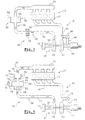
- FIG. 4 represents an advantageous embodiment of the air intake circuit 14 according to the invention.
- the air intake circuit 14 has a portion intermediate 50 which consists of a first section 52 and of a second section 56 which both have a bellows.
- the downstream end 60 of the first section 52 as well as the upstream end 62 of the second section 56 are fixed relative to to the air intake circuit 14. They are for example fixed on an area for fixing the structure of the motor vehicle.
- upstream end 64 of the first section 52 and the downstream end 66 of the second section 56 are linked together by a portion 68 of rigid conduit whose diameter corresponds advantageously to the diameter of the intake duct 26, of so as to form a block 70.
- An actuating cylinder 72 has two ends, one 74 is fixed to the structure of the motor vehicle and the other 76 is linked to block 70.
- the intermediate portion 50 can be integrated so simple in place of a portion of the intake duct 26.
- the length of the intermediate portion 50 is constant. Therefore, the intake duct 26 does not require no flexible portion.
- the upstream end 62 of the second section 56 can be connected directly to the outlet of the air cooling device 28.
- the intermediate portion 50 allows the variation of the volume of the intake duct 26 in a relatively wide range.
- the same intake circuit 14 can be used for different engines including displacement different.
- the intermediate part 50 allows to adapt the resonance frequency of the conduit intake 26 so that the air flowing therein is subjected to a frequency favorable to natural filling of the engine combustion 12.
Landscapes
- Engineering & Computer Science (AREA)
- Chemical & Material Sciences (AREA)
- Combustion & Propulsion (AREA)
- Mechanical Engineering (AREA)
- General Engineering & Computer Science (AREA)
- Supercharger (AREA)
Abstract
Description
- la portion intermédiaire comporte au moins un premier tronçon dont la section est sensiblement égale à la section du conduit d'admission, et la longueur est variable de façon à faire varier la fréquence de résonance du circuit d'admission ;
- la portion intermédiaire comporte au moins un second tronçon dont la section est supérieure à la section du conduit d'admission, et la longueur du second tronçon est variable est variable de façon à faire varier la fréquence de résonance du circuit d'admission ;
- le premier et/ou le second tronçon comporte un soufflet ;
- le premier et/ou le second tronçon comporte un élément télescopique ;
- la longueur d'au moins un tronçon du conduit d'admission est commandée par un actionneur mécanique relié à une extrémité mobile du tronçon correspondant ;
- les longueurs du premier et du second tronçons sont établies simultanément par un actionneur mécanique unique ;
- la longueur totale du conduit d'admission est constante et l'actionneur unique fait varier les longueurs respectives du premier et du second tronçons ;
- le premier tronçon est agencé en aval du second tronçon, par rapport au sens de l'écoulement de l'air dans le conduit d'admission ;
- l'extrémité aval, du premier tronçon et l'extrémité amont du second tronçon sont fixes, et l'extrémité amont du premier tronçon et l'extrémité aval du second tronçon sont liées entre elles ainsi qu'à un actionneur unique de façon que lorsqu'on augmente la longueur du premier tronçon, on diminue d'autant la longueur du second tronçon et inversement ;
- un dispositif de refroidissement d'air est agencé dans le circuit d'admission en aval de la turbine du turbocompresseur et en amont de la portion intermédiaire ;
- l'extrémité amont du second tronçon est raccordée directement à la sortie du dispositif de refroidissement d'air.
- la figure 1 représente schématiquement un moteur à combustion suralimenté par un turbocompresseur et un circuit d'admission réalisé selon l'état de la technique ;
- la figure 2 représente schématiquement un moteur à combustion suralimenté par un turbocompresseur et un circuit d'admission réalisé selon l'invention ;
- les figures 3 et 4 représentent des vues similaires à celle représentée à la figure 2, selon deux autres variantes de réalisation du circuit d'admission selon l'invention.
Claims (12)
- Circuit (14) d'admission d'air d'un moteur (12) suralimenté par un turbocompresseur (18) du type qui comporte un conduit d'admission (26) qui relie le compresseur (22) du turbocompresseur (18) et un répartiteur (34) d'air qui permet de répartir l'air entre les orifices d'admission des chambres de combustion, caractérisé en ce qu'une portion intermédiaire (50) est insérée dans le conduit d'admission (26) et en ce que le volume de la portion intermédiaire est variable de façon à faire varier la fréquence de résonance du circuit (14) d'admission en fonction de la fréquence d'excitation du moteur (12) pour favoriser le remplissage naturel des chambres de combustion du moteur (12).
- Circuit (14) d'admission d'air selon la revendication précédente, caractérisé en ce que la portion intermédiaire (50) comporte au moins un premier tronçon (52) dont la section est sensiblement égale à la section du conduit d'admission (26), et en ce que la longueur est variable de façon à faire varier la fréquence de résonance du circuit (14) d'admission.
- Circuit (14) d'admission d'air selon l'une des revendications 1 ou 2, caractérisé en ce que la portion intermédiaire (50) comporte au moins un second tronçon (56) dont la section est supérieure à la section du conduit d'admission (26), et en ce que la longueur du second tronçon (56) est variable de façon à faire varier la fréquence de résonance du circuit (14) d'admission.
- Circuit (14) d'admission d'air selon l'une des revendications 2 ou 3, caractérisé en ce que le premier (52) et/ou le second tronçon (56) comporte un soufflet (58).
- Circuit (14) d'admission d'air selon l'une quelconque des revendications 2 à 4, caractérisé en ce que le premier (52) et/ou le second tronçon (56) comporte un élément télescopique (54).
- Circuit (14) d'admission d'air selon l'une quelconque des revendications 2 à 5, caractérisé en ce que la longueur d'au moins un tronçon (52, 56) du conduit d'admission est commandée par un actionneur mécanique (57, 74) relié à une extrémité mobile (64, 66) du tronçon correspondant.
- Circuit (14) d'admission d'air selon l'une quelconque des revendications 4 à 6 prise en combinaison avec les revendications 2 et 3, caractérisé en ce que les longueurs du premier et du second tronçons (52, 56) sont établies simultanément par un actionneur mécanique unique (74).
- Circuit (14) d'admission d'air selon la revendication précédente, caractérisé en ce que la longueur totale du conduit d'admission (26) est constante et en ce que l'actionneur unique (74) fait varier les longueurs respectives du premier et du second tronçons (52, 56).
- Circuit (14) d'admission d'air selon la revendication précédente, caractérisé en ce que le premier tronçon (52) est agencé en aval du second tronçon (56), par rapport au sens de l'écoulement de l'air dans le conduit d'admission (26).
- Circuit (14) d'admission d'air selon la revendication précédente, caractérisé en ce que l'extrémité aval (60) du premier tronçon (52) et l'extrémité amont (62) du second tronçon (56) sont fixes, et en ce que l'extrémité amont (64) du premier tronçon (52) et l'extrémité aval (66) du second tronçon (56) sont liées entre elles ainsi qu'à un actionneur unique (74) de façon que lorsqu'on augmente la longueur du premier tronçon (52), on diminue d'autant la longueur du second tronçon (56) et inversement.
- Circuit (14) d'admission d'air selon l'une quelconque des revendications précédentes, caractérisé en ce qu'un dispositif (28) de refroidissement d'air est agencé dans le circuit (14) d'admission en aval de la turbine (24) du turbocompresseur (18) et en amont de la portion intermédiaire (50).
- Circuit (14) d'admission d'air selon la revendication précédente prise en combinaison avec la revendication 9, caractérisé en ce que l'extrémité amont (62) du second tronçon (56) est raccordée directement à la sortie du dispositif (28) de refroidissement d'air.
Applications Claiming Priority (2)
| Application Number | Priority Date | Filing Date | Title |
|---|---|---|---|
| FR0016560A FR2818319B1 (fr) | 2000-12-19 | 2000-12-19 | Circuit d'admission d'air d'un moteur suralimente |
| FR0016560 | 2000-12-19 |
Publications (1)
| Publication Number | Publication Date |
|---|---|
| EP1217187A1 true EP1217187A1 (fr) | 2002-06-26 |
Family
ID=8857847
Family Applications (1)
| Application Number | Title | Priority Date | Filing Date |
|---|---|---|---|
| EP01403247A Withdrawn EP1217187A1 (fr) | 2000-12-19 | 2001-12-14 | Circuit d'admission d'air d'un moteur suralimenté |
Country Status (2)
| Country | Link |
|---|---|
| EP (1) | EP1217187A1 (fr) |
| FR (1) | FR2818319B1 (fr) |
Cited By (6)
| Publication number | Priority date | Publication date | Assignee | Title |
|---|---|---|---|---|
| RU2275517C1 (ru) * | 2004-07-28 | 2006-04-27 | Открытое акционерное общество "Заволжский моторный завод" | Система впуска двигателя внутреннего сгорания |
| FR2877395A1 (fr) | 2004-10-28 | 2006-05-05 | Renault Sas | Moteur comportant un circuit d'admission d'air prevu pour l'optimisation du rendement volumetrique |
| WO2009010151A1 (fr) * | 2007-07-16 | 2009-01-22 | Dr. Ing. H.C. F. Porsche Aktiengesellschaft | Moteur à combustion interne |
| FR2931898A1 (fr) * | 2008-05-28 | 2009-12-04 | Renault Sas | Ligne d'alimentation en air a haute pression d'un moteur a combustion interne suralimente |
| EP2017447A3 (fr) * | 2007-07-16 | 2014-01-22 | Dr. Ing. h.c. F. Porsche AG | Moteur à combustion interne |
| CN110259570A (zh) * | 2019-07-05 | 2019-09-20 | 中国船舶重工集团公司第七0三研究所 | 一种新型可变进气总管谐振进气系统 |
Families Citing this family (3)
| Publication number | Priority date | Publication date | Assignee | Title |
|---|---|---|---|---|
| FR2872856B1 (fr) * | 2004-07-08 | 2009-01-16 | Renault Sas | Dispositif d'admission d'air d'un moteur suralimente |
| CN102767419A (zh) * | 2012-07-03 | 2012-11-07 | 上海交通大学 | 内部带有弹簧的容积腔装置 |
| FR3020092B1 (fr) | 2014-04-16 | 2019-04-05 | Renault S.A.S | Refroidisseur d'air de suralimentation, circuit d'admission d'air et moteur associe suralimente par un turbocompresseur |
Citations (7)
| Publication number | Priority date | Publication date | Assignee | Title |
|---|---|---|---|---|
| DE1009429B (de) * | 1955-06-18 | 1957-05-29 | Daimler Benz Ag | Ansaugleitung fuer Brennkraftmaschinen |
| DE2950667A1 (de) | 1979-11-22 | 1981-06-04 | BBC AG Brown, Boveri & Cie., Baden, Aargau | Verfahren zur dynamischen zusatzaufladung von abgasturboladermotoren und abgasturboladermotor mit mindestens einer einrichtung zur durchfuehrung des verfahrens |
| JPS60104717A (ja) * | 1983-11-11 | 1985-06-10 | Nissan Motor Co Ltd | 過給機付内燃機関 |
| DE3630488A1 (de) * | 1985-09-19 | 1987-03-26 | Volkswagen Ag | Laengenveraenderbares saugrohr fuer eine brennkraftmaschine |
| EP0255059A1 (fr) * | 1986-07-30 | 1988-02-03 | Bayerische Motoren Werke Aktiengesellschaft, Patentabteilung AJ-3 | Collecteur d'admission à résonance pour moteurs à combustion interne |
| JPH02207137A (ja) * | 1989-02-06 | 1990-08-16 | Honda Motor Co Ltd | エンジンの制御装置 |
| DE19622235A1 (de) * | 1996-06-03 | 1997-12-04 | Mann & Hummel Filter | Ansaugvorrichtung für einen Verbrennungsmotor |
-
2000
- 2000-12-19 FR FR0016560A patent/FR2818319B1/fr not_active Expired - Fee Related
-
2001
- 2001-12-14 EP EP01403247A patent/EP1217187A1/fr not_active Withdrawn
Patent Citations (7)
| Publication number | Priority date | Publication date | Assignee | Title |
|---|---|---|---|---|
| DE1009429B (de) * | 1955-06-18 | 1957-05-29 | Daimler Benz Ag | Ansaugleitung fuer Brennkraftmaschinen |
| DE2950667A1 (de) | 1979-11-22 | 1981-06-04 | BBC AG Brown, Boveri & Cie., Baden, Aargau | Verfahren zur dynamischen zusatzaufladung von abgasturboladermotoren und abgasturboladermotor mit mindestens einer einrichtung zur durchfuehrung des verfahrens |
| JPS60104717A (ja) * | 1983-11-11 | 1985-06-10 | Nissan Motor Co Ltd | 過給機付内燃機関 |
| DE3630488A1 (de) * | 1985-09-19 | 1987-03-26 | Volkswagen Ag | Laengenveraenderbares saugrohr fuer eine brennkraftmaschine |
| EP0255059A1 (fr) * | 1986-07-30 | 1988-02-03 | Bayerische Motoren Werke Aktiengesellschaft, Patentabteilung AJ-3 | Collecteur d'admission à résonance pour moteurs à combustion interne |
| JPH02207137A (ja) * | 1989-02-06 | 1990-08-16 | Honda Motor Co Ltd | エンジンの制御装置 |
| DE19622235A1 (de) * | 1996-06-03 | 1997-12-04 | Mann & Hummel Filter | Ansaugvorrichtung für einen Verbrennungsmotor |
Non-Patent Citations (1)
| Title |
|---|
| PATENT ABSTRACTS OF JAPAN vol. 014, no. 501 (M - 1043) 2 November 1990 (1990-11-02) * |
Cited By (11)
| Publication number | Priority date | Publication date | Assignee | Title |
|---|---|---|---|---|
| RU2275517C1 (ru) * | 2004-07-28 | 2006-04-27 | Открытое акционерное общество "Заволжский моторный завод" | Система впуска двигателя внутреннего сгорания |
| FR2877395A1 (fr) | 2004-10-28 | 2006-05-05 | Renault Sas | Moteur comportant un circuit d'admission d'air prevu pour l'optimisation du rendement volumetrique |
| WO2006045986A3 (fr) * | 2004-10-28 | 2006-06-22 | Renault Sa | Moteur comportant un circuit d'admission d'air prevu pour l'optimisation du rendement volumetrique |
| WO2009010151A1 (fr) * | 2007-07-16 | 2009-01-22 | Dr. Ing. H.C. F. Porsche Aktiengesellschaft | Moteur à combustion interne |
| US20100139603A1 (en) * | 2007-07-16 | 2010-06-10 | Dr. Ing. H.C.F. Porsche Aktiengesellschaft | Internal combustion engine |
| RU2445477C2 (ru) * | 2007-07-16 | 2012-03-20 | Др. Инг. Х.Ц.Ф. Порше Акциенгезелльшафт | Двигатель внутреннего сгорания |
| CN101960115B (zh) * | 2007-07-16 | 2013-10-16 | Dr.Ing.h.c.F.保时捷股份公司 | 内燃发动机 |
| EP2017447A3 (fr) * | 2007-07-16 | 2014-01-22 | Dr. Ing. h.c. F. Porsche AG | Moteur à combustion interne |
| US8720402B2 (en) | 2007-07-16 | 2014-05-13 | Dr. Ing. H.C. F. Porsche Aktiengesellschaft | Internal combustion engine |
| FR2931898A1 (fr) * | 2008-05-28 | 2009-12-04 | Renault Sas | Ligne d'alimentation en air a haute pression d'un moteur a combustion interne suralimente |
| CN110259570A (zh) * | 2019-07-05 | 2019-09-20 | 中国船舶重工集团公司第七0三研究所 | 一种新型可变进气总管谐振进气系统 |
Also Published As
| Publication number | Publication date |
|---|---|
| FR2818319B1 (fr) | 2003-06-27 |
| FR2818319A1 (fr) | 2002-06-21 |
Similar Documents
| Publication | Publication Date | Title |
|---|---|---|
| FR2815079A1 (fr) | Moteur a combustion interne avec turbocompresseur a gaz d"echappement et turbine de recuperation compound | |
| EP1217187A1 (fr) | Circuit d'admission d'air d'un moteur suralimenté | |
| FR2644511A1 (fr) | Dispositif d'entrainement compound a turbine pour un moteur a combustion interne | |
| WO2008009789A1 (fr) | Circuit d'alimentation d'un moteur thermique avec mise en rotation des gaz et moteur thermique correspondant | |
| FR3079880A1 (fr) | Module d'admission double flux | |
| FR2957390A1 (fr) | Compresseur de suralimentation a ondes de pression, pour moteurs a combustion interne de vehicules automobiles | |
| WO2009118471A1 (fr) | Moteur a combustion interne a suralimentation pulsee | |
| FR2801072A1 (fr) | Turbocompresseur comportant des entrees de turbine alignees selon un plan radial | |
| EP3132127B1 (fr) | Refroidisseur d'air de suralimentation, circuit d'admission d'air et moteur associe suralimente par un turbocompresseur | |
| FR2875849A1 (fr) | Procede de fonctionnement d'un moteur a combustion interne comprenant un compresseur a ondes de pression | |
| WO2008009790A1 (fr) | Moteur thermique avec circuit de recirculation mixte | |
| FR2534971A1 (fr) | Procede et dispositif de suralimentation d'un moteur a combustion interne par turbocompresseur a gaz d'echappement | |
| FR2904375A1 (fr) | Dispositif pour l'admission d'air en entree d'un compresseur, notamment d'un turbocompresseur | |
| FR2649756A1 (fr) | Dispositif d'echappement perfectionne pour un moteur muni d'un turbocompresseur, notamment pour vehicule automobile | |
| FR2892460A1 (fr) | Systeme d'admission a niveau d'aerodynamique variable a deux turbocompresseurs et procede de commande de perturbation aerodynamique | |
| FR2841601A1 (fr) | Moteur a combustion interne suralimente par un turbocompresseur et equipe d'un circuit d'admission d'air ayant deux modes de vibration de l'air | |
| FR2918709A1 (fr) | Moteur a combustion interne comportant des moyens pour favoriser la recirculation des gaz d'echappement. | |
| FR3087225A1 (fr) | Systeme d'admission d'air equipe d'un moyen de limitation du debit d'air | |
| EP3366902A1 (fr) | Dispositif de contrôle de l'introduction de la quantité de fluide à l'admission d'un moteur à combustion interne suralimenté équipé d'un circuit de recirculation de gaz d'échappement et méthode utilisant un tel dispositif | |
| FR2855212A1 (fr) | Dispositif d'echappement pour moteur a combustion interne et moteur ainsi equipe | |
| FR3159630A1 (fr) | Moteur a combustion interne avec compresseur et refroidisseur a vortex | |
| WO2006045986A2 (fr) | Moteur comportant un circuit d'admission d'air prevu pour l'optimisation du rendement volumetrique | |
| FR2841602A1 (fr) | Moteur a combustion interne muni d'un resonateur de helmholtz integre a un circuit de recirculation des gaz d'echappement qui est connecte a un circuit d'admission d'air | |
| FR2908505A1 (fr) | Echangeur thermique comportant des moyens de purge automatique. | |
| FR2552815A1 (fr) | Turbocompresseur de suralimentation a gaz d'echappement sur moteur a combustion interne suralimente |
Legal Events
| Date | Code | Title | Description |
|---|---|---|---|
| PUAI | Public reference made under article 153(3) epc to a published international application that has entered the european phase |
Free format text: ORIGINAL CODE: 0009012 |
|
| AK | Designated contracting states |
Kind code of ref document: A1 Designated state(s): AT BE CH CY DE DK ES FI FR GB GR IE IT LI LU MC NL PT SE TR |
|
| AX | Request for extension of the european patent |
Free format text: AL;LT;LV;MK;RO;SI |
|
| RAP1 | Party data changed (applicant data changed or rights of an application transferred) |
Owner name: RENAULT S.A.S. |
|
| AKX | Designation fees paid | ||
| 17P | Request for examination filed |
Effective date: 20021205 |
|
| RBV | Designated contracting states (corrected) |
Designated state(s): BE DE ES |
|
| REG | Reference to a national code |
Ref country code: DE Ref legal event code: 8566 |
|
| 17Q | First examination report despatched |
Effective date: 20061108 |
|
| 17Q | First examination report despatched |
Effective date: 20061108 |
|
| GRAP | Despatch of communication of intention to grant a patent |
Free format text: ORIGINAL CODE: EPIDOSNIGR1 |
|
| STAA | Information on the status of an ep patent application or granted ep patent |
Free format text: STATUS: THE APPLICATION IS DEEMED TO BE WITHDRAWN |
|
| 18D | Application deemed to be withdrawn |
Effective date: 20080930 |