EP1218268B1 - Spannanordnungsvorrichtung für förderbandreiniger - Google Patents
Spannanordnungsvorrichtung für förderbandreiniger Download PDFInfo
- Publication number
- EP1218268B1 EP1218268B1 EP00967434A EP00967434A EP1218268B1 EP 1218268 B1 EP1218268 B1 EP 1218268B1 EP 00967434 A EP00967434 A EP 00967434A EP 00967434 A EP00967434 A EP 00967434A EP 1218268 B1 EP1218268 B1 EP 1218268B1
- Authority
- EP
- European Patent Office
- Prior art keywords
- conveyor belt
- shaft
- cleaning apparatus
- arms
- scraping blade
- Prior art date
- Legal status (The legal status is an assumption and is not a legal conclusion. Google has not performed a legal analysis and makes no representation as to the accuracy of the status listed.)
- Expired - Lifetime
Links
- 238000007790 scraping Methods 0.000 claims abstract description 41
- 238000004140 cleaning Methods 0.000 claims abstract description 24
- 238000000429 assembly Methods 0.000 claims description 7
- 230000000712 assembly Effects 0.000 claims description 5
- 239000000463 material Substances 0.000 claims description 5
- 239000013598 vector Substances 0.000 description 4
- 239000003245 coal Substances 0.000 description 3
- 230000007246 mechanism Effects 0.000 description 2
- 239000011236 particulate material Substances 0.000 description 2
- 230000036316 preload Effects 0.000 description 2
- XLYOFNOQVPJJNP-UHFFFAOYSA-N water Substances O XLYOFNOQVPJJNP-UHFFFAOYSA-N 0.000 description 2
- 239000004743 Polypropylene Substances 0.000 description 1
- 229910000831 Steel Inorganic materials 0.000 description 1
- 239000000428 dust Substances 0.000 description 1
- 229920001971 elastomer Polymers 0.000 description 1
- 239000008187 granular material Substances 0.000 description 1
- 229910052500 inorganic mineral Inorganic materials 0.000 description 1
- 238000011068 loading method Methods 0.000 description 1
- 238000012423 maintenance Methods 0.000 description 1
- 238000000034 method Methods 0.000 description 1
- 239000011707 mineral Substances 0.000 description 1
- 238000005065 mining Methods 0.000 description 1
- 239000004033 plastic Substances 0.000 description 1
- 229920003023 plastic Polymers 0.000 description 1
- -1 polypropylene Polymers 0.000 description 1
- 229920001155 polypropylene Polymers 0.000 description 1
- 229920002635 polyurethane Polymers 0.000 description 1
- 239000004814 polyurethane Substances 0.000 description 1
- 230000002028 premature Effects 0.000 description 1
- 239000002002 slurry Substances 0.000 description 1
- 239000007779 soft material Substances 0.000 description 1
- 239000010959 steel Substances 0.000 description 1
Images


Classifications
-
- B—PERFORMING OPERATIONS; TRANSPORTING
- B65—CONVEYING; PACKING; STORING; HANDLING THIN OR FILAMENTARY MATERIAL
- B65G—TRANSPORT OR STORAGE DEVICES, e.g. CONVEYORS FOR LOADING OR TIPPING, SHOP CONVEYOR SYSTEMS OR PNEUMATIC TUBE CONVEYORS
- B65G45/00—Lubricating, cleaning, or clearing devices
- B65G45/10—Cleaning devices
- B65G45/12—Cleaning devices comprising scrapers
- B65G45/16—Cleaning devices comprising scrapers with scraper biasing means
Definitions
- the present invention relates generally to belt conveyors, and more particularly to a conveyor belt cleaning apparatus for use with such conveyors.
- Belt conveyors are used in a variety of applications for the transportation of particulate or granular material, such as coal, grain, ore, minerals, and the like.
- a known seraping device can be seen in US-A-4 664 250, for example.
- scraping devices have several inherent disadvantages. The most significant of these relates to the need for the scrapers to accommodate surface irregularities in the belt. Such irregularities most commonly take the form of belt fasteners, which are typically formed from steel and protrude beyond the surface of the belt. These fasteners can cause hardened scraping blades to break, chip or shatter, leading to reduced scraping efficiency and downtime whilst repair operations take place. This can also cause premature failure of the belt fasteners.
- scraping blades have been formed from relatively soft materials such as polyurethane, polypropylene and other plastics. Whilst being better able to accommodate surface irregularities in the belt without breakage, such blades are prone to rapid abrasive wear, and hence require frequent replacement. This is costly, and again often results in undesirable downtime.
- a further problem with known scraping devices relates to the need for each of several scraping blades to be individually adjusted to the correct position relative to the belt, and relative to the adjacent blades. This set-up procedure is time consuming, labour intensive and expensive. Moreover, frequent recalibration is normally required in order to accommodate wear of the scraping blades.
- a conveyor belt cleaning apparatus for a belt conveyor comprising:
- the scraping blade In use the scraping blade is maintained in a plane substantially perpendicular to the plane of the conveyor belt surface.
- the axis of the shaft is substantially transverse to the direction of movement of the conveyor belt.
- the mountings of the first and second arms each include a resilient element configured to urge the scraping blade into operative scraping engagement with the conveyor belt surface.
- the resilient element comprises a torsion spring.
- the resilient element is formed from a resiliently deformable material.
- the mountings are adjustable so as to produce the desired contact pressure between the scraping blade and the conveyor belt surface.
- the mountings of the first and second arms each include a pair of collars comprising a first collar which is rotatably mounted on the shaft and to which a respective arm is connected and a second collar adapted to be locked in position on the shaft, a torsion spring being interposed between the first and second collars with free ends of the torsion spring engaging with the first and second collars, wherein by rotatably adjusting the relative position of the first and second collars on the shaft it is possible to adjust the spring tension in the torsion spring and the biasing torque imposed on the arms connected to each end of the scraping blade.
- each mounting assembly further includes a locking collar through which the shaft passes and which is locked in position on the shaft, a mounting block, and a torsion spring interposed between the locking collar and the mounting block, with one free end of the torsion spring being engaged in the locking collar and a second free end being engaged in the mounting block so as to provide a torque on the shaft.
- the third arm comprises a first link and a second link which are pivotably connected together at a hinge point, the first link being connected to the shaft and the second link being connected to the scraping blade.
- the second link is adjustable in length by means of a threaded shaft and nut arrangement.
- the conveyor belt cleaning apparatus is adapted to be positioned on the underside of the conveyor belt so as to clean the carrying surface of the conveyor belt as it returns from its discharge point.
- the present invention provides a conveyor belt cleaning apparatus for positioning a scraping blade against the surface of a conveyor belt and which is designed to maintain a relatively uniform blade pressure across substantially the full width of the blade, whilst maintaining the blade in a plane substantially perpendicular to the plane of the conveyor belt surface.
- the present invention has particular application with a curved scraping blade, although the invention may be adapted for use with a straight (also known as "inline") scraping blade.
- a straight scraping blade also known as "inline” scraping blade.
- belt cleaners which employ a curved blade use an adjustment mechanism which produces an arced motion so as to bring the cleaner blade into contact with the conveyor belt. This results in a non-uniform pressure across the width of the blade, with greater pressure being applied around the mid point of the cleaner blade.
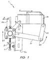
- the present invention provides a conveyor belt cleaning apparatus 1 for use with a conveyor comprising an endless flexible belt extending between head pulleys (not shown).
- a conveyor comprising an endless flexible belt extending between head pulleys (not shown).
- head pulleys, intermediate rollers, drive mechanisms and associated support structures of conventional belt conveyor assemblies are well known to those skilled in the art, and so will not be described in further detail.
- the conveyor belt cleaner I includes a shaft 2 which, in use, is mounted on the conveyor structure so as to extend transversely across the width of the conveyor. At each end of the shaft 2 there is provided a mounting sub-assembly 3a, 3b in order to mount the belt cleaner to the frame of the conveyor (not shown).
- the belt cleaner assembly is mounted on the underside (commonly referred to as the "return side") of the conveyor belt so as to clean the carrying surface of the conveyor belt as it returns from its discharge point.
- the direction of motion of the conveyor belt is indicated by the arrow X.
- the mounting sub-assemblies 3a, 3b include bearings 4a, 4b within which respective ends of the shaft 2 are rotatably mounted.
- the bearings 4a, 4b are each mounted on mounting plates 5a, 5b of the respective mounting sub-assemblies 3a, 3b.
- Each mounting sub-assembly 3a, 3b further includes a respective adjustment means 6a, 6b at each end of the shaft 2 in the form of a threaded bolt and nut arrangement 7, 8 so as to provide for adjustment of the position of the shaft 2 relative to the plane of the conveyor belt.
- the adjustment means 6a, 6b provides for the movement of each end of the shaft 2 in a substantially vertical plane as illustrated by arrow A in Fig. 1.
- each arm 10a, 10b is connected to a tensioning means (not shown) in the form of a spring, pneumatic or hydraulic ram, or the like which applies a tension force to the arm in the direction indicated by the arrow B in Fig. 1.
- This force is transmitted via the arms 10a, 10b to provide a torque (indicated by the arrow T in Fig. 2) to the shaft 2 and bring scraping blade 30 into contact with the carrying surface of the conveyor belt.
- a pre-load force is applied to the scraping blade 30 which allows the blade to follow the surface of the belt as it moves during operation.
- the belt cleaner assembly further includes a pair of arms 20a, 20b, which are mounted on the main shaft 2.
- the arms 20a, 20b are pivotably connected to respective ends of a curved cleaner blade 30 so as to support the cleaner blade at its ends and provide a relatively uniform and controlled contact pressure between the blade and the conveyor belt surface across the full width of the blade.
- the mountings 21a, 21b of the arms 20a, 20b on the shaft 2 are adapted to provide for independent tensioning so as to allow each arm to move independent of the other and thereby allow for any belt movement.
- Each mounting 21a, 21b on the shaft includes a resilient biasing means (not shown) which permits a degree of biased rotation for each arm with respect to the axis of the shaft 2 and which, in use, acts to bias the respective arms 20a, 20b towards the conveyor belt.
- the mountings 21 a, 21 b preferably include a resiliently deformable material, such as rubber, which acts to resiliently bias the respective arms 20a, 20b towards the conveyor belt.
- other forms of biasing may be employed, such as springs for example.
- the assembly further includes a supporting arm arrangement 40 located intermediate the end arms 20a, 20b.
- the intermediate arm 40 is located mid-way between the end arms 20a, 20b.
- the intermediate arm arrangement 40 assists in keeping a uniform pressure on the blade over the full width of the blade.
- the linkage comprises an arm 41 which is connected at one end to the shaft 2 and is pivotably connected to arm 42 at hinge point 43.
- the supporting arm 40 acts to maintain the cleaner blade substantially perpendicular to the surface of the conveyor belt.
- FIGs. 3 to 10 a second preferred embodiment of the present invention is depicted.
- those components which are shared with the embodiment depicted in Figs. 1 and 2 are provided with identical reference numerals.
- the mounting sub-assembly 3a, 3b for each end of the shaft 2 includes a mounting bush 51a, 51b within which the shaft 2 is rotatably mounted.
- Each mounting bush 51a, 51b is held in a respective mounting block 52a, 52b which is attached to mounting plate 5a, 5b.
- the mounting plates 5a, 5b are each provided with an elongated slot 11 through which bolts 12 pass so as to secure the mounting block to the mounting plate.
- Each mounting sub-assembly includes a respective adjustment means 6a, 6b at each end of the shaft 2 in the form of a threaded bolt 7 and nut 8 arrangement so as to provide for adjustment of the position of the shaft 2 relative to the plane of the conveyor belt as previously described with reference to the embodiment of Figs. I and 2.
- the bolts 12 are tightened to secure the mounting block in position on the mounting plate.
- Each mounting sub-assembly further includes a pair of inner and outer torsion springs and collars which are mounted on the shaft 2 and which are configured to impart the desired loadings upon the cleaner blade 30.
- each end of the cleaner blade is pivotably connected to an arm 20a, 20b.
- the arms 20a, 20b are connected to a pair of first collars 53a, 53b which are rotatably mounted on respective ends of the shaft 2.
- a pair of second collars 54a, 54b are rotatably mounted on respective ends the shaft but can be locked in position on the shaft 2 by means of locking screws/bolts 55.
- a pair of first torsion springs 56a, 56b are interposed between each pair of adjacent first and second collars with the free ends of the torsion spring engaging in the collars.
- Each mounting sub-assembly further includes an outer locking collar 57a, 57b through which the shaft 2 passes and which can be locked in position on the shaft by means of locking screws/bolts 58.
- a second torsion spring 59a, 59b is interposed between each outer locking collar 57a, 57b and its respective mounting block 52a, 52b, with one free end 60a, 60b of the torsion spring being engaged in the respective collar 57a, 57b and the second free end 61a, 61b being respectively engaged in the mounting block 52a, 52b.
- the assembly further includes a supporting arm arrangement 10 located intermediate the end arms 20a, 20b.
- the intermediate arm 40 is located midway between the end arms 20a, 20b.
- the linkage comprises an arm 41 which is connected at one end to the shaft 2 and is pivotally connected to arm 42 at hinge point 43.
- the arm 42 is adjustable in length by means of a threaded shaft and nut arrangement.
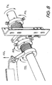
- FIGs. 8 to 10 typical force and torque vectors imposed on the cleaner assembly when in use are illustrated.
- the shaft 2 is free to rotate in the mounting bushes 51a, 51b and is attached to the cleaner blade 30 by means of the outer arms 20a, 20b and the intermediate arm 40.
- the outer torsion spring 59a, 59b on each end of the shaft has one free end engaged in its adjacent mounting block 52a, 52b and its other free end engaged in its respective outer torsion collar 57a, 57b.
- the outer torsion springs are supplied in sets of two, with one being wound left hand and the other right hand.
- the outer torsion collar on each end of the shaft provides a torque to the shaft 2 which acts against the shaft's tendency to rotate away from the conveyor belt when under load. This provides an upward force "FC” acting at the cleaner's blade centre (see Fig. 10).
- Adjustment of the magnitude of the force "FC” is achieved by holding the shaft stationary, loosening the locking bolts in the torsion collar, rotating the torsion collar in the direction of "A1L” and “A1R” respectively until the desired pre-load is achieved and then tightening the locking bolts to secure the torsion collar in the new position.
- the cleaner blade connecting arms 20a, 20b provide the forces “F2L” and “F2R” at each end of the cleaner blade via the inner torsion springs.
- the forces “F2L” and “F2R” are increased by adjusting the inner torsion collars position on the shaft in the direction indicated by “A2L” and “A2R”.
- the forces “F2L” and “F2R” act independently of each other and thus provide the even distribution of cleaner blade pressure on the belt while allowing the blade to follow any variations in the plane of the conveyor belt.
- the assembly of the present invention provides for a belt cleaner assembly which provides a relatively uniform pressure across the full width of the cleaner blade whilst enabling a full adjustable inline tensioning device.
Landscapes
- Engineering & Computer Science (AREA)
- Mechanical Engineering (AREA)
- Structure Of Belt Conveyors (AREA)
- Cleaning In General (AREA)
- Paper (AREA)
- Devices For Conveying Motion By Means Of Endless Flexible Members (AREA)
- Preliminary Treatment Of Fibers (AREA)
Claims (13)
- Förderband-Reinigungsvorrichtung (1) für ein Förderband, wobei die Reinigungsvorrichtung umfasst:wobei die Vorrichtung weiterhin einen dritten Arm (40) umfasst, der auf der Welle angebracht ist und zwischen den ersten und zweiten Armen zum Stützen der Kratzklinge angeordnet ist,eine Welle (2)ein Paar von Einfassungsanordnungen (3a, 36) zum Einfassen der Welle an einem Rahmen des Förderbands, wobei die Welle rotierbar in den Einfassungsanordnungen angebracht ist,einen ersten Arm (20a) und einen zweiten Arm (20b) zum Halten einer Kratzklinge (30), wobei erste und zweite Arme unabhängig an der Welle und unabhängig rotierbar um die Achse der Welle angebracht sind, die Einfassungen (21a, 21b) der ersten und zweiten Arme ausgelegt sind, um die jeweiligen Arme zu der Förderbandoberfläche hin zu spannen,
so dass die Rotation der Arme um die Achse der Welle in Positionierungseinstellungen der Kratzklinge (30) in Bezug auf die Förderbandoberfläche resultiert, wobei die Arme schwenkbar mit der Kratzklinge verbunden sind, um einen relativ gleichförmigen Kontaktdruck zwischen der Klinge und der Förderbandoberfläche über die Breite der Klinge hinweg zu ergeben. - Förderband-Reinigungsvorrichtung nach Anspruch 1, worin bei Gebrauch die Kratzklinge (30) in einer Ebene im Wesentlichen senkrecht zur Ebene der Förderbandoberfläche gehalten wird.
- Förderband-Reinigungsvorrichtung nach Anspruch 1, worin, wenn an dem Rahmen des Förderbands angebracht, die Achse der Welle im Wesentlichen quer zur Bewegungsrichtung des Förderbands ist.
- Förderband-Reinigungsvorrichtung nach Anspruch 1, worin die Einfassungen (21a, 21b) der ersten und zweiten Arme (20a, 20b) jede ein elastisches Element einschließen, das konfiguriert ist, um die Kratzklinge in kratzend wirkenden Eingriff mit der Förderbandoberfläche zu bringen.
- Förderband-Reinigungsvorrichtung nach Anspruch 4, worin das elastische Element eine Torsionsfeder (56a, 56b) umfasst.
- Förderband-Reinigungsvorrichtung nach Anspruch 4, worin das elastische Element gebildet ist aus elastisch verformbarem Material.
- Förderband-Reinigungsvorrichtung nach Anspruch 4, worin die Einfassungen (21a, 21b) so einstellbar sind, dass sie den gewünschten Kontaktdruck zwischen der Kratzklinge und der Förderbandoberfläche erzeugen.
- Förderband-Reinigungsvorrichtung nach Anspruch 7, worin die Einfassungen der ersten und zweiten Arme jede ein Paar von Kragen (53a, 53b) einschließen, umfassend einen ersten Kragen, der rotierbar auf der Welle angebracht ist und mit dem ein jeweiliger Arm verbunden ist und einen zweiten Kragen (54a, 54b) ausgelegt, um in Position an der Welle gesperrt zu werden, wobei die Torsionsfeder (56a, 56b) zwischen die ersten und zweiten Kragen mit freien Enden der Torsionsfeder in Eingriff mit dem ersten und zweiten Kragen zwischengesetzt ist, wobei durch rotierendes Einstellen der relativen Position der ersten und zweiten Kragen an der Welle es möglich ist, die Federspannung der Torsionsfeder und das Federdrehmoment, welches auf die mit jedem Ende der Kratzklinge verbundenen Arme auferlegt wird, einzustellen.
- Förderband-Reinigungsvorrichtung nach einem der Ansprüche 1 bis 8, worin jede Einfassungsanordnung weiterhin einen Sperrkragen (57a, 57b) umfasst, durch welchen die Welle läuft und welcher in Position an der Welle gesperrt ist, einen Einfassungsblock und eine Torsionsfeder (59a, 59b), zwischengesetzt zwischen dem Sperrkragen und dem Einfassungsblock mit einem freien Ende der Torsionsfeder in Eingriff in dem Sperrkragen und einem zweiten freien Ende in Eingriff mit dem Anbringungsblock, um ein Drehmoment auf die Welle auszuüben.
- Förderband-Reinigungsvorrichtung nach einem der Ansprüche 1 bis 9, worin der dritte Arm (40) eine erste Verbindung (41) und eine zweite Verbindung (42) umfasst, welche schwenkbar miteinander an einem Scharnierpunkt (43) verbunden sind, wobei die erste Verbindung mit der Welle verbunden ist und die zweite Verbindung mit der Kratzklinge (30) verbunden ist.
- Förderband-Reinigungsvorrichtung nach Anspruch 10, worin die zweite Verbindung mittels einer Welle- und Mutteranordnung mit Gewinde in der Länge einstellbar ist.
- Förderband-Reinigungsvorrichtung nach einem der Ansprüche 1 bis 11 und ausgelegt, um an der Unterseite des Förderbands angeordnet zu werden, um die Tragoberfläche des Förderbands zu reinigen, wenn es von seinem Entladungspunkt zurückkehrt.
- Förderband-Reinigungsvorrichtung nach einem der Ansprüche 1 bis 12, worin die Kratzklinge (30) von einem gebogenem Typ ist.
Applications Claiming Priority (5)
| Application Number | Priority Date | Filing Date | Title |
|---|---|---|---|
| AUPQ3116A AUPQ311699A0 (en) | 1999-09-27 | 1999-09-27 | Conveyor belt cleaner tensioning device |
| AUPQ311699 | 1999-09-27 | ||
| AUPQ7388A AUPQ738800A0 (en) | 2000-05-09 | 2000-05-09 | Conveyor belt cleaning apparatus |
| AUPQ738800 | 2000-05-09 | ||
| PCT/AU2000/001175 WO2001023284A1 (en) | 1999-09-27 | 2000-09-27 | Conveyor belt cleaner tensioning device |
Publications (3)
| Publication Number | Publication Date |
|---|---|
| EP1218268A1 EP1218268A1 (de) | 2002-07-03 |
| EP1218268A4 EP1218268A4 (de) | 2003-04-02 |
| EP1218268B1 true EP1218268B1 (de) | 2004-12-22 |
Family
ID=25646159
Family Applications (1)
| Application Number | Title | Priority Date | Filing Date |
|---|---|---|---|
| EP00967434A Expired - Lifetime EP1218268B1 (de) | 1999-09-27 | 2000-09-27 | Spannanordnungsvorrichtung für förderbandreiniger |
Country Status (8)
| Country | Link |
|---|---|
| US (1) | US6820734B1 (de) |
| EP (1) | EP1218268B1 (de) |
| AT (1) | ATE285372T1 (de) |
| CA (1) | CA2385687C (de) |
| DE (1) | DE60016942T2 (de) |
| ES (1) | ES2233458T3 (de) |
| NZ (1) | NZ518313A (de) |
| WO (1) | WO2001023284A1 (de) |
Families Citing this family (25)
| Publication number | Priority date | Publication date | Assignee | Title |
|---|---|---|---|---|
| CA2439047A1 (en) * | 2001-02-22 | 2002-09-06 | John Hall | Conveyor belt cleaning system |
| US7073661B2 (en) | 2004-03-04 | 2006-07-11 | Tennant | Self cleaning conveyor with roller scraper and debris reduction skirt |
| US7367443B2 (en) * | 2004-11-24 | 2008-05-06 | Martin Engineering Company | Conveyor belt cleaner system and method of manufacturing same |
| US7584835B2 (en) * | 2005-03-11 | 2009-09-08 | Asgco Manufacturing, Inc. | Adjustable V-plow apparatus for deflecting material carried on a belt |
| US7669708B2 (en) * | 2006-08-31 | 2010-03-02 | Martin Engineering Company | Bulk material handling system and control |
| US7556140B2 (en) | 2006-08-31 | 2009-07-07 | Martin Engineering Company | Bulk material handling system |
| DE202007011727U1 (de) * | 2007-08-22 | 2007-10-25 | Schulmeistrat, Hans-Dieter | Förderbandabstreifer mit einer parabolartig geformten Abstreiferleiste |
| US8061508B2 (en) * | 2007-10-09 | 2011-11-22 | William Metzner | Secondary conveyor belt cleaner and mounting system therefor |
| JP4801753B2 (ja) * | 2009-03-02 | 2011-10-26 | 日本通商株式会社 | ベルトクリーナ装置 |
| US8205741B2 (en) | 2010-08-06 | 2012-06-26 | Martin Engineering Company | Method of adjusting conveyor belt scrapers and open loop control system for conveyor belt scrapers |
| BR112014016034A8 (pt) * | 2012-01-09 | 2017-07-04 | Tega Ind Ltd | engaste de raspador de correia aperfeiçoado |
| US8776990B2 (en) * | 2012-01-24 | 2014-07-15 | Superior Industries, Inc. | Dual belt cleaner |
| CA2872767C (en) * | 2012-05-08 | 2020-08-04 | Asgco Manufacturing, Inc. | Flip-able v-plow belt cleaner |
| CN104428223B (zh) * | 2012-06-26 | 2016-06-29 | 泰加工业有限公司 | 输送带刮刀组件 |
| BE1021397B1 (fr) * | 2013-07-22 | 2015-11-16 | Technic Gum International Sprl | Dispositif de raclage |
| DE202014007229U1 (de) | 2014-08-11 | 2015-07-01 | F.E. Schulte Strathaus GmbH & Co. KG Fördertechnik Dichtungssysteme | Förderband-Abstreifvorrichtung |
| US9469484B2 (en) * | 2014-12-12 | 2016-10-18 | Tega Industries Limited | Belt scraper assembly |
| US9376264B1 (en) | 2014-12-17 | 2016-06-28 | Shawn Michael Foley | Conveyor belt cleaning apparatus |
| CN105947601A (zh) * | 2016-06-21 | 2016-09-21 | 天津振兴水泥有限公司 | 一种输送胶带机尾部清扫装置 |
| US9738456B1 (en) | 2016-08-02 | 2017-08-22 | Superior Industries, Inc. | Conveyor belt cleaner |
| US10046920B1 (en) * | 2017-05-15 | 2018-08-14 | Sanitec Green LLC | System and methods for automated sanitation of conveyer belts |
| FI128605B (en) * | 2018-06-05 | 2020-08-31 | Marko Lindeman | Device for cleaning ribbons in a bowling machine |
| CN110104409A (zh) * | 2019-05-29 | 2019-08-09 | 贵州开磷有限责任公司 | 一种多刀片自调式清扫器 |
| BR112022013393A2 (pt) * | 2020-01-06 | 2022-09-13 | Australian Conveyor Components Pty Ltd | Aparelho de limpeza de correia transportadora |
| CA3185471A1 (en) | 2021-12-09 | 2023-06-09 | Superior Industries, Inc. | Conveyor scraper systems, methods and apparatus |
Family Cites Families (10)
| Publication number | Priority date | Publication date | Assignee | Title |
|---|---|---|---|---|
| GB1420439A (en) * | 1972-12-07 | 1976-01-07 | Ward C W | Conveyor belt cleaning apparatus |
| US4352425A (en) * | 1981-04-22 | 1982-10-05 | Ray Childress | Belt cleaner |
| US4402394A (en) | 1981-07-27 | 1983-09-06 | Stoll Donald L | Conveyor belt scraper |
| DE3410046A1 (de) | 1984-03-19 | 1985-09-26 | Jakobs, Hartmut, Dipl.-Kaufm., 4350 Recklinghausen | Abstreifvorrichtung fuer foerderbaender |
| JPS6464915A (en) * | 1987-05-07 | 1989-03-10 | Nihon Tsusho Kk | Belt cleaner |
| GB8903217D0 (en) * | 1989-02-13 | 1989-03-30 | Doncaster Conveyor Improv | Conveyor belt scraper mechanism |
| GB2222132B (en) * | 1989-04-28 | 1991-10-02 | Jobel Eng Ltd | An improved conveyor belt scraper |
| US4969553A (en) * | 1990-02-08 | 1990-11-13 | Richwood Industries, Inc. | Belt scraper with gear adjustment |
| US5248026A (en) * | 1992-07-22 | 1993-09-28 | Morefield Allen J | Conveyor belt scraper mechanisms |
| US6152290A (en) * | 1997-09-26 | 2000-11-28 | Asgco Manufacturing, Inc. | Cleaning device for conveyor belt assembly |
-
2000
- 2000-09-27 CA CA002385687A patent/CA2385687C/en not_active Expired - Fee Related
- 2000-09-27 WO PCT/AU2000/001175 patent/WO2001023284A1/en not_active Ceased
- 2000-09-27 EP EP00967434A patent/EP1218268B1/de not_active Expired - Lifetime
- 2000-09-27 US US10/089,283 patent/US6820734B1/en not_active Expired - Fee Related
- 2000-09-27 NZ NZ518313A patent/NZ518313A/xx unknown
- 2000-09-27 DE DE60016942T patent/DE60016942T2/de not_active Expired - Fee Related
- 2000-09-27 AT AT00967434T patent/ATE285372T1/de not_active IP Right Cessation
- 2000-09-27 ES ES00967434T patent/ES2233458T3/es not_active Expired - Lifetime
Also Published As
| Publication number | Publication date |
|---|---|
| DE60016942T2 (de) | 2005-12-22 |
| ES2233458T3 (es) | 2005-06-16 |
| US6820734B1 (en) | 2004-11-23 |
| NZ518313A (en) | 2003-02-28 |
| ATE285372T1 (de) | 2005-01-15 |
| WO2001023284A1 (en) | 2001-04-05 |
| CA2385687C (en) | 2008-11-04 |
| DE60016942D1 (de) | 2005-01-27 |
| CA2385687A1 (en) | 2001-04-05 |
| EP1218268A4 (de) | 2003-04-02 |
| EP1218268A1 (de) | 2002-07-03 |
Similar Documents
| Publication | Publication Date | Title |
|---|---|---|
| EP1218268B1 (de) | Spannanordnungsvorrichtung für förderbandreiniger | |
| US6360875B1 (en) | Conveyor belt scraper tensioner | |
| US6152290A (en) | Cleaning device for conveyor belt assembly | |
| US6575292B2 (en) | Conveyor belt cleaner and tensioner assembly | |
| RU2276654C2 (ru) | Направляющее устройство для конвейерной ленты | |
| US7093706B2 (en) | Conveyor belt cleaning system | |
| US5339947A (en) | Scraping device for belt conveyors | |
| AU2003279295B2 (en) | Conveyor belt cleaning system | |
| EP1196340B1 (de) | Spannvorrichtung für einen förderbandabstreicher | |
| CA2179033C (en) | Cleaning device for endless conveyor | |
| US5161666A (en) | Conveyor belt cleaner | |
| CA1225354A (en) | Belt trainer apparatus for a conveyor | |
| AU760781B2 (en) | Conveyor belt cleaner tensioning device | |
| US4958719A (en) | Apparatus for scraping solid materials from a conveyor surface | |
| US5065859A (en) | Conveyor belt scraper | |
| CN220484500U (zh) | 传送带清扫装置 | |
| EP1036749B1 (de) | Förderbandreiniger und -spannvorrichtung | |
| EP0869090A2 (de) | Abstreifvorrichtung zum Reinigen von Förderern | |
| CN220033080U (zh) | 输送机及破碎站 | |
| JPH10147419A (ja) | ベルトコンベアのスクレーパ装置 | |
| EP0099356A1 (de) | Förderbandreiniger | |
| AU697319B2 (en) | Scraping assembly for belt conveyors | |
| SU1034967A1 (ru) | Устройство дл очистки конвейерной ленты | |
| CN112607367A (zh) | 一种补偿机构及带式输送机清扫器 | |
| MXPA00000481A (es) | Aspa raspadora para banda transportadora de desgaste diferencial |
Legal Events
| Date | Code | Title | Description |
|---|---|---|---|
| PUAI | Public reference made under article 153(3) epc to a published international application that has entered the european phase |
Free format text: ORIGINAL CODE: 0009012 |
|
| 17P | Request for examination filed |
Effective date: 20020403 |
|
| AK | Designated contracting states |
Kind code of ref document: A1 Designated state(s): AT BE CH CY DE DK ES FI FR GB GR IE IT LI LU MC NL PT SE |
|
| AX | Request for extension of the european patent |
Free format text: AL;LT;LV;MK;RO;SI |
|
| RIN1 | Information on inventor provided before grant (corrected) |
Inventor name: RUDD, KEVIN Inventor name: GILBERT, ROBERT, PATRICK |
|
| A4 | Supplementary search report drawn up and despatched |
Effective date: 20030220 |
|
| GRAP | Despatch of communication of intention to grant a patent |
Free format text: ORIGINAL CODE: EPIDOSNIGR1 |
|
| GRAS | Grant fee paid |
Free format text: ORIGINAL CODE: EPIDOSNIGR3 |
|
| GRAA | (expected) grant |
Free format text: ORIGINAL CODE: 0009210 |
|
| AK | Designated contracting states |
Kind code of ref document: B1 Designated state(s): AT BE CH CY DE DK ES FI FR GB GR IE IT LI LU MC NL PT SE |
|
| PG25 | Lapsed in a contracting state [announced via postgrant information from national office to epo] |
Ref country code: IT Free format text: LAPSE BECAUSE OF FAILURE TO SUBMIT A TRANSLATION OF THE DESCRIPTION OR TO PAY THE FEE WITHIN THE PRESCRIBED TIME-LIMIT;WARNING: LAPSES OF ITALIAN PATENTS WITH EFFECTIVE DATE BEFORE 2007 MAY HAVE OCCURRED AT ANY TIME BEFORE 2007. THE CORRECT EFFECTIVE DATE MAY BE DIFFERENT FROM THE ONE RECORDED. Effective date: 20041222 Ref country code: LI Free format text: LAPSE BECAUSE OF FAILURE TO SUBMIT A TRANSLATION OF THE DESCRIPTION OR TO PAY THE FEE WITHIN THE PRESCRIBED TIME-LIMIT Effective date: 20041222 Ref country code: AT Free format text: LAPSE BECAUSE OF FAILURE TO SUBMIT A TRANSLATION OF THE DESCRIPTION OR TO PAY THE FEE WITHIN THE PRESCRIBED TIME-LIMIT Effective date: 20041222 Ref country code: CH Free format text: LAPSE BECAUSE OF FAILURE TO SUBMIT A TRANSLATION OF THE DESCRIPTION OR TO PAY THE FEE WITHIN THE PRESCRIBED TIME-LIMIT Effective date: 20041222 Ref country code: FI Free format text: LAPSE BECAUSE OF FAILURE TO SUBMIT A TRANSLATION OF THE DESCRIPTION OR TO PAY THE FEE WITHIN THE PRESCRIBED TIME-LIMIT Effective date: 20041222 Ref country code: BE Free format text: LAPSE BECAUSE OF FAILURE TO SUBMIT A TRANSLATION OF THE DESCRIPTION OR TO PAY THE FEE WITHIN THE PRESCRIBED TIME-LIMIT Effective date: 20041222 |
|
| REG | Reference to a national code |
Ref country code: GB Ref legal event code: FG4D |
|
| REG | Reference to a national code |
Ref country code: CH Ref legal event code: EP |
|
| REG | Reference to a national code |
Ref country code: IE Ref legal event code: FG4D |
|
| REF | Corresponds to: |
Ref document number: 60016942 Country of ref document: DE Date of ref document: 20050127 Kind code of ref document: P |
|
| PG25 | Lapsed in a contracting state [announced via postgrant information from national office to epo] |
Ref country code: DK Free format text: LAPSE BECAUSE OF FAILURE TO SUBMIT A TRANSLATION OF THE DESCRIPTION OR TO PAY THE FEE WITHIN THE PRESCRIBED TIME-LIMIT Effective date: 20050322 Ref country code: SE Free format text: LAPSE BECAUSE OF FAILURE TO SUBMIT A TRANSLATION OF THE DESCRIPTION OR TO PAY THE FEE WITHIN THE PRESCRIBED TIME-LIMIT Effective date: 20050322 Ref country code: GR Free format text: LAPSE BECAUSE OF FAILURE TO SUBMIT A TRANSLATION OF THE DESCRIPTION OR TO PAY THE FEE WITHIN THE PRESCRIBED TIME-LIMIT Effective date: 20050322 |
|
| REG | Reference to a national code |
Ref country code: ES Ref legal event code: FG2A Ref document number: 2233458 Country of ref document: ES Kind code of ref document: T3 |
|
| REG | Reference to a national code |
Ref country code: CH Ref legal event code: PL |
|
| PG25 | Lapsed in a contracting state [announced via postgrant information from national office to epo] |
Ref country code: CY Free format text: LAPSE BECAUSE OF FAILURE TO SUBMIT A TRANSLATION OF THE DESCRIPTION OR TO PAY THE FEE WITHIN THE PRESCRIBED TIME-LIMIT Effective date: 20050927 |
|
| PG25 | Lapsed in a contracting state [announced via postgrant information from national office to epo] |
Ref country code: MC Free format text: LAPSE BECAUSE OF NON-PAYMENT OF DUE FEES Effective date: 20050930 Ref country code: LU Free format text: LAPSE BECAUSE OF NON-PAYMENT OF DUE FEES Effective date: 20050930 |
|
| PLBE | No opposition filed within time limit |
Free format text: ORIGINAL CODE: 0009261 |
|
| STAA | Information on the status of an ep patent application or granted ep patent |
Free format text: STATUS: NO OPPOSITION FILED WITHIN TIME LIMIT |
|
| 26N | No opposition filed |
Effective date: 20050923 |
|
| ET | Fr: translation filed | ||
| PG25 | Lapsed in a contracting state [announced via postgrant information from national office to epo] |
Ref country code: PT Free format text: LAPSE BECAUSE OF NON-PAYMENT OF DUE FEES Effective date: 20050522 |
|
| PGFP | Annual fee paid to national office [announced via postgrant information from national office to epo] |
Ref country code: FR Payment date: 20080915 Year of fee payment: 9 Ref country code: IE Payment date: 20080917 Year of fee payment: 9 Ref country code: NL Payment date: 20080903 Year of fee payment: 9 |
|
| PGFP | Annual fee paid to national office [announced via postgrant information from national office to epo] |
Ref country code: DE Payment date: 20081002 Year of fee payment: 9 |
|
| PGFP | Annual fee paid to national office [announced via postgrant information from national office to epo] |
Ref country code: ES Payment date: 20081021 Year of fee payment: 9 |
|
| PGFP | Annual fee paid to national office [announced via postgrant information from national office to epo] |
Ref country code: GB Payment date: 20081001 Year of fee payment: 9 |
|
| REG | Reference to a national code |
Ref country code: NL Ref legal event code: V1 Effective date: 20100401 |
|
| GBPC | Gb: european patent ceased through non-payment of renewal fee |
Effective date: 20090927 |
|
| REG | Reference to a national code |
Ref country code: IE Ref legal event code: MM4A |
|
| REG | Reference to a national code |
Ref country code: FR Ref legal event code: ST Effective date: 20100531 |
|
| PG25 | Lapsed in a contracting state [announced via postgrant information from national office to epo] |
Ref country code: NL Free format text: LAPSE BECAUSE OF NON-PAYMENT OF DUE FEES Effective date: 20100401 Ref country code: DE Free format text: LAPSE BECAUSE OF NON-PAYMENT OF DUE FEES Effective date: 20100401 Ref country code: FR Free format text: LAPSE BECAUSE OF NON-PAYMENT OF DUE FEES Effective date: 20090930 Ref country code: IE Free format text: LAPSE BECAUSE OF NON-PAYMENT OF DUE FEES Effective date: 20090928 |
|
| PG25 | Lapsed in a contracting state [announced via postgrant information from national office to epo] |
Ref country code: GB Free format text: LAPSE BECAUSE OF NON-PAYMENT OF DUE FEES Effective date: 20090927 |
|
| REG | Reference to a national code |
Ref country code: ES Ref legal event code: FD2A Effective date: 20110714 |
|
| PG25 | Lapsed in a contracting state [announced via postgrant information from national office to epo] |
Ref country code: ES Free format text: LAPSE BECAUSE OF NON-PAYMENT OF DUE FEES Effective date: 20110704 |
|
| PG25 | Lapsed in a contracting state [announced via postgrant information from national office to epo] |
Ref country code: ES Free format text: LAPSE BECAUSE OF NON-PAYMENT OF DUE FEES Effective date: 20090928 |