EP1223252A2 - Screening device - Google Patents
Screening device Download PDFInfo
- Publication number
- EP1223252A2 EP1223252A2 EP01310147A EP01310147A EP1223252A2 EP 1223252 A2 EP1223252 A2 EP 1223252A2 EP 01310147 A EP01310147 A EP 01310147A EP 01310147 A EP01310147 A EP 01310147A EP 1223252 A2 EP1223252 A2 EP 1223252A2
- Authority
- EP
- European Patent Office
- Prior art keywords
- screening device
- cleaning member
- chamber
- inlet
- channel
- Prior art date
- Legal status (The legal status is an assumption and is not a legal conclusion. Google has not performed a legal analysis and makes no representation as to the accuracy of the status listed.)
- Withdrawn
Links
Images


Classifications
-
- E—FIXED CONSTRUCTIONS
- E03—WATER SUPPLY; SEWERAGE
- E03F—SEWERS; CESSPOOLS
- E03F5/00—Sewerage structures
- E03F5/12—Emergency outlets
-
- B—PERFORMING OPERATIONS; TRANSPORTING
- B01—PHYSICAL OR CHEMICAL PROCESSES OR APPARATUS IN GENERAL
- B01D—SEPARATION
- B01D29/00—Filters with filtering elements stationary during filtration, e.g. pressure or suction filters, not covered by groups B01D24/00 - B01D27/00; Filtering elements therefor
- B01D29/01—Filters with filtering elements stationary during filtration, e.g. pressure or suction filters, not covered by groups B01D24/00 - B01D27/00; Filtering elements therefor with flat filtering elements
- B01D29/014—Filters with filtering elements stationary during filtration, e.g. pressure or suction filters, not covered by groups B01D24/00 - B01D27/00; Filtering elements therefor with flat filtering elements with curved filtering elements
-
- B—PERFORMING OPERATIONS; TRANSPORTING
- B01—PHYSICAL OR CHEMICAL PROCESSES OR APPARATUS IN GENERAL
- B01D—SEPARATION
- B01D29/00—Filters with filtering elements stationary during filtration, e.g. pressure or suction filters, not covered by groups B01D24/00 - B01D27/00; Filtering elements therefor
- B01D29/62—Regenerating the filter material in the filter
- B01D29/64—Regenerating the filter material in the filter by scrapers, brushes, nozzles, or the like, acting on the cake side of the filtering element
- B01D29/6469—Regenerating the filter material in the filter by scrapers, brushes, nozzles, or the like, acting on the cake side of the filtering element scrapers
- B01D29/6476—Regenerating the filter material in the filter by scrapers, brushes, nozzles, or the like, acting on the cake side of the filtering element scrapers with a rotary movement with respect to the filtering element
-
- B—PERFORMING OPERATIONS; TRANSPORTING
- B01—PHYSICAL OR CHEMICAL PROCESSES OR APPARATUS IN GENERAL
- B01D—SEPARATION
- B01D2201/00—Details relating to filtering apparatus
- B01D2201/48—Overflow systems
-
- E—FIXED CONSTRUCTIONS
- E03—WATER SUPPLY; SEWERAGE
- E03F—SEWERS; CESSPOOLS
- E03F5/00—Sewerage structures
- E03F5/12—Emergency outlets
- E03F5/125—Emergency outlets providing screening of overflowing water
Definitions
- the present invention relates to screening devices, principally but not exclusively for use in screening overflow in municipal wastewater channels or riverbanks and water abstraction from, e.g., rivers.
- Waste water will generally include both floating and suspended debris, particularly in the event of a storm, and it is desirable to keep this debris out of the overflow channel to prevent the overflow channel being blocked and because the overflow channel may well bypass the water filtration and treatment plant.
- a simple grid or mesh may be provided between the wastewater channel and overflow channel, but this will quickly become blocked with debris.
- the helical brush may be driven by a water wheel which is driven by the flow of water into the overflow.
- the waterwheel is generally positioned in parallel with the screen and thus provides a route whereby debris may enter the overflow channel.
- a screening device comprising a generally cylindrical, horizontally disposed chamber having an unscreened inlet from a first channel in a first side and a screened outlet to a second channel in a lower portion of a second side; and a rotatable cleaning member disposed within said chamber and arranged to rotate with a flow of water from said inlet to said screened outlet to sweep said screened output, and to return debris swept from said screened outlet to said first channel.
- the flow of water through the device drives the rotating brush to sweep the screened outlet and keep it free of debris, preventing blockages.
- the inlet and outlet can be at the same height but if such an arrangement does not result in sufficient flow to drive the rotating cleaning member, the bottom of the inlet can be located higher than the bottom of outlet to provide a head of water.
- the debris which does not pass through the screened outlet is swept around the inside of the chamber by the rotatable cleaning device and returned via the inlet.
- the main channel e.g. if it leads to a water treatment plant, would normally be provided with devices for dealing with floating debris which can deal with the debris rejected by the screen as well as that flowing down the main channel. There is therefore no need to provide additional devices to dispose of the debris blocked by the screening device of the invention. Where the inlet and outlet are at the same level, the retention of debris in the device when it is not operating is minimised.
- the rotatable cleaning member preferably comprises a plurality of radial blades extending parallel to the axis of said chamber for substantially all the length of said chamber.
- the radial blades provide the greatest area on which the pressure of the water flow can act to drive the rotating brush to rotate.
- the ends of the radial blades may be directed backwards relative to the direction of rotation of the rotatable brush in use and may be provided with a flexible sealing strip or brushes to make a seal to the wall of the chamber.
- the screening device further comprises a screening device further comprising a paddle drum positioned below said screened outlet so as to be driven to rotate by liquid flowing out of said screened outlet and drive means connecting said paddle drum to said rotatable cleaning member so that rotation of said paddle drum drives said rotatable cleaning member.
- the water falling from the outlet drives the paddle blades to rotate, providing ample power to rotate the cleaning member in the screening chamber.
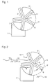
- the screening device shown in Figure 1 comprises a framework 1 which supports a generally cylindrical chamber formed by a deflector plate 7, screen panel 2 and shield plate 6.
- the deflector plate 7, screen panel 2 and shield plate 6 each, in section, extend around approximately a quarter of a circle with the fourth quarter being left open.
- the chamber is disposed with its axis generally horizontal so that the open quarter is in an upper part of the side receiving the liquid flow and the screen panel in the lower portion of the other side and opening into the channel for screened liquid.
- liquid usually water
- the open quarter then forms an unscreened inlet from a first channel and the screen panel forms a screened outlet to a second channel.
- the screen panel 2 may take any suitable form to pass only debris of a certain minimum size.
- the screen panel 2 may be replaceable and may comprise a fixed grid which supports a replaceable mesh with smaller holes.
- a cleaning drum 3 is provided. This comprises a plurality of blades 4 mounted radially.
- the cleaning drum 3 is rotatably mounted by bearing assembly 5 concentrically within the cylindrical chamber formed by deflector plate 7, screen panel 2 and shield plate 6.
- the blades 4 act as a water wheel so that the cleaning drum 3 is driven to rotate by the flow of water from the inlet to and out of screen panel 2.
- End portions of the blades 4 may be angled backwards relative to the direction of rotation in use of the device and are provided with sealing strips 8 or brushes to provide a seal to the walls of the chamber and also effect the cleaning of the screen panel 2.
- the deflector plate 7 is provided in this embodiment to ensure a good head of water to provide sufficient power to drive the cleaning drum 3.
- the screen may retain solid debris when the cleaning drum stops rotating and so the deflector plate 7 is preferably omitted in applications where a sufficient head of water to drive the cleaning drum can be expected.
- the use of the apparatus is shown in Figure 2.
- the liquid on the inlet side of the device contains large debris items 13 and small debris items 14. Both large and small debris items 13, 14 will flow into and around the screen as indicated by arrows.
- the smaller debris items 14 may pass through the screen panel 2 but larger debris items 13 are prevented from doing so. These are then picked up and swept around by rotation of the cleaning drum.
- the shield plate 6 prevents the larger debris items 13 from being ejected at the outlet side of the screen and they are instead ejected through the inlet, back into the main liquid flow.
- FIGs 3 and 4 show the screening device of the invention used in a municipal wastewater channel.
- the wastewater channel comprises a main channel 9 (first channel) and an overflow channel 12 (second channel) separated by a wall on top of which the screen device 11 is mounted.
- the water level 10 in the main channel 9 is relatively low and the screening device is not employed.
- the screen 11 becomes operative.
- the water level 10 is above the level of the inlet to the screen 11 allowing water to flow into and through the screen 11 to the overflow channel 12.
- Small debris items 14 may pass through the screening device 11 but larger items 13 are returned to the main flow preventing blockage of the overflow channel 12. It has also been found that the splashing which occurs upon rotation of the cleaning drum 3 in the screening device 11 tends to discourage floating debris from entering the screening device 11 thereby increasing its effectiveness.
- the screening device 11 is preferably arranged so as to be self-operating, driven by the flow of water through it. However, in case this flow does not provide sufficient motive power, an additional, e.g. electric, motor can be provided to drive the cleaning drum 3. Appropriate sensors e.g. float switches, may also be provided to automatically turn on the motor if the waste water level rises to the appropriate level.
- FIG. 5 A second embodiment of the present invention is shown in Figures 5 and 6. This embodiment may be used in similar applications, and in a similar way, to the first embodiment.
- the screening device 20 of the second embodiment comprises a framework 21 which supports a generally part-cylindrical screen plate 22 and, at the lower part, a drum 23 which carries a plurality of paddles blades 24. Mounted at one end of the drum 23 is a sprocket 25 over which passes a belt or chain 26, which in turn passes over an upper sprocket 27.
- the upper sprocket 27 is mounted to a bobbin 28 disposed within the generally part-cylindrical screen plate 22 and has mounted thereon a plurality of brushes 29.
- the brushes 29 sweep the inner surface of the screen plate 22 and remove debris from it.
- a deflector plate 30 is provided to direct liquid flowing through the screen in high fluid conditions onto the left side (as shown) of the drum 23.
- Figure 6 shows the screen device of the second embodiment in use.
- Water on the inlet side of the device flows into the screening chamber defined by generally part-cylindrical screen plate 22 and through the screen plate, falling onto drum 23.
- the water falling onto paddles 24 drives drum 23 to rotate which in turn drives bobbin 28 causing brushes 29 to sweep the inner surface of the screen 22.
- the water on the inlet side may include small debris items 14 and larger debris items 13 suspended or floating.
- the smaller debris items 14 pass through screen plate 22 but larger debris items 13 are trapped and swept out of screen plate 22 by brushes 29 on bobbin 28.
- the height of the fall of the water onto paddle drum 23 and the gearing effected by the relative sizes of sprockets 25 and 27 can be varied to ensure that bobbin 28 is driven at an appropriate speed, and with appropriate force, in expected flow conditions.
- a motor may be connected directly to sprocket 27 to drive bobbin 28 either supplementing or replacing the paddle drum 23.
- the screening device of the present invention may be constructed at any size, diameter and length, appropriate to the use to which it is to be put.
Landscapes
- Chemical & Material Sciences (AREA)
- Chemical Kinetics & Catalysis (AREA)
- Engineering & Computer Science (AREA)
- Emergency Management (AREA)
- Health & Medical Sciences (AREA)
- Life Sciences & Earth Sciences (AREA)
- Business, Economics & Management (AREA)
- Hydrology & Water Resources (AREA)
- Public Health (AREA)
- Water Supply & Treatment (AREA)
- Filtration Of Liquid (AREA)
- Separation Of Solids By Using Liquids Or Pneumatic Power (AREA)
- Cleaning In General (AREA)
Abstract
Description
Claims (8)
- A screening device comprising a generally cylindrical, horizontally disposed chamber (2, 6, 7) having an unscreened inlet from a first channel in a first side and a screened outlet (2) to a second channel in a lower portion of a second side; and a rotatable cleaning member (3) disposed within said chamber and arranged to rotate with a flow of water from said inlet to said screened outlet to sweep said screened outlet, and to return debris swept from said screened outlet to said first channel.
- A screening device according to claim 1 wherein said cleaning member (3) comprises a plurality of radial blades (4) extending generally parallel to the axis of said chamber and for substantially the whole length thereof.
- A screening device according to claim 2 wherein each of said radial blades (4) is provided with a flexible web (8) at its outer most end to form a seal with the wall of said chamber.
- A screening device according to claim 1 further comprising a paddle drum (23) positioned below said screened outlet (2) so as to be driven to rotate by liquid flowing out of said screened outlet and drive means (25, 26, 27) connecting said paddle drum (23) to said rotatable cleaning member (28, 29) so that rotation of said paddle drum drives said rotatable cleaning member.
- A screening device according to claim 4 wherein said rotatable cleaning member comprises a bobbin (28) having mounted thereon at least one brush (29) arranged to sweep said screened outlet.
- A screening device according to claim 4 or 5 wherein said drive means comprises first and second sprockets (25, 27) respectively provided on said paddle drum (23) and said rotatable cleaning member (28, 29) and a belt or chain (26) connecting said first and second sprockets.
- A screening device according to any one of claims 1 to 6 wherein said cleaning member (3, 28, 29) is adapted to be rotatable under the pressure of the flow of liquid from said inlet to said screen outlet without additional motive power.
- A screening device according to any one of claims 1 to 6 further comprising a motor for driving said rotating cleaning member to rotate.
Applications Claiming Priority (4)
| Application Number | Priority Date | Filing Date | Title |
|---|---|---|---|
| GB0100754 | 2001-01-11 | ||
| GB0100754A GB2370999A (en) | 2001-01-11 | 2001-01-11 | A screening device with a rotating cleaning member |
| GB0114039 | 2001-06-08 | ||
| GB0114039A GB0114039D0 (en) | 2001-06-08 | 2001-06-08 | Screening device |
Publications (2)
| Publication Number | Publication Date |
|---|---|
| EP1223252A2 true EP1223252A2 (en) | 2002-07-17 |
| EP1223252A3 EP1223252A3 (en) | 2002-12-18 |
Family
ID=26245549
Family Applications (1)
| Application Number | Title | Priority Date | Filing Date |
|---|---|---|---|
| EP01310147A Withdrawn EP1223252A3 (en) | 2001-01-11 | 2001-12-04 | Screening device |
Country Status (2)
| Country | Link |
|---|---|
| EP (1) | EP1223252A3 (en) |
| JP (1) | JP3909244B2 (en) |
Cited By (2)
| Publication number | Priority date | Publication date | Assignee | Title |
|---|---|---|---|---|
| EP2116649A2 (en) | 2008-05-05 | 2009-11-11 | Jörg-Michael Dipl.-Ing. Steinhardt | Screening device with a device to remove the items being screened |
| CN108095058A (en) * | 2018-02-07 | 2018-06-01 | 洛阳景森农业有限公司 | A kind of starch from sweet potato production slash cylinder assembly |
Families Citing this family (6)
| Publication number | Priority date | Publication date | Assignee | Title |
|---|---|---|---|---|
| JP4522750B2 (en) * | 2004-05-31 | 2010-08-11 | 株式会社日立プラントテクノロジー | Sediment separation and transfer device |
| JP4489717B2 (en) * | 2006-03-16 | 2010-06-23 | 株式会社日立プラントテクノロジー | Operation management system for screens in merging pipes. |
| JP4611238B2 (en) * | 2006-04-17 | 2011-01-12 | 株式会社日立プラントテクノロジー | Operation management system for screens in combined pipes |
| JP4846657B2 (en) * | 2007-05-25 | 2011-12-28 | 株式会社日立プラントテクノロジー | Overflow water dust remover |
| JP4738382B2 (en) * | 2007-06-01 | 2011-08-03 | 株式会社日立プラントテクノロジー | Overflow water dust remover |
| CN107499466A (en) * | 2017-09-04 | 2017-12-22 | 郑州大学 | A kind of river course water-surface cleaning device |
Family Cites Families (7)
| Publication number | Priority date | Publication date | Assignee | Title |
|---|---|---|---|---|
| GB571488A (en) * | 1943-09-21 | 1945-08-27 | Robert Charles Chinnery Dalby | Improvements in and relating to screening apparatus for the removal of insoluble solids from liquids |
| US4424129A (en) * | 1982-06-28 | 1984-01-03 | Bunger Richard E | Dewatering apparatus for waste recovery systems |
| DE4237123C2 (en) * | 1992-11-03 | 1995-02-16 | Hans Georg Huber | Device for cleaning large amounts of water from screenings |
| DE4325584C2 (en) * | 1993-07-30 | 1996-08-22 | Giehl Klaus Ulrich | Device for the retention of floating substances on a hold-up threshold of a rain relief system |
| DE19517101C1 (en) * | 1995-05-10 | 1996-12-05 | Huber Hans Gmbh Maschinen Und | Removal system for floating solids in rainwater overflow |
| DE19539882C2 (en) * | 1995-10-26 | 2000-03-23 | Huber Hans Gmbh Maschinen Und | Device for washing contaminated screenings or screenings, especially in sewage treatment plants |
| GB9601248D0 (en) * | 1996-01-23 | 1996-03-27 | Thames Water Utilities | A screen |
-
2001
- 2001-12-04 EP EP01310147A patent/EP1223252A3/en not_active Withdrawn
-
2002
- 2002-01-10 JP JP2002003504A patent/JP3909244B2/en not_active Expired - Fee Related
Cited By (5)
| Publication number | Priority date | Publication date | Assignee | Title |
|---|---|---|---|---|
| EP2116649A2 (en) | 2008-05-05 | 2009-11-11 | Jörg-Michael Dipl.-Ing. Steinhardt | Screening device with a device to remove the items being screened |
| US8021544B2 (en) | 2008-05-05 | 2011-09-20 | Steinhardt Joerg-Michael | Wastewater screening device |
| US8029666B2 (en) | 2008-05-05 | 2011-10-04 | Steinhardt Joerg-Michael | Wastewater screening device |
| US8029665B2 (en) | 2008-05-05 | 2011-10-04 | Steinhardt Joerg-Michael | Wastewater screening device |
| CN108095058A (en) * | 2018-02-07 | 2018-06-01 | 洛阳景森农业有限公司 | A kind of starch from sweet potato production slash cylinder assembly |
Also Published As
| Publication number | Publication date |
|---|---|
| JP3909244B2 (en) | 2007-04-25 |
| JP2002320802A (en) | 2002-11-05 |
| EP1223252A3 (en) | 2002-12-18 |
Similar Documents
| Publication | Publication Date | Title |
|---|---|---|
| US20050230317A1 (en) | Watershed runoff drainage device & method | |
| US4597864A (en) | Waste materials filtering apparatus | |
| CA2459443C (en) | Screening apparatus | |
| KR100823236B1 (en) | Radial Initial Water Treatment System | |
| EP1223252A2 (en) | Screening device | |
| US7267763B2 (en) | Water intake screen with circular filter panel | |
| KR101117776B1 (en) | Removal apparatus of adulteration | |
| JP4274467B2 (en) | Filtration device | |
| KR101827506B1 (en) | Floating matter Removing Apparatus of Intake Station | |
| KR100543962B1 (en) | Fine wood screen type dust treatment device | |
| GB2370999A (en) | A screening device with a rotating cleaning member | |
| KR200359286Y1 (en) | Debris discharge apparatus | |
| KR100593175B1 (en) | Mobile Float Device to Remove Float in River | |
| KR100741992B1 (en) | Disc screens for manure and contaminant treatment of wastewater and livestock wastewater | |
| SE433073B (en) | DEVICE FOR CLEANING OF LIQUID MEDIA, LIKE THE WASTE WATER | |
| GB2279889A (en) | Rotary drum filter | |
| CN220317440U (en) | Sewage purification tank with water seepage prevention structure | |
| KR102772440B1 (en) | Horizontal Drum Screen for Improved Cleaning of Coarse Material | |
| WO1996027422A1 (en) | Rotating screen and drive unit | |
| KR100616725B1 (en) | Vibrator with manual rotary device | |
| CN223416890U (en) | A rotating net bag type sewage interception system | |
| CN220695973U (en) | Anti-blocking sewage solid filtering device | |
| JP2838009B2 (en) | Fine dust remover | |
| JP3001177B2 (en) | Dust prevention device at intake using multiple rotating disk type screen | |
| CN221461359U (en) | Urban anti-blocking blow-down pipe |
Legal Events
| Date | Code | Title | Description |
|---|---|---|---|
| PUAI | Public reference made under article 153(3) epc to a published international application that has entered the european phase |
Free format text: ORIGINAL CODE: 0009012 |
|
| AK | Designated contracting states |
Kind code of ref document: A2 Designated state(s): AT BE CH CY DE DK ES FI FR GB GR IE IT LI LU MC NL PT SE TR |
|
| AX | Request for extension of the european patent |
Free format text: AL;LT;LV;MK;RO;SI |
|
| PUAL | Search report despatched |
Free format text: ORIGINAL CODE: 0009013 |
|
| AK | Designated contracting states |
Kind code of ref document: A3 Designated state(s): AT BE CH CY DE DK ES FI FR GB GR IE IT LI LU MC NL PT SE TR |
|
| AX | Request for extension of the european patent |
Free format text: AL;LT;LV;MK;RO;SI |
|
| 17P | Request for examination filed |
Effective date: 20030130 |
|
| AKX | Designation fees paid |
Designated state(s): DE ES GB GR IE |
|
| 17Q | First examination report despatched |
Effective date: 20070703 |
|
| RIC1 | Information provided on ipc code assigned before grant |
Ipc: E03F 5/12 20060101AFI20150212BHEP Ipc: B01D 29/01 20060101ALI20150212BHEP |
|
| GRAP | Despatch of communication of intention to grant a patent |
Free format text: ORIGINAL CODE: EPIDOSNIGR1 |
|
| INTG | Intention to grant announced |
Effective date: 20150319 |
|
| STAA | Information on the status of an ep patent application or granted ep patent |
Free format text: STATUS: THE APPLICATION IS DEEMED TO BE WITHDRAWN |
|
| 18D | Application deemed to be withdrawn |
Effective date: 20150730 |