EP1223373A2 - Soupape commandée par moteur électrique - Google Patents
Soupape commandée par moteur électrique Download PDFInfo
- Publication number
- EP1223373A2 EP1223373A2 EP02000576A EP02000576A EP1223373A2 EP 1223373 A2 EP1223373 A2 EP 1223373A2 EP 02000576 A EP02000576 A EP 02000576A EP 02000576 A EP02000576 A EP 02000576A EP 1223373 A2 EP1223373 A2 EP 1223373A2
- Authority
- EP
- European Patent Office
- Prior art keywords
- actuator
- valve
- yoke
- spring
- shaft
- Prior art date
- Legal status (The legal status is an assumption and is not a legal conclusion. Google has not performed a legal analysis and makes no representation as to the accuracy of the status listed.)
- Granted
Links
Images


Classifications
-
- F—MECHANICAL ENGINEERING; LIGHTING; HEATING; WEAPONS; BLASTING
- F16—ENGINEERING ELEMENTS AND UNITS; GENERAL MEASURES FOR PRODUCING AND MAINTAINING EFFECTIVE FUNCTIONING OF MACHINES OR INSTALLATIONS; THERMAL INSULATION IN GENERAL
- F16K—VALVES; TAPS; COCKS; ACTUATING-FLOATS; DEVICES FOR VENTING OR AERATING
- F16K31/00—Actuating devices; Operating means; Releasing devices
- F16K31/02—Actuating devices; Operating means; Releasing devices electric; magnetic
- F16K31/04—Actuating devices; Operating means; Releasing devices electric; magnetic using a motor
- F16K31/047—Actuating devices; Operating means; Releasing devices electric; magnetic using a motor characterised by mechanical means between the motor and the valve, e.g. lost motion means reducing backlash, clutches, brakes or return means
-
- F—MECHANICAL ENGINEERING; LIGHTING; HEATING; WEAPONS; BLASTING
- F16—ENGINEERING ELEMENTS AND UNITS; GENERAL MEASURES FOR PRODUCING AND MAINTAINING EFFECTIVE FUNCTIONING OF MACHINES OR INSTALLATIONS; THERMAL INSULATION IN GENERAL
- F16K—VALVES; TAPS; COCKS; ACTUATING-FLOATS; DEVICES FOR VENTING OR AERATING
- F16K27/00—Construction of housing; Use of materials therefor
- F16K27/02—Construction of housing; Use of materials therefor of lift valves
- F16K27/0209—Check valves or pivoted valves
- F16K27/0218—Butterfly valves
-
- F—MECHANICAL ENGINEERING; LIGHTING; HEATING; WEAPONS; BLASTING
- F16—ENGINEERING ELEMENTS AND UNITS; GENERAL MEASURES FOR PRODUCING AND MAINTAINING EFFECTIVE FUNCTIONING OF MACHINES OR INSTALLATIONS; THERMAL INSULATION IN GENERAL
- F16K—VALVES; TAPS; COCKS; ACTUATING-FLOATS; DEVICES FOR VENTING OR AERATING
- F16K31/00—Actuating devices; Operating means; Releasing devices
- F16K31/44—Mechanical actuating means
- F16K31/53—Mechanical actuating means with toothed gearing
- F16K31/535—Mechanical actuating means with toothed gearing for rotating valves
Definitions
- the present invention relates to an operating device having an output shaft for rotating an object to be operated, and a valve system having such an operating device and a valve serving as the object to be operated.
- the present invention relates to a spring return type operating device having a return spring for rotating an object to be operated in a return direction, and a spring return type valve system having this kind of operating device and a valve.
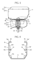
- a conventional spring return type valve system includes a valve 70 inserted in a fluid channel (not shown), a return spring unit 80 mounted on the valve 70, and an electric actuator 90 mounted on the return spring unit 80.
- the return spring unit 80 has a housing 81, a rotating shaft 82, and a return spring 87 interposed therebetween.
- the return spring unit 80 is configured so that the spring force from the return spring 87 rotates the rotating shaft 82 and a valve shaft 72 of the valve 70 coupled thereto in one direction, e.g., in the direction that closes the valve.
- the electric actuator 90 rotates its output shaft 92 with a motor 96 via a reduction mechanism 97 consisting of a gear train so that the valve shaft 72 coupled to the actuator output shaft 92 is rotated against the spring force of the return spring 87 through the medium of the rotating shaft 82 of the return spring unit 80.
- valve shaft 72 and a valve element 75 integral therewith are rotated by the electric actuator 90 to a predetermined rotational position so as to adjust the opening of the valve 70, whereby the flow rate of the fluid flowing through the fluid channel is controlled.
- the valve shaft 72 is rotated in the closing direction by the spring force of the return spring 87 to close the valve 70.
- the housing 81 of the return spring unit 80 includes an outer housing and an inner housing.
- the outer housing has a lower flange 84 thereof fixed to a flange 74 of the housing 71 of the valve 70 with bolts 100.
- the inner housing is fitted to a socket part 73 of the housing 71 and supports the rotating shaft 82 of the return spring unit 80.
- a recess 83 formed in the inner housing accommodates a joint 110 for coupling the rotating shaft 82 to the valve shaft 72.
- the housing 91 of the electric actuator 90 includes an upper housing and a lower housing. The upper housing accommodates the reduction mechanism 97.
- the lower housing fits a socket part 85 of an upper flange 86 of the return spring unit 80, and has a flange 95 which is fixed to the upper flange 86 with bolts 101.
- the lower housing has a recess 93 which accommodates a joint 111 for coupling the actuator output shaft 92 to the rotating shaft 82 of the return spring unit 80.
- the top end portion of the valve shaft 72, the joint 110, and the bottom end portion of the rotating shaft 82 are accommodated in the recess 83 of the housing 81.
- the top end portion of the rotating shaft 82, the joint 111, and the bottom end portion of the output shaft 92 are accommodated in the recess 93 of the housing 91.
- valve shaft 72 Take, for example, the case of coupling the valve shaft 72 to the joint 110.
- a flat-faced part 72a formed on the valve shaft 72 must be aligned to a flat part of a fit hole formed in the joint 110.
- the reference numerals 82a, 82b, and 92a show the flat-faced parts.
- the accommodation of the joints 110 and 111 in the recesses 83 and 93 of the housings 81 and 91 makes the directions of the flat-faced parts invisible from exterior, deteriorating the workability in coupling the corresponding ones of the valve shaft 72, the rotating shaft 82, and the output shaft 92 with the joints 110 and 111.
- the electric actuator 90 In cases where the electric actuator 90 suffers a breakdown that the output shaft 92 becomes unrotatable due to such reasons as a gear breakage in the reduction mechanism 97, the electric actuator 90 is detached from the valve system for repair. On this occasion, if under a work environment where the rotational position of the valve shaft 72 cannot be observed visually from exterior, the operator can possibly remove the bolt 101 despite incomplete closure of the valve 70. In this case, the entire electric actuator 90 might rotate abruptly due to the spring force from the return spring 87. With valves of larger sizes in particular, the return spring 87 has a great spring force and it is sometimes impossible for the operator to quickly hold the electric actuator 90 from rotating with strong force. Moreover, when the electric actuator 90 is detached with the valve 70 open, the load on the return spring 87 decreases rapidly. The result is that the spring force from the return spring 87 rotates the valve shaft 72 sharply in the closing direction. Such sharp closure of the valve 70 can cause a water hammer, possibly breaking the valve 70.
- the electric actuator 90 is detached before the lower flange 84 of the return spring unit 80 is attached to or detached from the flange 71 of the valve 70 by using a screwdriver or other tools.
- the valve system is configured such that the upper flange 86 of the return spring unit 80 has a diameter considerably greater than that of the lower flange 84, or that the two flanges have a considerably small gap therebetween, the tools to loosen and tighten the bolt 100 interferes with the upper flange 86, finding the operation difficult.
- Using an L-tipped tool to operate laterally from the housing 81 deteriorates workability.
- the housing 81 of the return spring unit 80 and the housing 71 of the valve 70 are in direct contact with each other.
- the object to be controlled by the valve system is hot fluid such as steam
- the valve 70 becomes high in temperature. Therefore, the housing 81 also becomes high in temperature because of the heat conducting from the valve 70, which makes it difficult to detach the return spring unit 80.
- the heat conducting from the valve 70 thermally degrades the return spring unit 80 and the actuator 90.
- the return spring unit 80 and the actuator 90 decrease in temperature with internal condensation, becoming prone to rust and short-circuit breakage.
- Another object of the present invention is to provide a valve system comprising an operating device of this type and a valve serving as the object to be operated, the valve system being capable of quick, safe assembling and disassembling operations.
- a spring return type operating device comprises: a yoke adapted to be mounted on an object to be operated having a rotating shaft; an actuator having a drive unit and an output shaft rotated by the drive unit, the actuator being detachably mounted on the yoke; and a spring unit detachably mounted on the yoke so as to lie between the actuator and the object to be operated.
- the spring unit has a rotating shaft and a return spring for producing a spring force for rotating the rotating shaft in one direction.
- the rotating shaft has a first end portion adapted to be coupled to the rotating shaft of the object to be operated and a second end portion coupled to the output shaft of the actuator.
- the yoke defines a space for accommodating at least part of the actuator and at least part of the spring unit.
- the space has an open face for making the coupling portions of the first and second end portions of the rotating shaft of the spring unit with the rotating shaft of the object to be operated and the output shaft of the actuator, respectively, visible from exterior.
- the spring return type operating device of the present invention at the occasion of mounting the spring unit and the actuator onto the yoke that is mounted on the object to be operated, it is possible to couple the first and second end portions of the rotating shaft of the spring unit to the rotating shaft of the object to be operated and the output shaft of the actuator while seeing their respective coupling portions from exterior through the open face of the space which the yoke defines.
- the effect that the heat from the object to be operated has on the spring unit and the actuator is reduced by the yoke which lies between the object to the operated and the spring unit/the actuator.
- the heat from the object to be operated is radiated to the ambient air through the yoke before conducting to the spring unit and the actuator.
- the yoke exercises the function of absorbing heat from the ambient air to relieve the cooling action due to the heat from the object to be operated. In this way, the effect of the heat conducting from the object to be operated is relieved.
- the spring unit and the actuator improve in durability, and condensation is prevented.
- the drive unit of the actuator is preferably composed of an electric motor.
- the rotational position of the output shaft of the actuator and hence the rotational position of the rotating shaft of the object to be operated can be adjusted easily and precisely by the electric motor.
- the yoke preferably has a bottom wall and side walls that are extended from both ends of the bottom wall and are opposed to each other.
- the bottom wall of the yoke is provided with a first fitting part to which the object to be operated is attached.
- Second fitting parts for the spring unit to be mounted on are arranged at intermediate portions of the side walls.
- Third fitting parts for the actuator to be mounted on are arranged on distal end portions of the side walls.
- the yoke is formed in a general U shape as viewed from the front.
- This yoke is extremely simple in configuration and capable of fabrication at low cost.
- the side walls of the yoke define therebetween a wide open face such as facilitates the coupling operations described above.
- the second fitting parts are preferably arranged in such positions that the spring unit mounted on these second fitting parts and the first fitting part come close to each other at their opposed surfaces.
- the third fitting parts are preferably arranged in such positions that the actuator mounted on these third fitting parts and the spring unit mounted on the second fitting parts come close to each other at their opposed surfaces.
- the yoke cannot be mounted on the object to be operated at its first fitting part as long as the spring unit is on the second fitting parts of the yoke.
- the spring unit cannot be mounted on the second fitting parts as long as the actuator is on the third fitting parts.
- the yoke is mounted on the object to be operated before the spring unit and the actuator are mounted on the yoke in this order.
- the actuator and the spring unit are detached from the yoke in this order before the yoke is detached from the object to be operated. In this way, the order of attachment and the order of detachment determine by themselves for safety operations. In addition, all the attaching and detaching operations can be performed from above with excellent workability.
- the spring unit and the actuator detached from the yoke the rotational position of the rotating shaft of the object to be operated can be visually observed from exterior for proper operations.
- the first fitting part of the yoke preferably has a shaft hole and a plurality of bolt through holes.
- the shaft hole is formed through the bottom wall of the yoke, and the rotating shaft of the object to be operated is inserted therethrough.
- the bolt through holes are formed in the bottom wall concentrically about the shaft hole at regular intervals in angle.
- the object to be operated is provided with a plurality of bolt holes consistent with the plurality of bolt through holes.
- the yoke is bolted to the object to be operated with the rotating shaft of the object to be operated inserted through the shaft hole in the first fitting part of the yoke.
- the flexibility in the mounting orientation of the yoke with respect to the object to be operated determines according to the angular intervals of the bolt through holes. Therefore, the spring return type operating device can be mounted on the object to be operated in desired orientation.
- the bolt through holes may be circular in section. Bolt through holes of arced sections, however, allow further adjustments in the mounting location of the yoke, increasing the forming tolerances of the bolt through holes and the bolt holes.
- the bolt through holes be long holes extending in radial directions of the shaft hole.
- the yoke of the operating device can be mounted on various types of objects to be operated having bolt holes at different radial positions. This enhances the operating device in versatility.
- the second and third fitting parts are preferably formed by cutting and erecting inward the corresponding portions of the side walls of the yoke.
- the fitting parts can be provided at low cost.
- the second and third fitting parts are preferably arranged apart from each other as seen from above.
- the second and the third fitting parts of the yoke can be accessed from above with improved workability.
- the rotating shaft of the object to be operated or the output shaft of the actuator is preferably provided with indicating means for allowing the visual observation of a predetermined rotational position thereof (for example, a full close position or full open position), such as a pointer or a marking.
- the rotating shaft of the object to be operated and the actuator output shaft can be easily observed visually for rotational position. This ensures safety operations.
- a spring return type valve system comprises: a valve having a valve shaft arranged rotatably and a valve element integral with the valve shaft; a yoke mounted on the valve; an actuator having a drive unit and an output shaft rotated by the drive unit, the actuator being detachably mounted on the yoke; and a spring unit having a rotating shaft and a spring for producing a spring force for rotating the rotating shaft in one direction, the spring unit being detachably mounted on the yoke so as to lie between the actuator and the valve, the rotating shaft being coupled at both end portions to the output shaft and the valve shaft, respectively.
- the yoke defines a space for accommodating at least part of the actuator and at least part of the spring unit. The space has an open face for making the coupling portions of the end portions of the rotating shaft of the spring unit with the valve shaft and the output shaft of the actuator visible from exterior.
- the spring return type valve system of the present invention it is possible to couple the end portions of the rotating shaft of the spring unit to the valve shaft and the actuator output shaft easily while visually observing their respective coupling portions.
- the effect of heat conducting from the valve is reduced by the yoke.
- the spring return type valve system of the present invention may be configured in various forms for various effects.
- a spring return type valve system 1 comprises a valve 2, a spring unit 3, an actuator 4, and a yoke 5.
- the valve 2 is inserted in the middle of a fluid channel, not shown, to control the flow rate of fluid that flows the fluid channel.
- the spring unit 3 subjects the valve 2 to a spring force for rotating the valve 2 in one direction, e.g., a closing direction.
- the actuator 4 can rotate the valve 4 both in the opening and closing directions.
- the yoke 5 is detachably attached to the valve 2.
- the spring unit 3 and the actuator 4 are attached to the yoke 5 in this order.
- the valve 2 has a housing 21 and a valve shaft 22 which is rotatably supported by the housing 21.
- a rotary valve element (not shown) fixed to the valve shaft 22 is accommodated in the housing 21 along with the valve shaft 22.
- the rotary valve element is one corresponding to the valve element 75 shown in Fig. 11, and is selected from among valve elements of ball type, butterfly type, eccentric type, and the like depending on the intended use.
- the valve shaft 22 is coupled to the actuator 4 via the spring unit 3. The rotational operation of the valve shaft 22 by the actuator 4 rotates the valve element to change the valve opening, thereby controlling the flow rate of the fluid.
- a top surface 21a of the housing 21 of the valve 2 constitutes a mounting surface for the yoke 5 to be attached to.
- This housing top surface 21a has a shaft hole which the valve shaft 2 is passed through.
- a plurality of, e.g., four bolt holes (not shown) to be used for attaching the yoke 5 to the valve 2 are formed concentrically about the shaft hole at regular intervals in angle.
- the extremity or distal end portion of the valve shaft 22 is protruded from the housing top surface 21a. This extremity is chamfered on the periphery so as to make a flat-faced part 22a of square section to be used for coupling with the spring unit 3.
- the spring return type valve system 1 has first valve opening indicating means for indicating a predetermined valve opening position, e.g., the closed position.
- the first valve opening indicating means is composed of a marking 22b and a mark 21b.
- the marking 22b is arranged on the periphery of the extremity of the valve shaft 22.
- the mark 21b is a projection or the like for indicating the closed position, arranged on the top periphery of the housing 21.
- the marking 22b indicates the current rotational position of the valve element which makes integral rotation with the valve shaft 22. This marking 22b coincides with the mark 21b when the valve element is in the closed position.
- Such valve opening indication is especially convenient for ball type valve elements which allow valve shaft rotations of 360° or more.
- the mark 21b may be arranged for a plurality of predetermined valve opening positions.
- the spring unit 3 has a housing 31 and a rotating shaft 32 rotatably supported by the housing 31.
- the housing 31 has a body 31a and a lid 31b fixed on the top.
- the rotating shaft 32 is protruded at both end portions from the top and bottom of the housing body 31a, respectively.
- the rotating shaft 32 has a square hole 32a formed through its shaft center. This square hole 32a is fitted to the flat-faced part 22a of the valve shaft 22 and a flat-faced part 42a of an output shaft 42 of the actuator 4.
- the housing body 31a contains a return spring 33 of, for example, spiral type.
- This return spring 33 corresponds to the return spring 87 shown in Fig. 11.
- Fig. 5 outlines the return spring 33 in dashed lines.
- the return spring 33 is fixed at both end portions to an inner surface of the housing body 31a and the rotating shaft 32, respectively, so as to produce a return force for rotating the rotating shaft 32 in one direction, e.g., the closing direction.
- a stopper (not shown) for determining the rotational limit position of the rotating shaft 32 in the closing direction is arranged on the inner surface of the housing body 31a.
- the valve element of the valve 2 closes completely when in this rotational limit position.
- the spiral type return spring 33 is configured to produce a torque T1 in the closing direction that is sufficient to maintain the valve element to the closed position when the rotating shaft 32 is in contact with the stopper at the rotational limit position (valve opening 0%).
- the return spring 33 is also configured so that the produced torque increases as the valve shaft 22 is rotated in the opening direction by the actuator 4.
- T2 represents the torque produced at a valve opening of 100%.
- the lid 31b of the housing 31 of the spring unit 3 is fixed to the housing body 31a with bolts 34. These bolts 34 are accessible only from below the housing body 31a. That is, the bolts 34 can be removed to detach the lid 31b from the housing body 31a only if the spring unit 3 is detached from the yoke 5. Such configuration prevents the lid 31b from being accidentally removed from the housing body 31a despite the intention of detaching the spring unit 3 from the yoke 5.
- the housing 31 is attached to the yoke 5 with bolts 62 at its fitting parts 31c arranged on both sides. More specifically, the housing body 31a and the lid 31b have bolt through holes formed therethrough in these fitting parts 31c. The bolts 62 are inserted through the bolt through holes from above the lid 31b.
- the electric actuator 4 used in the present embodiment is one according to the proposal of the present inventors, described in Japanese Patent Laid-Open Publication No.Hei 10-164878. Acceptable alternatives thereto include electric actuators of different types and fluid actuators.
- the electric actuator 4 has a housing 41 which includes a body 41a and a lid 41b fixed to the body 41a with bolts 44.
- This housing 41 rotatably supports the actuator output shaft 42.
- the housing body 41a contains a motor, a reduction mechanism, an electromagnetic clutch, a rheostatic brake mechanism, a control circuit, and so on (none are shown).
- the motor and the electromagnetic clutch operate under the control of the control circuit.
- the rotational power from the motor is transmitted through the reduction mechanism to the output shaft 42 so that the output shaft 42 rotates.
- the electromagnetic clutch is interposed between the motor and the reduction mechanism to allow/interrupt the transmission of the rotational power from the motor to the reduction mechanism.
- the electric actuator 4 is fixed to the yoke 5 with bolts 63 at fitting parts 41c arranged on both side portions of its housing body 41a. The bolts are tightened from above.
- the extremity of the output shaft 42 of the electric actuator 4 is protruded from the bottom of the housing body 41a. The extremity is chamfered on the periphery so as to make the flat-faced part 42a which is square in section.
- the flat-faced part 42a fits into the square hole 32a in the rotating shaft 32 of the spring unit 3, whereby the actuator output shaft 42 is coupled to the rotating shaft 32 of the spring unit 3.
- the spring return type valve system 1 has second valve opening indicating means. As shown in Figs. 1 and 2, the second valve opening indicating means is composed of a pointer 45 and a mark 41d.
- the pointer 45 is arranged on the proximal end portion of the flat-faced part 42a of the actuator output shaft 42.
- the mark 41d is a projection or the like for indicating the closed position, arranged on a lower end portion of the periphery of the housing body 41a of the actuator 4.
- the pointer 45 indicates the current rotational position of the valve element which makes integral rotation with the actuator output shaft 42.
- the extremity 45a of the pointer 45 coincides with the mark 41d when the valve element is in the closed position.
- the mark 41d is preferably arranged as shown in Fig. 1, or at a central portion of an open periphery that extends between both side walls 52 and 52' of the yoke 5.
- the mark 41d may be arranged on every valve opening position desired.
- the marking 22b arranged on the valve shaft 22 may be replaced with a pointer similar to the pointer 45.
- the pointer 45 may be replaced with a marking similar to the marking 22b.
- the yoke 5 has a bottom wall 51 and the right and left side walls 52 and 52' which are extended upward from both ends of the bottom wall 51 and are opposed to each other.
- the entire yoke 5 is formed in a general U shape as viewed from the front.
- the yoke 5 defines an accommodation space for accommodating the entire spring unit 3 and the lower half of the actuator 4.
- This accommodation space has an open top as well as open front and rear sides (in a broad sense, open faces).
- the U-shaped yoke 5 may be replaced with a yoke that has a peripheral wall provided with one or more openings corresponding to the open faces.
- the bottom wall of the yoke 5 constitutes a first fitting part 51 for the valve 2 to be attached to.
- second fitting parts 53 for the spring unit 3 to be mounted on are arranged at intermediate portions of the side walls 52 and 52' of the yoke 5.
- Third fitting parts 54 for the actuator 4 to be mounted on are arranged on the extremities or distal end portions of the side walls 52 and 52'.
- the bottom wall of the yoke 5 which makes the first fitting part 51 has a shaft hole 51a for the valve shaft 22 to be passed through loosely and four bolt through holes 51b.
- the bolt through holes 51b are arranged concentrically about the shaft hole 51a at regular intervals in angle, and are alignment with the four bolt holes formed in the top surface 21a of the housing 21 of the valve 2.
- These bolt through holes 51b are long holes extending from the shaft hole 51a in radial directions.
- the yoke 5 of such configuration can be mounted on a variety of valves 2 having bolt holes in different positions, and thus is excellent in versatility. Incidentally, it is not absolutely necessary that the bolt through holes 51b communicate with the shaft hole 51a at their proximal ends.
- the valve 2 is provided with the four bolt holes at regular intervals in angle, and the yoke 5 is provided with the four bolt through holes 51b consistent with the bolt holes. Therefore, the yoke 5 can be mounted on the valve 2 as oriented to any one of four directions having 90° differences in circumferential angle about the valve shaft 22. This increases the flexibility in the orientation of the yoke 5 with respect to the fluid channel. In other words, the spring unit 3 and the actuator 4 have greater flexibility in the orientation with respect to the fluid channel.
- the flat-faced part 22a of the valve shaft 22, the shaft hole 32a in the rotating shaft 32 of the spring unit 3, and the flat-faced part 42a of the actuator output shaft 42 each have a square section. Therefore, both the flat-faced parts 22a and 42a can be fitted to the shaft hole 32a as oriented to any one of four directions having 90° differences in circumferential angle about the axis. This increases the flexibility in establishing the coupling between the valve shaft 22 and the rotating shaft 32, and between the rotating shaft 32 and the actuator output shaft 42.
- the two second fitting parts 53 of the yoke 5 consist of two pairs of support pieces 53a, 53b, 53a', and 53b', which are the corresponding portions of the side walls 52 and 52' of the yoke 5 cut and erected inward into an L shape, respectively.
- Each of the support pieces has a screw hole 53c.
- the spring unit 3 is screwed to the second fitting parts 53 of the yoke 5 at its fitting parts 31c formed on both sides.
- the third fitting parts 54 of the yoke 5 consist of two pairs of support pieces 54a, 54b, 54a', and 54b' which are the corresponding portions of the side walls 52 and 52' of the yoke 5 cut and erected inward into an L shape, respectively.
- Each of the support pieces has a screw hole 54c. Then, the actuator 4 is screwed to the third fitting parts 54 of the yoke 5 at its fitting parts 41c formed on both sides.
- the fitting parts 31c of the spring unit 3 and the fitting parts 41c of the actuator 4, as seen from above, are arranged apart from each other by no less than the sizes of the heads of the bolts 62 and 63.
- the second fitting parts 53 and the third fitting parts 54 of the yoke 5 are arranged apart from each other as shown in Fig. 7.
- the bolts 62 can be attached to and detached from the screw holes in the support pieces 53a, 53b, 53a', and 53b', which constitute the second fitting parts 53, from above without a screwdriver or other tools interfering with the support pieces 54a, 54b, 54a', and 54b' of the third fitting parts 54 which lie above the second fitting parts 53.
- a pair of support pieces 53b and 53b' are arranged directly below the actuator 4 that is attached to the third fitting parts 54.
- the fit between the flat-faced part 42a of the actuator output shaft 42 and the shaft hole 32a in the rotating shaft 32 of the spring unit 3 and the fit between the flat-faced part 22a of the valve shaft 22 and the shaft hole 32a in the rotating shaft 32 cannot be released before the actuator 4 is detached from the yoke 5. That is, the spring unit 3 can be detached from the yoke 5 only after the actuator 4 is detached from the yoke 5.
- yoke 5 being a shaped metal plate, has a radiating function and a heat absorbing function.
- the marking 22b on the valve shaft 22 of the valve 2 is set to the mark 21b on the housing 21 of the valve 2 which indicates the closed position, whereby the valve 2 is put in a closed state.
- the yoke 5 is placed on the top surface 21a of the housing 21 of the valve 2 so that the valve shaft 22 is passed with play through the shaft hole 51a (Fig. 7) which is formed in the first fitting part 51 of the yoke 5.
- the yoke 5 is fixed to the valve 2 with the bolts 61.
- the spring unit 3 is accommodated to between the side walls 52 and 52' of the yoke 5.
- the square hole 32a in the rotating shaft 32 of the spring unit 3 is fitted to the flat-faced part 22a of the valve shaft 22 to couple the rotating shaft 32 and the valve shaft 22 (Fig. 5).
- the coupling portions of the valve shaft 22 and the rotating shaft 23 can be visually observed from exterior through the open periphery (opening) between the yoke side walls 52 and 52'.
- This allows an easy, quick coupling operation.
- the rotating shaft 32 can be coupled to the valve shaft 22 as oriented to any one of four directions having 90° differences in circumferential angles.
- the great flexibility in the orientation of the rotating shaft 32 upon coupling facilitates the assembly operation.
- the extremity 45a of the pointer 45 attached to the actuator output shaft 42 is set to the mark 41d on the actuator 4 which indicates the closed position, before the actuator 4 is accommodated to between the yoke side walls 52 and 52'.
- the flat-faced part 42a of the actuator output shaft 42 is fitted into the square hole 32a in the rotating shaft 32 of the spring unit 3, so that the actuator output shaft 42 is coupled to the rotating shaft 32 (Fig. 5). Since the coupling portions of the rotating shaft 32 and the actuator output shaft 42 are visible from exterior, the coupling operation can be performed easily and quickly.
- the flat-faced part 42a of the actuator output shaft 42 and the square hole 32a in the rotating shaft 32 have a square section. Therefore, the great flexibility in the orientation of the actuator output shaft 42 upon coupling facilitates the assembly operation.
- the spring unit 3 and the actuator 4 are thus mounted on the valve 2 via the yoke 5 in succession, completing the assembly of the spring return type valve system 1.
- the spring unit 3 and the actuator 4 can only be attached to the yoke 5 in this order. Besides, the detachment from the yoke 5 is possible only in the order of the actuator 4 and the spring unit 3.
- the four bolts 61 for fixing the first fitting part 51 of the yoke 5 to the valve 2 lies directly below the spring unit 3.
- the spring unit 3 is attached to the second fitting parts 53 of the yoke 5
- tools are hardly usable because of interference with the surroundings, failing or finding it extremely hard to remove the bolts 61.
- the two screwed to the support pieces 53b and 53b' lie directly below the actuator 4.
- the actuator 4 is attached to the third fitting parts 54, tools are hardly usable and these two bolts cannot be removed.
- the spring return type valve system 1 is configured so that the spring unit 3 and the actuator 4 can be attached to and detached from the yoke 5 in proper order alone.
- the valve 2 When the external power supply to the electric actuator 4 is interrupted, the valve 2 is closed by the spring force from the return spring 33 of the spring unit 3 (corresponding to the torque T1 shown in Fig. 9), stopping the flow of the fluid in the fluid channel.
- the actuator 4 When the actuator 4 is supplied with power, the motor output shaft and the reduction mechanism are coupled to each other drivingly through the electromagnetic clutch, and the control circuit enters an operating state.
- the control circuit makes the motor rotate in the opening direction or the closing direction so that the current valve opening coincides with a target valve opening which is set from exterior.
- the rotational power from the motor is transmitted through the electromagnetic clutch and the reduction mechanism to the output shaft 42 of the actuator 4 so that the output shaft 42 rotates.
- valve shaft 22 is rotated to the target valve opening against the spring force from the return spring 33 of the spring unit 3.
- the energization of the motor is suspended.
- the holding power of the motor maintains the valve shaft 22 to this valve opening against the spring force of the return spring 33, so that the fluid flows through the fluid channel at a flow rate corresponding to the valve opening.
- Adjustably setting the target valve opening allows variable control of the flow of the fluid.
- the valve 2 becomes high in temperature and the heat conducts from the valve 2 toward the spring unit 3 and the actuator 4.
- the heat from the valve 2 is radiated through the yoke 5. This suppresses heat conduction to the spring unit 3 and the actuator 4, reducing the thermal degradation of the spring unit 3 and the actuator 4 for improved durability.
- the entire valve 2 becomes low in temperature.
- the yoke 5 absorbs heat from the ambient air to relieve the temperature drop of the spring unit 3 and the actuator 4. This prevents or reduces condensation inside the spring unit 3 and the actuator 4, thereby avoiding rust production on metal parts and a condensation-based short of electric circuits.
- the spring return type valve system 1 comprises the first valve opening indicating means, composed of the marking 22b arranged on the valve shaft and the mark 21b arranged on the valve housing 21, and the second valve opening indicating means, composed of the pointer 45 arranged on the actuator output shaft 42 and the mark 41d arranged on the actuator housing body 41a.
- the operator can visibly observe the opening of the valve 2 from exterior, based on the position of the marking 22b with respect to the mark 21b and the position of the pointer 45 with respect to the mark 41d.
- valve 2 If the valve 2 is visually observed and found closed, the operator determines that the actuator 4 can be detached from the yoke 5 without problems. If the valve 2 is visually observed and found open, the operator determines that the detachment of the actuator 4 from the yoke 5 may cause a trouble. Then, the actuator asks an expert for detachment, repair, or replacement of the actuator 4 if necessary. Since the actuator 4 is thus detached from the yoke 5 after the visual observation of the opening of the valve 2, there no longer occur the problems associated with the actuator detachment. At the occasion of detaching the actuator 4, the bolts 63 are removed from the fitting parts 41c of the actuator housing 41 and then the actuator 4 is pulled up. Thereby, the coupling between the actuator output shaft 42 and the rotating shaft 32 of the spring unit 3 is easily released to detach the actuator 4 from the yoke 5.
- the bolts 62 are removed from the fitting parts 31c of the housing 31 of the spring unit 3 after the detachment of the actuator 4 from the yoke 5. Then, the spring unit 3 is pulled up. Thereby, the coupling between the rotating shaft 32 of the spring unit 3 and the valve shaft 22 is released to detach the spring unit 3 from the yoke 5. Even where the fluid flowing through the fluid channel is hot, the temperatures of the housing 41 of the actuator 4, the bolts 62, and the like are lowered by the radiating function of the yoke 5 for better workability.
- the spring unit 3 is configured so that the lid 31b can be removed from the housing body 31a only if the spring unit 3 is detached from the yoke 5. This eliminates the possibility that the lid 31b is accidentally removed from the housing body 31a before the detachment of the spring unit 3 from the yoke 5, thereby avoiding the problems associated with the accidental removal of the lid 31b.
- the actuator 4 and the spring unit 3 are detached from the yoke 5 before the bolts 61 are removed from the bolt holes in the housing top surface 21a of the valve 2 and the yoke 5 is lift off the valve 2.
- the assembling and disassembling operations of the spring return type valve system 1 can only be performed under the predetermined procedure. Thus, it is possible to avoid accidents due to such reasons as operator negligence.
- the forgoing first embodiment has dealt with the valve system in which the valve closes completely when the power supply to the actuator 4 is shut off.
- the valve 2 may take any opening on the interruption of the power supply.
- the valve 2 may be configured to be fully open or partly open on the interruption of the power supply.
- the foregoing first embodiment has used a flow control valve which can adjustably control the valve opening from full close through full open, whereas an on-off valve may be used instead.
- the foregoing first embodiment has dealt with the spring return type valve system which comprises the spring return type operating device composed of the spring unit 3, the actuator 4, and the yoke 5, and the flow control valve 2 as the object to be operated.
- the object to be operated is not limited to the flow control valve.
- the spring return type operating device described in the foregoing first embodiment may be used to operate such objects as dumpers, doors, folding doors of buses and phone booths, and robot arms.
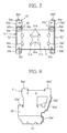
- valve system of the present embodiment corresponds to the spring return type valve system of the first embodiment without the spring unit 3. That is, the valve system is one in which the electric actuator 4 is attached to the valve 2 through the medium of a yoke 7.
- the valve shaft 22 and the actuator output shaft 42 are coupled to each other via a joint 8.
- the yoke 7 corresponds to the yoke 5 shown in Fig. 1 without the fitting parts 31c for mounting a spring unit.
- the yoke 7 is configured as the yoke 5 is. More specifically, the yoke 7 includes a bottom wall 7a as well as right and left side walls 7b which are extended upward from both sides thereof.
- the central portion of the bottom wall 7a constitutes an fitting part for attaching the yoke 7 to the top surface 21a of the housing 21 of the valve 2. That is, a shaft hole (not shown) for the valve shaft 22 to be passed through loosely is formed in the central portion of the bottom wall 7a.
- a plurality of bolt through holes are formed concentrically about the shaft hole at regular intervals in angle.
- the yoke 7 is placed on the housing top surface 21a of the valve with the valve shaft 22 passed through its shaft hole, and is fixed to the housing top surface 21a with the bolts 61.
- a pair of support pieces 7c are arranged as fitting parts on the top end portions of the side walls 7b of the yoke 7. Then, the actuator 4 is accommodated to between the side walls 7a. The fitting parts 41c of the actuator 4 are fixed to the support pieces 7c of the yoke 7 with the bolts 63.
- the joint 8 has a square hole (not shown) formed along its axis.
- the top end, or flat-faced part (not shown), of the valve shaft 22 is fitted into this square hole from below.
- the bottom end portion, or flat-faced part, of the actuator output shaft 42 is fitted into the square hole from above. That is, the valve shaft 22 and the actuator output shaft 42 are coupled to each other by the joint 8.
- the actuator 4 can be used for both the spring return type valve system of the first embodiment and the non-spring return type valve system valve system of the present embodiment.
- this non-spring return type valve system is identical to that of the spring return type valve system of the first embodiment except the absence of the spring return function from the spring unit. Therefore, description will be omitted of the operation.
- the foregoing second embodiment has dealt with the non-spring return type valve system which includes the operating device composed of the actuator 4 and the yoke 7, and the flow control valve 2 as the object to be operated.
- the object to be operated is not limited to the flow control valve. That is, the non-spring return type operating device described in the foregoing second embodiment can be used to operate such objects as dumpers.
- the flow control valve may be replaced with an on-off valve.
Landscapes
- Engineering & Computer Science (AREA)
- General Engineering & Computer Science (AREA)
- Mechanical Engineering (AREA)
- Electrically Driven Valve-Operating Means (AREA)
- Mechanically-Actuated Valves (AREA)
- Valve Housings (AREA)
Applications Claiming Priority (2)
| Application Number | Priority Date | Filing Date | Title |
|---|---|---|---|
| JP2001002875A JP3818363B2 (ja) | 2001-01-10 | 2001-01-10 | スプリングリターン型操作器 |
| JP2001002875 | 2001-01-10 |
Publications (3)
| Publication Number | Publication Date |
|---|---|
| EP1223373A2 true EP1223373A2 (fr) | 2002-07-17 |
| EP1223373A3 EP1223373A3 (fr) | 2003-06-04 |
| EP1223373B1 EP1223373B1 (fr) | 2005-06-01 |
Family
ID=18871308
Family Applications (1)
| Application Number | Title | Priority Date | Filing Date |
|---|---|---|---|
| EP02000576A Expired - Lifetime EP1223373B1 (fr) | 2001-01-10 | 2002-01-10 | Soupape commandée par moteur électrique |
Country Status (7)
| Country | Link |
|---|---|
| US (1) | US6742765B2 (fr) |
| EP (1) | EP1223373B1 (fr) |
| JP (1) | JP3818363B2 (fr) |
| KR (1) | KR100833836B1 (fr) |
| CN (1) | CN100422613C (fr) |
| CA (1) | CA2367158C (fr) |
| DE (1) | DE60204365T2 (fr) |
Cited By (3)
| Publication number | Priority date | Publication date | Assignee | Title |
|---|---|---|---|---|
| EP1085181A3 (fr) * | 1999-09-16 | 2003-01-22 | Eaton Corporation | Commande électrique d'une servo-soupape de liquide de refroidissement d'un moteur |
| WO2012028153A1 (fr) * | 2010-09-01 | 2012-03-08 | Flowcon International A/S | Système de valves |
| EP2562451A1 (fr) * | 2011-08-23 | 2013-02-27 | Valeo Systèmes de Contrôle Moteur | Vanne trois-voies |
Families Citing this family (45)
| Publication number | Priority date | Publication date | Assignee | Title |
|---|---|---|---|---|
| KR100508232B1 (ko) * | 2001-01-26 | 2005-08-17 | 가부시키가이샤 야마다케 | 회전 밸브 구동용 액추에이터 및 이것을 구비한 밸브 장치 |
| US7261122B2 (en) * | 2005-03-29 | 2007-08-28 | Imi Norgren, Inc. | Valve for an expandable gas or fluid distribution system |
| CN100356099C (zh) * | 2005-11-25 | 2007-12-19 | 清华大学 | 一种用于手动阀的自动操作器组件 |
| CA2576070A1 (fr) * | 2006-01-27 | 2007-07-27 | Mogas Industries, Inc. | Bride de fixation a compensation thermique et methode d'utilisation |
| US9016662B2 (en) | 2006-08-29 | 2015-04-28 | Custom Controls, Llc | Efficient manual to automatic valve conversion device |
| US8256742B2 (en) * | 2006-08-29 | 2012-09-04 | Custom Controls Llc | Manual to automatic valve conversion device |
| US8931755B2 (en) | 2006-08-29 | 2015-01-13 | Custom Controls, Llc | Manual to automatic valve conversion device |
| US7641172B2 (en) * | 2006-09-29 | 2010-01-05 | Eaton Corporation | Actuator installation bracket, and valve actuator assembly and fluid shutoff system employing the same |
| US7708254B2 (en) | 2007-08-07 | 2010-05-04 | Warren Controls, Inc. | Actuator apparatus for operating and locking a control valve and a method for its use |
| US8408518B2 (en) * | 2009-11-13 | 2013-04-02 | Fisher Controls International, Llc | Electric actuators having internal load apparatus |
| TWI531740B (zh) * | 2010-03-31 | 2016-05-01 | 西部電機股份有限公司 | 致動器 |
| USD697585S1 (en) | 2011-02-23 | 2014-01-14 | Honeywell International Inc. | Actuator housing |
| US8632054B2 (en) | 2011-02-23 | 2014-01-21 | Honeywell International Inc. | Valve actuator assembly with tool-less interconnect |
| US8887655B2 (en) | 2012-01-25 | 2014-11-18 | Honeywell International Inc. | Valve actuator with position indicator extension |
| US9316216B1 (en) | 2012-03-28 | 2016-04-19 | Pumptec, Inc. | Proportioning pump, control systems and applicator apparatus |
| US10302207B2 (en) | 2012-06-14 | 2019-05-28 | Honeywell International Inc. | Spring loaded HVAC damper |
| US9664409B2 (en) | 2012-06-14 | 2017-05-30 | Honeywell International Inc. | HVAC damper system |
| US10119721B2 (en) | 2012-06-14 | 2018-11-06 | Honeywell International Inc. | Standoff for use with an insulated HVAC duct |
| US9032993B2 (en) | 2012-06-14 | 2015-05-19 | Honeywell International Inc. | Handle mechanism for an HVAC damper actuator |
| US20140264111A1 (en) * | 2013-03-15 | 2014-09-18 | Designport, Inc. | Automatic valve actuator systems |
| DE102013015138A1 (de) * | 2013-09-13 | 2015-03-19 | Man Truck & Bus Ag | Vorrichtung zur Ansteuerung einer Drosselklappe, insbesondere einer Drosselklappe einer Ansauganlage einer Brennkraftmaschine |
| JP6040903B2 (ja) * | 2013-09-26 | 2016-12-07 | 株式会社デンソー | 流体制御弁 |
| US10941960B2 (en) | 2013-12-18 | 2021-03-09 | Ademco Inc. | HVAC actuator with position indicator |
| US9423143B2 (en) | 2013-12-18 | 2016-08-23 | Honeywell International Inc. | HVAC actuator with light indicator |
| US9568207B2 (en) | 2013-12-18 | 2017-02-14 | Honeywell International Inc. | HVAC actuator with removable wire blocking tab |
| US9732980B2 (en) | 2013-12-18 | 2017-08-15 | Honeywell International Inc. | HVAC actuator with range adjustment |
| US9623523B2 (en) | 2013-12-18 | 2017-04-18 | Honeywell International Inc. | HVAC actuator with taping flange |
| USD728071S1 (en) | 2013-12-27 | 2015-04-28 | Honeywell International Inc. | HVAC actuator |
| KR101459710B1 (ko) | 2014-03-28 | 2014-11-12 | 주식회사 아이토크콘트롤즈 | 밸브의 비상 복귀 수단을 구비한 액추에이터 |
| JP2015194166A (ja) * | 2014-03-31 | 2015-11-05 | アズビル株式会社 | 弁装置 |
| CN105378356B (zh) * | 2014-06-03 | 2017-05-31 | 埃特克控制有限公司 | 具备阀门的紧急复原装置的执行机构 |
| US9435446B1 (en) * | 2014-07-24 | 2016-09-06 | Google Inc. | Rotary valve with brake mode |
| JP6577830B2 (ja) * | 2015-10-28 | 2019-09-18 | 株式会社マキタ | 電動工具 |
| US10288122B2 (en) | 2016-02-19 | 2019-05-14 | Honeywell International Inc. | HVAC actuator assembly |
| US10760557B1 (en) | 2016-05-06 | 2020-09-01 | Pumptec, Inc. | High efficiency, high pressure pump suitable for remote installations and solar power sources |
| US10384317B2 (en) * | 2016-06-07 | 2019-08-20 | Valve Innovations, Llc | Kit for mounting a valve position indicator to a valve |
| US9964226B2 (en) | 2016-06-07 | 2018-05-08 | Valve Innovations, Llc | Kit for mounting an actuator to a valve |
| US10823160B1 (en) | 2017-01-12 | 2020-11-03 | Pumptec Inc. | Compact pump with reduced vibration and reduced thermal degradation |
| US10920814B2 (en) | 2018-04-05 | 2021-02-16 | Honeywell International Inc. | Bracket for mounting an actuator to an actuatable component |
| US20220099217A1 (en) * | 2018-12-06 | 2022-03-31 | Bray International, Inc. | Bracket Torque Device |
| JP7197385B2 (ja) * | 2019-01-28 | 2022-12-27 | アズビル株式会社 | 電動アクチュエータおよび劣化指標計算方法 |
| CN211738083U (zh) * | 2019-11-20 | 2020-10-23 | 浙江三花制冷集团有限公司 | 一种电动阀 |
| DE202020105473U1 (de) | 2020-09-24 | 2020-11-11 | Samson Aktiengesellschaft | Joch zur Anbindung eines Antriebs sowie von elektrischen und/oder mechatronischen Bauelementen an ein Stellventil |
| US11920689B2 (en) * | 2022-01-11 | 2024-03-05 | Samsung Electronics Co., Ltd. | Loose type pneumatic valve and loose type pneumatic valve module including the same |
| DE102023117127A1 (de) * | 2023-06-29 | 2025-01-02 | Helmut Bälz GmbH | Antriebsbaukasten mit Armaturenantriebsmodulen zum Aufbauen eines Armaturenantriebssystems |
Family Cites Families (15)
| Publication number | Priority date | Publication date | Assignee | Title |
|---|---|---|---|---|
| FR1326842A (fr) | 1962-06-19 | 1963-05-10 | Landis & Gyr Sa | Dispositif de remise à zéro à tension nulle d'une commande électromotrice |
| US3430916A (en) * | 1967-04-11 | 1969-03-04 | Ramcon Corp | Electrically operated valve |
| US4313595A (en) * | 1979-12-07 | 1982-02-02 | Markley Myron D | Mounting base for motor operated valve |
| JPS6160798U (fr) * | 1984-09-20 | 1986-04-24 | ||
| US4633897A (en) * | 1986-04-04 | 1987-01-06 | Effenberger Leo T | Actuator mount for valves |
| DE3703478A1 (de) | 1986-06-02 | 1987-12-03 | Siemens Ag | Doppeltwirkender drehantrieb fuer ein stellorgan |
| US4705063A (en) * | 1986-10-30 | 1987-11-10 | The Fulflo Specialties Co., Inc. | Motor operated valve assembly |
| US4817658A (en) | 1988-08-19 | 1989-04-04 | Essex Industries, Inc. | Automatic valve actuator |
| DE3839317C2 (de) * | 1988-11-22 | 1998-10-15 | Gestra Gmbh | Elektromotorischer Antrieb für ein Stellglied |
| DE4330819A1 (de) * | 1993-09-13 | 1995-03-16 | Richter Chemie Technik Gmbh | Verbindung zwischen einer Dreh- oder Schwenkarmatur und einem Drehantrieb |
| JPH09236182A (ja) * | 1995-12-29 | 1997-09-09 | Tokyo Gas Co Ltd | ボールバルブの開閉装置 |
| US5853022A (en) * | 1996-04-10 | 1998-12-29 | Fisher Controls International, Inc. | Valve actuator with instrument mounting manifold |
| JP3277485B2 (ja) * | 1996-12-02 | 2002-04-22 | 株式会社山武 | 電動アクチュエータ |
| JP2896771B2 (ja) * | 1997-03-07 | 1999-05-31 | 株式会社ケーヒン | 電動弁 |
| US6119456A (en) * | 1998-01-21 | 2000-09-19 | Sauer Inc. | Displacement control with load feedback and stroke control for a hydraulic unit |
-
2001
- 2001-01-10 JP JP2001002875A patent/JP3818363B2/ja not_active Expired - Lifetime
-
2002
- 2002-01-03 US US10/037,393 patent/US6742765B2/en not_active Expired - Lifetime
- 2002-01-07 KR KR1020020000723A patent/KR100833836B1/ko not_active Expired - Lifetime
- 2002-01-09 CA CA002367158A patent/CA2367158C/fr not_active Expired - Fee Related
- 2002-01-10 CN CNB021018200A patent/CN100422613C/zh not_active Expired - Lifetime
- 2002-01-10 EP EP02000576A patent/EP1223373B1/fr not_active Expired - Lifetime
- 2002-01-10 DE DE60204365T patent/DE60204365T2/de not_active Expired - Lifetime
Non-Patent Citations (1)
| Title |
|---|
| None |
Cited By (7)
| Publication number | Priority date | Publication date | Assignee | Title |
|---|---|---|---|---|
| EP1085181A3 (fr) * | 1999-09-16 | 2003-01-22 | Eaton Corporation | Commande électrique d'une servo-soupape de liquide de refroidissement d'un moteur |
| WO2012028153A1 (fr) * | 2010-09-01 | 2012-03-08 | Flowcon International A/S | Système de valves |
| EP2562451A1 (fr) * | 2011-08-23 | 2013-02-27 | Valeo Systèmes de Contrôle Moteur | Vanne trois-voies |
| FR2979410A1 (fr) * | 2011-08-23 | 2013-03-01 | Valeo Sys Controle Moteur Sas | Vanne, notamment pour circuit d'admission de moteur d'automobile, comportant un moyen d'entrainement en retour d'un volet obturateur en cas de defaillance du moyen de rappel |
| CN103032211A (zh) * | 2011-08-23 | 2013-04-10 | 法雷奥电机控制系统公司 | 在空气通道上具有复位端部止挡件的三通阀 |
| US9273786B2 (en) | 2011-08-23 | 2016-03-01 | Valeo Systemes De Controle Moteur | Three-way valve with return end-stop on the air pathway |
| EP3009721A1 (fr) * | 2011-08-23 | 2016-04-20 | Valeo Systèmes De Contrôle Moteur | Vanne trois-voies avec butée de retour sur la voie air |
Also Published As
| Publication number | Publication date |
|---|---|
| CA2367158C (fr) | 2009-06-09 |
| EP1223373A3 (fr) | 2003-06-04 |
| JP2002206656A (ja) | 2002-07-26 |
| DE60204365T2 (de) | 2006-03-16 |
| US6742765B2 (en) | 2004-06-01 |
| CA2367158A1 (fr) | 2002-07-10 |
| EP1223373B1 (fr) | 2005-06-01 |
| KR20020060586A (ko) | 2002-07-18 |
| JP3818363B2 (ja) | 2006-09-06 |
| DE60204365D1 (de) | 2005-07-07 |
| KR100833836B1 (ko) | 2008-06-02 |
| CN1364988A (zh) | 2002-08-21 |
| US20020088962A1 (en) | 2002-07-11 |
| CN100422613C (zh) | 2008-10-01 |
Similar Documents
| Publication | Publication Date | Title |
|---|---|---|
| EP1223373B1 (fr) | Soupape commandée par moteur électrique | |
| US6880806B2 (en) | Actuator for driving rotary valve actuator and valve device with the actuator | |
| JP6322010B2 (ja) | グリルシャッター用アクチュエータ | |
| JP2001347468A (ja) | 回動可能なヘッドを備えたラチェットレンチ | |
| JPH07286678A (ja) | 回転弁の駆動装置 | |
| TWI323327B (fr) | ||
| US20040031944A1 (en) | Quarter-turn valve | |
| JP2021131149A (ja) | 流量調整装置 | |
| JP4441468B2 (ja) | 車両用空調装置に用いられる防塵用キャップ | |
| JP7844510B2 (ja) | 関節付きロボット | |
| JP6641377B2 (ja) | 室内機および空気調和機 | |
| JP2004060682A (ja) | バルブ用アクチュエータの接続構造 | |
| KR102319807B1 (ko) | 개폐형 렌치 | |
| JP4981876B2 (ja) | 車両用空調装置に用いられる防塵用キャップ | |
| JP2023140513A (ja) | 産業用ロボット | |
| JP3623735B2 (ja) | 回転弁の駆動装置 | |
| JP5078716B2 (ja) | ガス遮断弁 | |
| JP2010019363A (ja) | オルダム継手 | |
| JP5428984B2 (ja) | イグニッションキーの固定治具およびイグニッションキーの固定治具の着脱構造 | |
| CN223447823U (zh) | 阀门检测装置及阀门组件 | |
| KR20050081320A (ko) | 임팩트렌치에 결합되는 툴 | |
| CN215635220U (zh) | 球阀组件及壳管换热器 | |
| CN121296765A (zh) | 温控活门减速箱及其箱体结构、制冷设备和加工方法 | |
| JP2023140495A (ja) | 産業用ロボット | |
| TW202508778A (zh) | 風扇扳手 |
Legal Events
| Date | Code | Title | Description |
|---|---|---|---|
| PUAI | Public reference made under article 153(3) epc to a published international application that has entered the european phase |
Free format text: ORIGINAL CODE: 0009012 |
|
| AK | Designated contracting states |
Kind code of ref document: A2 Designated state(s): AT BE CH CY DE DK ES FI FR GB GR IE IT LI LU MC NL PT SE TR |
|
| AX | Request for extension of the european patent |
Free format text: AL;LT;LV;MK;RO;SI |
|
| PUAL | Search report despatched |
Free format text: ORIGINAL CODE: 0009013 |
|
| AK | Designated contracting states |
Designated state(s): AT BE CH CY DE DK ES FI FR GB GR IE IT LI LU MC NL PT SE TR |
|
| AX | Request for extension of the european patent |
Extension state: AL LT LV MK RO SI |
|
| 17P | Request for examination filed |
Effective date: 20030820 |
|
| AKX | Designation fees paid |
Designated state(s): CH DE LI |
|
| 17Q | First examination report despatched |
Effective date: 20040203 |
|
| GRAP | Despatch of communication of intention to grant a patent |
Free format text: ORIGINAL CODE: EPIDOSNIGR1 |
|
| GRAS | Grant fee paid |
Free format text: ORIGINAL CODE: EPIDOSNIGR3 |
|
| GRAA | (expected) grant |
Free format text: ORIGINAL CODE: 0009210 |
|
| AK | Designated contracting states |
Kind code of ref document: B1 Designated state(s): CH DE LI |
|
| REG | Reference to a national code |
Ref country code: CH Ref legal event code: EP |
|
| REF | Corresponds to: |
Ref document number: 60204365 Country of ref document: DE Date of ref document: 20050707 Kind code of ref document: P |
|
| REG | Reference to a national code |
Ref country code: CH Ref legal event code: NV Representative=s name: MARK-PAT MODIANO S.A. |
|
| PLBE | No opposition filed within time limit |
Free format text: ORIGINAL CODE: 0009261 |
|
| STAA | Information on the status of an ep patent application or granted ep patent |
Free format text: STATUS: NO OPPOSITION FILED WITHIN TIME LIMIT |
|
| 26N | No opposition filed |
Effective date: 20060302 |
|
| PGFP | Annual fee paid to national office [announced via postgrant information from national office to epo] |
Ref country code: CH Payment date: 20180115 Year of fee payment: 17 Ref country code: DE Payment date: 20171228 Year of fee payment: 17 |
|
| REG | Reference to a national code |
Ref country code: DE Ref legal event code: R119 Ref document number: 60204365 Country of ref document: DE |
|
| REG | Reference to a national code |
Ref country code: CH Ref legal event code: PL |
|
| PG25 | Lapsed in a contracting state [announced via postgrant information from national office to epo] |
Ref country code: DE Free format text: LAPSE BECAUSE OF NON-PAYMENT OF DUE FEES Effective date: 20190801 |
|
| PG25 | Lapsed in a contracting state [announced via postgrant information from national office to epo] |
Ref country code: LI Free format text: LAPSE BECAUSE OF NON-PAYMENT OF DUE FEES Effective date: 20190131 Ref country code: CH Free format text: LAPSE BECAUSE OF NON-PAYMENT OF DUE FEES Effective date: 20190131 |