EP1223486B1 - Procédé pour le réglage du mouvement d'une masse qui est entrainée par un vérin hydraulique pressurisé - Google Patents
Procédé pour le réglage du mouvement d'une masse qui est entrainée par un vérin hydraulique pressurisé Download PDFInfo
- Publication number
- EP1223486B1 EP1223486B1 EP01129462A EP01129462A EP1223486B1 EP 1223486 B1 EP1223486 B1 EP 1223486B1 EP 01129462 A EP01129462 A EP 01129462A EP 01129462 A EP01129462 A EP 01129462A EP 1223486 B1 EP1223486 B1 EP 1223486B1
- Authority
- EP
- European Patent Office
- Prior art keywords
- piston rod
- mass
- cylinder
- acceleration
- dependent
- Prior art date
- Legal status (The legal status is an assumption and is not a legal conclusion. Google has not performed a legal analysis and makes no representation as to the accuracy of the status listed.)
- Expired - Lifetime
Links
Images
Classifications
-
- B—PERFORMING OPERATIONS; TRANSPORTING
- B29—WORKING OF PLASTICS; WORKING OF SUBSTANCES IN A PLASTIC STATE IN GENERAL
- B29C—SHAPING OR JOINING OF PLASTICS; SHAPING OF MATERIAL IN A PLASTIC STATE, NOT OTHERWISE PROVIDED FOR; AFTER-TREATMENT OF THE SHAPED PRODUCTS, e.g. REPAIRING
- B29C45/00—Injection moulding, i.e. forcing the required volume of moulding material through a nozzle into a closed mould; Apparatus therefor
- B29C45/17—Component parts, details or accessories; Auxiliary operations
- B29C45/64—Mould opening, closing or clamping devices
- B29C45/68—Mould opening, closing or clamping devices hydro-mechanical
- B29C45/681—Mould opening, closing or clamping devices hydro-mechanical using a toggle mechanism as mould clamping device
-
- B—PERFORMING OPERATIONS; TRANSPORTING
- B29—WORKING OF PLASTICS; WORKING OF SUBSTANCES IN A PLASTIC STATE IN GENERAL
- B29C—SHAPING OR JOINING OF PLASTICS; SHAPING OF MATERIAL IN A PLASTIC STATE, NOT OTHERWISE PROVIDED FOR; AFTER-TREATMENT OF THE SHAPED PRODUCTS, e.g. REPAIRING
- B29C45/00—Injection moulding, i.e. forcing the required volume of moulding material through a nozzle into a closed mould; Apparatus therefor
- B29C45/17—Component parts, details or accessories; Auxiliary operations
- B29C45/76—Measuring, controlling or regulating
- B29C45/82—Hydraulic or pneumatic circuits
-
- F—MECHANICAL ENGINEERING; LIGHTING; HEATING; WEAPONS; BLASTING
- F15—FLUID-PRESSURE ACTUATORS; HYDRAULICS OR PNEUMATICS IN GENERAL
- F15B—SYSTEMS ACTING BY MEANS OF FLUIDS IN GENERAL; FLUID-PRESSURE ACTUATORS, e.g. SERVOMOTORS; DETAILS OF FLUID-PRESSURE SYSTEMS, NOT OTHERWISE PROVIDED FOR
- F15B9/00—Servomotors with follow-up action, e.g. obtained by feed-back control, i.e. in which the position of the actuated member conforms with that of the controlling member
- F15B9/02—Servomotors with follow-up action, e.g. obtained by feed-back control, i.e. in which the position of the actuated member conforms with that of the controlling member with servomotors of the reciprocatable or oscillatable type
- F15B9/08—Servomotors with follow-up action, e.g. obtained by feed-back control, i.e. in which the position of the actuated member conforms with that of the controlling member with servomotors of the reciprocatable or oscillatable type controlled by valves affecting the fluid feed or the fluid outlet of the servomotor
- F15B9/09—Servomotors with follow-up action, e.g. obtained by feed-back control, i.e. in which the position of the actuated member conforms with that of the controlling member with servomotors of the reciprocatable or oscillatable type controlled by valves affecting the fluid feed or the fluid outlet of the servomotor with electrical control means
-
- G—PHYSICS
- G05—CONTROLLING; REGULATING
- G05B—CONTROL OR REGULATING SYSTEMS IN GENERAL; FUNCTIONAL ELEMENTS OF SUCH SYSTEMS; MONITORING OR TESTING ARRANGEMENTS FOR SUCH SYSTEMS OR ELEMENTS
- G05B19/00—Program-control systems
- G05B19/02—Program-control systems electric
- G05B19/18—Numerical control [NC], i.e. automatically operating machines, in particular machine tools, e.g. in a manufacturing environment, so as to execute positioning, movement or co-ordinated operations by means of program data in numerical form
- G05B19/19—Numerical control [NC], i.e. automatically operating machines, in particular machine tools, e.g. in a manufacturing environment, so as to execute positioning, movement or co-ordinated operations by means of program data in numerical form characterised by positioning or contouring control systems, e.g. to control position from one programmed point to another or to control movement along a programmed continuous path
- G05B19/21—Numerical control [NC], i.e. automatically operating machines, in particular machine tools, e.g. in a manufacturing environment, so as to execute positioning, movement or co-ordinated operations by means of program data in numerical form characterised by positioning or contouring control systems, e.g. to control position from one programmed point to another or to control movement along a programmed continuous path using an incremental digital measuring device
- G05B19/23—Numerical control [NC], i.e. automatically operating machines, in particular machine tools, e.g. in a manufacturing environment, so as to execute positioning, movement or co-ordinated operations by means of program data in numerical form characterised by positioning or contouring control systems, e.g. to control position from one programmed point to another or to control movement along a programmed continuous path using an incremental digital measuring device for point-to-point control
-
- G—PHYSICS
- G05—CONTROLLING; REGULATING
- G05B—CONTROL OR REGULATING SYSTEMS IN GENERAL; FUNCTIONAL ELEMENTS OF SUCH SYSTEMS; MONITORING OR TESTING ARRANGEMENTS FOR SUCH SYSTEMS OR ELEMENTS
- G05B19/00—Program-control systems
- G05B19/43—Program-control systems fluidic
- G05B19/46—Program-control systems fluidic hydraulic
-
- B—PERFORMING OPERATIONS; TRANSPORTING
- B29—WORKING OF PLASTICS; WORKING OF SUBSTANCES IN A PLASTIC STATE IN GENERAL
- B29C—SHAPING OR JOINING OF PLASTICS; SHAPING OF MATERIAL IN A PLASTIC STATE, NOT OTHERWISE PROVIDED FOR; AFTER-TREATMENT OF THE SHAPED PRODUCTS, e.g. REPAIRING
- B29C2945/00—Indexing scheme relating to injection moulding, i.e. forcing the required volume of moulding material through a nozzle into a closed mould
- B29C2945/76—Measuring, controlling or regulating
- B29C2945/76003—Measured parameter
- B29C2945/76083—Position
-
- B—PERFORMING OPERATIONS; TRANSPORTING
- B29—WORKING OF PLASTICS; WORKING OF SUBSTANCES IN A PLASTIC STATE IN GENERAL
- B29C—SHAPING OR JOINING OF PLASTICS; SHAPING OF MATERIAL IN A PLASTIC STATE, NOT OTHERWISE PROVIDED FOR; AFTER-TREATMENT OF THE SHAPED PRODUCTS, e.g. REPAIRING
- B29C2945/00—Indexing scheme relating to injection moulding, i.e. forcing the required volume of moulding material through a nozzle into a closed mould
- B29C2945/76—Measuring, controlling or regulating
- B29C2945/76003—Measured parameter
- B29C2945/7611—Velocity
- B29C2945/76113—Velocity linear movement
- B29C2945/76117—Velocity linear movement derivative, change thereof
-
- B—PERFORMING OPERATIONS; TRANSPORTING
- B29—WORKING OF PLASTICS; WORKING OF SUBSTANCES IN A PLASTIC STATE IN GENERAL
- B29C—SHAPING OR JOINING OF PLASTICS; SHAPING OF MATERIAL IN A PLASTIC STATE, NOT OTHERWISE PROVIDED FOR; AFTER-TREATMENT OF THE SHAPED PRODUCTS, e.g. REPAIRING
- B29C2945/00—Indexing scheme relating to injection moulding, i.e. forcing the required volume of moulding material through a nozzle into a closed mould
- B29C2945/76—Measuring, controlling or regulating
- B29C2945/76177—Location of measurement
- B29C2945/76224—Closure or clamping unit
- B29C2945/7623—Closure or clamping unit clamping or closing drive means
-
- G—PHYSICS
- G05—CONTROLLING; REGULATING
- G05B—CONTROL OR REGULATING SYSTEMS IN GENERAL; FUNCTIONAL ELEMENTS OF SUCH SYSTEMS; MONITORING OR TESTING ARRANGEMENTS FOR SUCH SYSTEMS OR ELEMENTS
- G05B2219/00—Program-control systems
- G05B2219/30—Nc systems
- G05B2219/41—Servomotor, servo controller till figures
- G05B2219/41309—Hydraulic or pneumatic drive
-
- G—PHYSICS
- G05—CONTROLLING; REGULATING
- G05B—CONTROL OR REGULATING SYSTEMS IN GENERAL; FUNCTIONAL ELEMENTS OF SUCH SYSTEMS; MONITORING OR TESTING ARRANGEMENTS FOR SUCH SYSTEMS OR ELEMENTS
- G05B2219/00—Program-control systems
- G05B2219/30—Nc systems
- G05B2219/42—Servomotor, servo controller kind till VSS
- G05B2219/42041—Adaptive pd
Definitions
- the invention relates to a method for regulating the movement one of a pressurized hydraulic Cylinder moving mass, via a gearbox with stroke-dependent Translation, in particular via a toggle lever arrangement, connected to the piston rod of the cylinder, according to The preamble of claim 1.
- a control method is known from EP 0605021 A.
- a transmission Located between the piston rod of a hydraulic Cylinder and a mass to be moved is a transmission, so is the size of the resultant on the piston rod resulting Measure the product of the mass to be moved and the square the transmission ratio of the transmission.
- the natural frequency of the cylinder, the transmission and the moving Mass formed system is characterized by that in the chambers of the Cylinder trapped oil volume and the resulting Mass determined.
- gearboxes whose translation is independent from the position of the mass to be moved, such. B. at Gear drives or simple lever gears, changes the natural frequency only as a function of the over the Cylinder stroke changing oil volume.
- the gear ratio changes additionally depending on the position of the moving Dimensions.
- the natural frequency is not only in this case from the stroke-dependent change in the cylinder trapped Oil volume but also of which is with the position the mass to be moved changing transmission ratio of Gearbox dependent. Is the mass to be moved in a middle range between their end positions, is the natural frequency of the cylinder, the transmission and the moving Mass made system low. Is that too moving mass, however, near the end positions, the rise Natural frequency very strong. The natural frequency increases the stronger, the more the mass of the respective end position approaches. For the regulation of the movement of such Systems affects the in the end positions of the moving Mass very high natural frequency disadvantageous. Because the parameters the control device must be set so that no instability even at the highest natural frequency This will result in areas of low natural frequency to a noticeable loss of momentum.
- the invention has for its object to provide a method of specify the type mentioned above, which allows the parameters the control device according to the areas lower Set natural frequency without being in areas with high natural frequency instabilities occur.
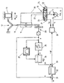
- the piston rod 10 of a hydraulic cylinder 11 moves via a knee lever assembly 12 a in a sliding joint Guided mass 13.
- the toggle lever assembly 12 is itself to a transmission with stroke-dependent translation whose Gear ratio of the position of the mass 13 dependent is.
- Such transmissions are used in injection molding machines, because their kinematic speed course favorable for closing and opening the injection molding tools.
- at the mass 13 is a tool half of a Injection mold, which is shown here only schematically is.
- the position of the mass 13 is denoted by xm.
- An in the drawing shown as a variable displacement pump 16 promotes Pressure medium from a tank 17.
- An electro-magnetically actuated hydraulic valve 18 controls the pressure medium supply to the chambers of the cylinder 11.
- An amplifier 20 sets a Control voltage ust into currents ia and ib.
- the spool of the Valve 18 is in the absence of control by springs 23 and 24 held in its middle position.
- the sign of the Control voltage ust determines whether the magnet 21 or the magnet 22 is energized.
- the amount of control voltage ust determines the size of the deflection of the spool valve Valve 18.
- the deflection of the spool determines the Opening cross section of the valve 18 and thus the speed, with the piston rod 10 on or extends. Is the Control voltage ust positive, the magnet 21 with a Current ia applied to its height by the amount of control voltage ust is determined.
- This current directs the spool of the valve 18 so that pressure fluid from the pump 16 via a line 27 into the lower chamber of the cylinder eleventh flows.
- the piston rod 10 extends and moves the mass 13th over the knee lever assembly 12 to the right. From the top Chamber of the cylinder 10, pressure medium is displaced and flows via a line 28 and the valve 18 to the tank 17 back. If the control voltage ust negative, the magnet 22 with a current ib charged, whose amount by the amount of Control voltage ust is determined. This current directs the spool of the valve 18 so that pressure fluid from the Pump 16 via line 28 into the upper chamber of the cylinder 11 flows. The piston rod 10 retracts and moves the Mass 13 on the knee lever assembly 12 to the left. From the lower chamber of the cylinder 10, pressure medium is displaced and flows via the line 27 and the valve 18 to the tank 17th back.
- An only schematically illustrated displacement sensor 30 detects the position of the piston rod 10.
- the position of the piston rod 10 is denoted by x in the following. Since there is a fixed relationship between the position xm of the mass 13 and the position x of the piston rod 10 via the toggle lever arrangement 12, it is not necessary to provide an additional displacement sensor for the position xm of the mass 13, but it suffices to determine the position x of the piston rod 10 and to calculate from this the position of the mass xm.
- a digital displacement sensor is preferably used in order to reduce the influence of noise signals superimposed on the useful signal in the temporal derivative of the position signal.
- a comparison device 31 forms the difference between a reference variable w for the position of the piston rod 10 and the position x serving as the actual position of the piston rod.
- the output signal of the comparator 31 is fed to a controller 32 with P-behavior as a control deviation.
- a logic circuit 33 superimposes an auxiliary quantity yh on the output signal y of the controller 32.
- the logic circuit 33 outputs the control voltage ust, which determines the direction and amount of the speed at which the piston rod 10 of the cylinder 11 moves.
- a differentiating element 35 forms by twice the time derivative of the position x of the piston rod 10 is a signal , which is a measure of the acceleration of the piston rod 10.
- the differentiating element 35 is followed by a P-element 36 with a controllable amplification factor.
- the amplification factor of the P-element 36 is designated KB.
- the adjustment of the gain factor KB is effected by the output signal of a function generator 37, which converts the position x of the piston rod 10 into a trapezoidal function.
- the trapezoidal function approximates the relationship between the natural frequency of the system consisting of the cylinder 11, the transmission 12 and the mass 23 to be moved and the position of the mass 13 or piston rod 10 to be moved. Unlike saving the exact profile, only four points need to be stored for the trapezoidal function. This measure leads to a significant reduction in the required storage space.
- the function generator 37 ensures that the gain factor KB is small in the regions near the end positions of the mass 13 to be moved and large in the region lying between the end positions. This means that the auxiliary quantity yh, which is subtracted from the output variable y of the controller 32, is effective only in the middle region between the end positions and then subsequently reduced to the end positions until it is virtually no longer effective in the end positions.
- the inventive method is not only in connection with a position control for the piston rod 10 - as in the figure shown - used, but also for a Control of the speed with which the piston rod 10 is moved. This is the case when the signal connection between the controller 32 and the logic circuit 33rd is separated and the logic circuit 33 instead of the Output voltage of the controller 32, an external control voltage as a measure of the speed with which the piston rod 10th the cylinder 11 is to be moved, is supplied.
- the inventive method can also be used for drives use in which the control of the cylinder supplied Pressure medium through a pure pump drive with adjustable Volumetric flow takes place, so that the throttle losses generating valve between the pump and the cylinder omitted can.
- the control of the flow rate through the delivery volume of the pump and / or by the control of Speed of the motor driving the pump can be used for drives use in which the control of the cylinder supplied Pressure medium through a pure pump drive with adjustable Volumetric flow takes place, so that the throttle losses generating valve between the pump and the cylinder omitted can.
- the process according to the invention can not only be advantageous for the regulation of the movement of toggle arrangements in plastic machines - as in the above embodiment described - but also to regulate the movement of toggle assemblies in presses.
- General is the inventive method always applicable when a mass via a transmission with stroke-dependent translation is driven by a hydraulic cylinder.
Landscapes
- Engineering & Computer Science (AREA)
- Mechanical Engineering (AREA)
- Manufacturing & Machinery (AREA)
- Physics & Mathematics (AREA)
- General Physics & Mathematics (AREA)
- Automation & Control Theory (AREA)
- Human Computer Interaction (AREA)
- General Engineering & Computer Science (AREA)
- Fluid Mechanics (AREA)
- Fluid-Pressure Circuits (AREA)
- Injection Moulding Of Plastics Or The Like (AREA)
- Crushing And Grinding (AREA)
- Apparatuses For Generation Of Mechanical Vibrations (AREA)
- Servomotors (AREA)
- Lifting Devices For Agricultural Implements (AREA)
- Control Of Transmission Device (AREA)
Claims (4)
- Un procédé d'asservissement du mouvement d'une masse, qu'un vérin hydraulique sollicité par un fluide sous pression peut déplacer et qu'une transmission dont la traduction est fonction de la position, en particulier un mécanisme à levier coudé, relie à la tige de vérin du vérin,caractérisé en ce quepour lequel l'alimentation du vérin en fluide de pression est commandée par un régulateur de position de la tige de vérin etpour lequel une grandeur auxiliaire, qui est fonction de l'accélération de la tige de vérin et qui constitue une mesure de l'accélération de la tige de vérin, est superposée à la grandeur de sortie du régulateur,
la grandeur (yh) auxiliaire est donnée par un signal (x") d'accélération, qui est pondéré en fonction de la position (xm) de la masse (13), de façon à réduire l'effet de la grandeur (yh) auxiliaire sur le processus d'asservissement dans les zones où le système constitué du vérin (11), de la transmission (12) et de la masse (13) mobile présente une fréquence propre élevée. - Un procédé selon la revendication n° 1, caractérisé en ce que le signal (x") d'accélération est multiplié par un coefficient (KB), qui dépend de la position (x) de la tige (10) de vérin.
- Un procédé selon la revendication n° 2, caractérisé en ce que la relation entre la position (x) de la tige (10) de vérin et le coefficient (KB), servant à la pondération du signal (x") d'accélération, est obtenue par approximation à l'aide d'une fonction trapézoïdale pour un mécanisme (12) à levier coudé.
- Un procédé selon une des revendications précédentes, caractérisé en ce qu'un capteur (30) de position digital est utilisé pour saisir la position (x) de la tige (10) de vérin.
Applications Claiming Priority (2)
| Application Number | Priority Date | Filing Date | Title |
|---|---|---|---|
| DE10100965A DE10100965A1 (de) | 2001-01-11 | 2001-01-11 | Verfahren zur Regelung der Bewegung einer von einem druckmittelbeaufschlagten hydraulischen Zylinder bewegbaren Masse |
| DE10100965 | 2001-01-11 |
Publications (3)
| Publication Number | Publication Date |
|---|---|
| EP1223486A2 EP1223486A2 (fr) | 2002-07-17 |
| EP1223486A3 EP1223486A3 (fr) | 2004-01-28 |
| EP1223486B1 true EP1223486B1 (fr) | 2005-08-17 |
Family
ID=7670228
Family Applications (1)
| Application Number | Title | Priority Date | Filing Date |
|---|---|---|---|
| EP01129462A Expired - Lifetime EP1223486B1 (fr) | 2001-01-11 | 2001-12-11 | Procédé pour le réglage du mouvement d'une masse qui est entrainée par un vérin hydraulique pressurisé |
Country Status (3)
| Country | Link |
|---|---|
| EP (1) | EP1223486B1 (fr) |
| AT (1) | ATE302435T1 (fr) |
| DE (2) | DE10100965A1 (fr) |
Family Cites Families (11)
| Publication number | Priority date | Publication date | Assignee | Title |
|---|---|---|---|---|
| US4502109A (en) * | 1982-09-14 | 1985-02-26 | Vickers, Incorporated | Apparatus for estimating plural system variables based upon a single measured system variable and a mathematical system model |
| DE3501568A1 (de) * | 1984-03-15 | 1985-09-19 | Mannesmann Rexroth GmbH, 8770 Lohr | Verfahren zur regelung eines anbaugeraets an landwirtschaftlichen schleppern |
| DE3642642C3 (de) * | 1986-12-13 | 1994-09-01 | Rexroth Mannesmann Gmbh | Schaltungsanordnung zur Lage- und Vorschubregelung eines hydraulischen Antriebes |
| US5218895A (en) * | 1990-06-15 | 1993-06-15 | Caterpillar Inc. | Electrohydraulic control apparatus and method |
| JP3100771B2 (ja) * | 1992-07-14 | 2000-10-23 | ナルデック株式会社 | 車両のサスペンション装置 |
| NL9201896A (nl) * | 1992-10-30 | 1994-05-16 | Fokker Aircraft | Bewegings-simulator. |
| DE4303160A1 (de) * | 1993-02-04 | 1994-08-11 | Bosch Gmbh Robert | System zur Regelung und/oder Steuerung eines Kraftfahrzeugfahrwerks |
| DE4303760C2 (de) * | 1993-02-09 | 1995-12-14 | Procontrol Ag | Verfahren und Vorrichtung zum hydraulischen Massenantrieb insbesondere von Spritzgiessmaschinen |
| KR0164653B1 (ko) * | 1994-03-18 | 1999-01-15 | 이시다 아쯔미 | 현가제어장치 |
| DE19680008C1 (de) * | 1995-05-16 | 2002-01-24 | Globemag L P | Vorrichtung mit wenigstens einem kontrollierten hydraulisch angetriebenen Aktuator |
| JPH11291312A (ja) * | 1998-04-08 | 1999-10-26 | Toyo Mach & Metal Co Ltd | トグル式型締装置の型開閉方法 |
-
2001
- 2001-01-11 DE DE10100965A patent/DE10100965A1/de not_active Withdrawn
- 2001-12-11 DE DE50107110T patent/DE50107110D1/de not_active Expired - Fee Related
- 2001-12-11 AT AT01129462T patent/ATE302435T1/de not_active IP Right Cessation
- 2001-12-11 EP EP01129462A patent/EP1223486B1/fr not_active Expired - Lifetime
Also Published As
| Publication number | Publication date |
|---|---|
| DE50107110D1 (de) | 2005-09-22 |
| ATE302435T1 (de) | 2005-09-15 |
| EP1223486A2 (fr) | 2002-07-17 |
| EP1223486A3 (fr) | 2004-01-28 |
| DE10100965A1 (de) | 2002-07-18 |
Similar Documents
| Publication | Publication Date | Title |
|---|---|---|
| EP1067319B1 (fr) | Dispositif de commande pour actionneur de transmission | |
| EP0403041B1 (fr) | Machine à mouler par injection avec des actionneurs hydrauliques | |
| EP0649722B1 (fr) | Dispositif hydraulique | |
| DE102008019501B4 (de) | Elektrohydraulische Steueranordnung | |
| EP0641644A1 (fr) | Procédé de commande d'entraînement d'une presse hydraulique et dispositif pour la mise en oeuvre du procédé | |
| DE102015114845A1 (de) | Verfahren und Gerät zum Spritzgießen von Kunststoffmaterialien | |
| DE3413665A1 (de) | Verfahren zur steuerung der spritzgeschwindigkeit eines spritzgusszylinders einer spritzgussmaschine | |
| DE4335328A1 (de) | Hydraulisches Betriebssystem für Spritzgießmaschinen | |
| AT509617B1 (de) | Hydraulische antriebseinheit für eine spritzgiessmaschine | |
| EP4281282B1 (fr) | Machine de formage hydraulique destinée à comprimer des pièces, en particulier marteau à forger, et procédé pour faire fonctionner une machine de formage hydraulique, en particulier un marteau à forger | |
| WO2018210448A2 (fr) | Procédé de fonctionnement d'une presse à poudre à régulation de position et presse à poudre pour mettre en œuvre le procédé | |
| EP1355775B1 (fr) | Procede de regulation d'assistance hydraulique d'une commande electrique | |
| DE4327313C2 (de) | Verfahren zur Druckregelung einer hydrostatischen Maschine mit verstellbarem Fördervolumen | |
| DE4313597B4 (de) | Verfahren zum Betreiben einer verstellbaren hydrostatischen Pumpe und dafür ausgebildetes hydrostatisches Antriebssystem | |
| EP1223486B1 (fr) | Procédé pour le réglage du mouvement d'une masse qui est entrainée par un vérin hydraulique pressurisé | |
| DE10308289B4 (de) | LS-Wegeventilblock | |
| DE102016214708A1 (de) | Stetigventileinheit, hydraulische Achse und Verfahren zum Betreiben einer hydraulischen Achse | |
| DE3331648A1 (de) | Einrichtung zur steuerung eines antriebes fuer die bewegung von werkzeugen, insbesondere von formteilen einer spritzgussmaschine | |
| DE19616383B4 (de) | Verfahren und Vorrichtung zum Steuern der Einspritzgeschwindigkeit von Spritzgießmaschinen | |
| DE2532429C3 (de) | Verfahren und Einrichtung zum Spritzgießen einer Kunststoffmasse mit veränderbarer Einspritzgeschwindigkeit | |
| WO2021228482A1 (fr) | Procédé de commande d'un système partiellement électronique | |
| AT514232B1 (de) | Verfahren zum Steuern oder Regeln einer Spritzgießmaschine | |
| DE102006028094A1 (de) | Einrichtung zum regeln einer Spritzgießmaschine | |
| DE4219787C1 (de) | Fahrzeug mit batterie-elektrischem Fahr-Antrieb, insbesondere Hublader | |
| DE4031808A1 (de) | Anordnung zur ansteuerung eines stellmotors sowie verfahren zur ansteuerung eines stellmotors |
Legal Events
| Date | Code | Title | Description |
|---|---|---|---|
| PUAI | Public reference made under article 153(3) epc to a published international application that has entered the european phase |
Free format text: ORIGINAL CODE: 0009012 |
|
| AK | Designated contracting states |
Kind code of ref document: A2 Designated state(s): AT BE CH CY DE DK ES FI FR GB GR IE IT LI LU MC NL PT SE TR |
|
| AX | Request for extension of the european patent |
Free format text: AL;LT;LV;MK;RO;SI |
|
| RAP1 | Party data changed (applicant data changed or rights of an application transferred) |
Owner name: BOSCH REXROTH AG |
|
| PUAL | Search report despatched |
Free format text: ORIGINAL CODE: 0009013 |
|
| AK | Designated contracting states |
Kind code of ref document: A3 Designated state(s): AT BE CH CY DE DK ES FI FR GB GR IE IT LI LU MC NL PT SE TR |
|
| AX | Request for extension of the european patent |
Extension state: AL LT LV MK RO SI |
|
| 17P | Request for examination filed |
Effective date: 20040327 |
|
| AKX | Designation fees paid |
Designated state(s): AT CH DE IT LI |
|
| GRAP | Despatch of communication of intention to grant a patent |
Free format text: ORIGINAL CODE: EPIDOSNIGR1 |
|
| GRAS | Grant fee paid |
Free format text: ORIGINAL CODE: EPIDOSNIGR3 |
|
| GRAA | (expected) grant |
Free format text: ORIGINAL CODE: 0009210 |
|
| AK | Designated contracting states |
Kind code of ref document: B1 Designated state(s): AT CH DE IT LI |
|
| REG | Reference to a national code |
Ref country code: CH Ref legal event code: EP |
|
| REF | Corresponds to: |
Ref document number: 50107110 Country of ref document: DE Date of ref document: 20050922 Kind code of ref document: P |
|
| REG | Reference to a national code |
Ref country code: CH Ref legal event code: NV Representative=s name: SCINTILLA AG, DIREKTION |
|
| PLBE | No opposition filed within time limit |
Free format text: ORIGINAL CODE: 0009261 |
|
| STAA | Information on the status of an ep patent application or granted ep patent |
Free format text: STATUS: NO OPPOSITION FILED WITHIN TIME LIMIT |
|
| 26N | No opposition filed |
Effective date: 20060518 |
|
| PGFP | Annual fee paid to national office [announced via postgrant information from national office to epo] |
Ref country code: IT Payment date: 20071222 Year of fee payment: 7 Ref country code: CH Payment date: 20071219 Year of fee payment: 7 Ref country code: AT Payment date: 20071220 Year of fee payment: 7 |
|
| PGFP | Annual fee paid to national office [announced via postgrant information from national office to epo] |
Ref country code: DE Payment date: 20080226 Year of fee payment: 7 |
|
| REG | Reference to a national code |
Ref country code: CH Ref legal event code: PL |
|
| PG25 | Lapsed in a contracting state [announced via postgrant information from national office to epo] |
Ref country code: AT Free format text: LAPSE BECAUSE OF NON-PAYMENT OF DUE FEES Effective date: 20081211 |
|
| PG25 | Lapsed in a contracting state [announced via postgrant information from national office to epo] |
Ref country code: CH Free format text: LAPSE BECAUSE OF NON-PAYMENT OF DUE FEES Effective date: 20081231 Ref country code: DE Free format text: LAPSE BECAUSE OF NON-PAYMENT OF DUE FEES Effective date: 20090701 Ref country code: LI Free format text: LAPSE BECAUSE OF NON-PAYMENT OF DUE FEES Effective date: 20081231 |
|
| PG25 | Lapsed in a contracting state [announced via postgrant information from national office to epo] |
Ref country code: IT Free format text: LAPSE BECAUSE OF NON-PAYMENT OF DUE FEES Effective date: 20081211 |