EP1225300B1 - Gesteinsbohrer - Google Patents
Gesteinsbohrer Download PDFInfo
- Publication number
- EP1225300B1 EP1225300B1 EP02405004A EP02405004A EP1225300B1 EP 1225300 B1 EP1225300 B1 EP 1225300B1 EP 02405004 A EP02405004 A EP 02405004A EP 02405004 A EP02405004 A EP 02405004A EP 1225300 B1 EP1225300 B1 EP 1225300B1
- Authority
- EP
- European Patent Office
- Prior art keywords
- edge
- rock drill
- drill bit
- minor
- cutting edge
- Prior art date
- Legal status (The legal status is an assumption and is not a legal conclusion. Google has not performed a legal analysis and makes no representation as to the accuracy of the status listed.)
- Expired - Lifetime
Links
- 239000011435 rock Substances 0.000 title claims description 17
- 230000001154 acute effect Effects 0.000 claims description 3
- 239000007787 solid Substances 0.000 description 9
- 238000005553 drilling Methods 0.000 description 5
- XEEYBQQBJWHFJM-UHFFFAOYSA-N Iron Chemical compound [Fe] XEEYBQQBJWHFJM-UHFFFAOYSA-N 0.000 description 4
- 239000000463 material Substances 0.000 description 3
- 229910052742 iron Inorganic materials 0.000 description 2
- 230000003014 reinforcing effect Effects 0.000 description 2
- 235000002505 Centaurea nigra Nutrition 0.000 description 1
- 241001073742 Mylopharodon conocephalus Species 0.000 description 1
- 238000011161 development Methods 0.000 description 1
- 230000018109 developmental process Effects 0.000 description 1
- 238000011010 flushing procedure Methods 0.000 description 1
Images
Classifications
-
- E—FIXED CONSTRUCTIONS
- E21—EARTH OR ROCK DRILLING; MINING
- E21B—EARTH OR ROCK DRILLING; OBTAINING OIL, GAS, WATER, SOLUBLE OR MELTABLE MATERIALS OR A SLURRY OF MINERALS FROM WELLS
- E21B10/00—Drill bits
- E21B10/46—Drill bits characterised by wear resisting parts, e.g. diamond inserts
- E21B10/58—Chisel-type inserts
Definitions
- the invention refers to a rock drill, at least partially rotating and hammering driven by a hand tool device, for the abrasive removal of rock and rock-like material, such as concrete.
- Rock drills for hand tools have at one end of the shaft a spigot and at the other end a tool head with cutting edges of hard material.
- the tool head has to cutting inserts or cutting bits made of hard material or is designed as a compact Vollhartstoffkopf.
- a disadvantage is the increased stress on the cutting edge in the case of reinforcing iron hits in the concrete, in particular in designs with an acute wedge angle suitable for high drilling capacities.
- a drill bit provided with flushing bores has two radially offset secondary cutting plates arranged parallel to one another relative to the secondary cutting edge with respect to the secondary cutting edge.
- auxiliary cutting plates are spaced radially different from the main cutting plate.
- a rock drill for hand tools with compact solid hard head on a diametrically extending main cutting edge and arranged exclusively in the radially outer region, with respect to the direction of rotation trailing angled, minor cutting edges whose secondary cutting edge extends radially. Due to the faster wear of the axially projecting main cutting edge reduces the axial board, which reduces the drilling performance and the life.
- the object of the invention is to reduce the risk of breakage of solid carbide head at Arm michsseisentreffern. Another aspect is an increase in the lifetime.
- EP 0 965 405, DE 4 012 772 and EP 1 045 112, on which the preamble of claim 1 is based, disclose secondary cutting edges that run in a radially arcuate manner.
- the solid carbide head of a rock drill for hand tools has a main cutting edge and at least one secondary cutting edge arranged radially exclusively in the outer region, with an arcuate secondary cutting edge.
- the arcuate secondary cutting edge of the sheath circumferentially performed axially rounded, which is lifted axially at a Arm michsseisen Economics the rock drill at this minor cutting edge and the two-sided cutting surfaces.
- the solid carbide head on two minor cutting edges, which are further advantageously arranged symmetrically to the main cutting edge, whereby the vibration noise can be reduced.
- the main cutting edge on two diametrically offset cutting edges which converge as a tip in a roof edge, resulting in a stable Anbohr .
- the secondary cutting edges are advantageously set back axially behind the envelope of the main cutting edges, as a result of which the drilling power increases due to a higher force on the main cutting edge.
- the secondary cutting edges form a sharp wedge angle between 50 ° and 80 ° in the radial plane, as a result of which the secondary cutting edges can penetrate aggressively into hard ground and increase the drilling capacity.
- the secondary cutting edges with respect to the length of their arcuate secondary cutting edge (4a, 4b) are formed such that they are worn axially in the same mass as the main cutting, which over a long service life, a high drilling performance is achieved.
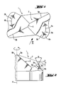
- the solid solid head 1, shown in plan view, of a rock drill for handheld power tools not shown further comprises a main cutting edge 2 and two diametrically offset, symmetrically to the main cutting edge 2, radially outermost in the outer region, arranged minor cutting edges 3a, 3b, each with an arcuate, circumferential axially rounded secondary cutting edge 4a, 4b.
- the main cutting edge 2 has two cutting edges 5a, 5b, which converge as a tip of the rock drill in a roof edge 6.
- the secondary cutting edges 3a, 3b each have an arcuate arc length of approximately ⁇ / 4 rad.
Landscapes
- Engineering & Computer Science (AREA)
- Geology (AREA)
- Life Sciences & Earth Sciences (AREA)
- Mining & Mineral Resources (AREA)
- Physics & Mathematics (AREA)
- Environmental & Geological Engineering (AREA)
- Fluid Mechanics (AREA)
- Mechanical Engineering (AREA)
- General Life Sciences & Earth Sciences (AREA)
- Geochemistry & Mineralogy (AREA)
- Earth Drilling (AREA)
- Processing Of Stones Or Stones Resemblance Materials (AREA)
- Drilling Tools (AREA)
- Drilling And Exploitation, And Mining Machines And Methods (AREA)
Description
- Die Erfindung bezeichnet einen zumindest teilweise drehend und schlagend von einem Handwerkzeuggerät angetriebenen Gesteinsbohrer zum abrasiven Abtrag von Gestein und gesteinsähnlichem Material wie Beton.
- Gesteinsbohrer für Handwerkzeuggeräte weisen an einem Ende des Schafts ein Einsteckende und am anderen Ende einen Werkzeugkopf mit Schneiden aus Hartstoff auf. Der Werkzeugkopf weist dazu Schneidplatten oder Schneidbits aus Hartstoff auf oder ist als kompakter Vollhartstoffkopf ausgeführt. Nachteilig ist die bei Armierungseisentreffern im Beton erhöhte Beanspruchung der Schneidkante, insbesondere bei Ausbildungen mit einem für hohe Bohrleistungen geeigneten spitzen Keilwinkel.
- Nach der GB530113A weist ein mit Spülbohrungen versehener Werkzeugkopf eines Gesteinsbohrers zwei zu einer Hauptschneidplatte, bezüglich der Nebenschneidkante parallel orientierte, radial versetzte Nebenschneidplatten auf.
- Nach der EP607958A1 sind bei einem Gesteinsbohrer für Handwerkzeuggeräte zwei, bezüglich der Nebenschneidkante parallel orientierte, Nebenschneidplatten unterschiedlich radial zur Hauptschneidplatte beabstandet.
- Nach der US5492187 weist ein Gesteinsbohrer für Handwerkzeuggeräte mit kompaktem Vollhartstoffkopf eine diametral verlaufende Hauptschneide und ausschliesslich im radial äusseren Bereich angeordnete, bezüglich der Drehrichtung spitzwinkelig nachlaufende, Nebenschneiden auf, deren Nebenschneidkante sich radial erstreckt. Durch den schnelleren Verschleiss der axial vorstehenden Hauptschneide verringert sich deren axialer Vorstand, wodurch sich die Bohrleistung bzw. die Lebensdauer reduziert.
- Die Aufgabe der Erfindung besteht in der Verringerung der Bruchgefahr des Vollhartstoffkopfes bei Armierungseisentreffern. Ein weiterer Aspekt besteht in einer Erhöhung der Lebensdauer.
- Die EP 0 965 405, DE 4 012 772 und die EP1 045 112, auf der des Oberbegiff von Anspruch 1 basiert, offenbaren jeweils Nebenschneidkanten, die radial bogenförmig verlaufen.
- Die Aufgabe wird im wesentlichen durch die Merkmale der unabhängigen Ansprüche gelöst. Vorteilhafte Weiterbildungen ergeben sich aus den Unteransprüchen.
- Im wesentlichen weist der Vollhartstoffkopf eines Gesteinsbohrers für Handwerkzeuggeräte eine Hauptschneide und zumindest eine radial ausschliesslich im äusseren Bereich angeordnete Nebenschneide mit einer bogenförmig verlaufenden Nebenschneidkante auf.
- Durch die bogenförmig verlaufende Nebenschneidkante der Nebenschneide ist diese in der bei Armierungseisentreffern hauptsächlich beanspruchten tangentialen Richtung länglich ausgeführt und weist somit bei Armierungseisentreffern eine hohe Beanspruchbarkeit und Lebensdauer auf.
- Vorteilhaft ist die bogenförmig verlaufende Nebenschneidkante der Nebenscheide umfänglich axial abgerundet ausgeführt, wodurch bei einem Armierungseisentreffer der Gesteinsbohrer an dieser Nebenschneidkante und den beidseitigen Schneidflächen axial abgehoben wird.
- Vorteilhaft weist der Vollhartstoffkopf zwei Nebenschneiden auf, die weiter vorteilhaft symmetrisch zur Hauptschneide angeordnet sind, wodurch die Vibrationsgeräusche reduziert werden.
- Vorteilhaft weist die Hauptschneide zwei diametral versetzte Schneidkanten auf, welche als Spitze in einer Dachkante zusammenlaufen, wodurch sich ein stabiles Anbohrverhalten ergibt.
- Vorteilhaft sind die Nebenschneiden axial hinter die Hüllkurve der Hauptschneiden zurückgesetzt, wodurch sich durch eine höhere Kraft auf die Hauptschneide die Bohrleistung erhöht.
- Vorteilhaft bilden die Nebenschneiden in der radialen Ebene einen spitzen Keilwinkel zwischen 50° und 80° aus, wodurch die Nebenschneiden aggressiv in harten Untergrund eindringen können und die Bohrleistung erhöhen.
- Vorteilhaft sind die Nebenschneiden bezüglich der Länge ihrer bogenförmig verlaufenden Nebenschneidkante (4a, 4b) derart ausgebildet, dass sie im gleichen Masse wie die Hauptschneiden axial verschlissen werden, wodurch über eine hohe Lebensdauer eine hohe Bohrleistung erzielt wird.
- Die Erfindung wird bezüglich eines vorteilhaften Ausführungsbeispiels näher erläutert mit
- Fig. 1 als Aufsicht des Vollhartstoffkopfes
- Fig. 2 als Seitenansicht eines Teils des Vollhartstoffkopfes
- Nach der Fig. 1 weist der in Aufsicht dargestellte Vollhartstoffkopf 1 eines nicht weiter dargestellten Gesteinsbohrers für Handwerkzeuggeräte eine Hauptschneide 2 und zwei diametral versetzte, symmetrisch zur Hauptschneide 2, radial ausschliesslich im äusseren Bereich, angeordnete Nebenschneiden 3a, 3b mit je einer bogenförmig verlaufenden, umfänglich axial abgerundeten Nebenschneidkante 4a, 4b auf. Die Hauptschneide 2 weist zwei Schneidkanten 5a, 5b auf, welche als Spitze des Gesteinsbohrers in einer Dachkante 6 zusammenlaufen. Die Nebenschneiden 3a, 3b weisen je eine bogenförmige Bogenlänge von ca. π/4 rad auf.
- Nach Fig. 2 weist der in Seitenansicht dargestellte Teil des Vollhartstoffkopfes 1 eines nicht weiter dargestellten Gesteinsbohrers für Handwerkzeuggeräte eine axial zur Drehachse A um den Nebenschneidenrückstand x hinter die Hüllkurve 7 der Hauptschneide 2 zurückgesetzte Nebenschneide 3a auf, welche in der radialen Ebene quer zur Nebenschneidkante 4a einen spitzen Keilwinkel α von 65° zu den beidseitigen, teilweise konkav geformten, Schneidflächen 8a, 8b ausbilden.
Claims (6)
- Gesteinsbohrer für Handwerkzeuggeräte mit einem Vollhartstoffkopf (1) mit einer Hauptschneide (2) und zumindest einer radial ausschliesslich im äusseren Bereich angeordneten Nebenschneide (3a, 3b), dadurch gekennzeichnet, dass die Nebenschneide (3a, 3b) eine in tangentialer Richtung länglich bogenförmig verlaufende Nebenschneidkante (4a, 4b) aufweist.
- Gesteinsbohrer nach Anspruch 1, dadurch gekennzeichnet, dass die bogenförmig verlaufende Nebenschneidkante (4a, 4b) der Nebenscheide (3a, 3b) umfänglich axial abgerundet ausgeführt ist.
- Gesteinsbohrer nach Anspruch 1 oder Anspruch 2, dadurch gekennzeichnet, dass die Hauptschneide (2) zwei diametral versetzte Schneidkanten (5a, 5b) aufweist, welche optional als Spitze in einer Dachkante (6) zusammenlaufen.
- Gesteinsbohrer nach einem der vorherigen Ansprüche, dadurch gekennzeichnet, dass die Nebenschneide (3a, 3b) axial hinter die Hüllkurve (7) der Hauptschneide (2) zurückgesetzt ist.
- Gesteinsbohrer nach einem der vorherigen Ansprüche, dadurch gekennzeichnet, dass die Nebenschneide (3a, 3b) in der radialen Ebene einen spitzen Keilwinkel (α) zwischen 50° und 80° ausbildet.
- Gesteinsbohrer nach einem der vorherigen Ansprüche, dadurch gekennzeichnet, dass die Nebenschneide (3a, 3b) mit der Länge ihrer bogenförmig verlaufenden Nebenschneidkante (4a, 4b) auf einen, mit der Hauptschneide (2) gleichmassigen, axialen Verschleiss abstimmbar ist.
Applications Claiming Priority (2)
| Application Number | Priority Date | Filing Date | Title |
|---|---|---|---|
| DE10117262A DE10117262A1 (de) | 2001-01-17 | 2001-01-17 | Gesteinsbohrer |
| DE10117262 | 2001-01-17 |
Publications (3)
| Publication Number | Publication Date |
|---|---|
| EP1225300A2 EP1225300A2 (de) | 2002-07-24 |
| EP1225300A3 EP1225300A3 (de) | 2003-11-19 |
| EP1225300B1 true EP1225300B1 (de) | 2006-05-10 |
Family
ID=7680683
Family Applications (1)
| Application Number | Title | Priority Date | Filing Date |
|---|---|---|---|
| EP02405004A Expired - Lifetime EP1225300B1 (de) | 2001-01-17 | 2002-01-08 | Gesteinsbohrer |
Country Status (4)
| Country | Link |
|---|---|
| US (1) | US6843334B2 (de) |
| EP (1) | EP1225300B1 (de) |
| JP (1) | JP3921089B2 (de) |
| DE (2) | DE10117262A1 (de) |
Families Citing this family (16)
| Publication number | Priority date | Publication date | Assignee | Title |
|---|---|---|---|---|
| UA77084C2 (en) * | 2002-06-06 | 2006-10-16 | Miyanaga Kk | Drill bit |
| US6883624B2 (en) * | 2003-01-31 | 2005-04-26 | Smith International, Inc. | Multi-lobed cutter element for drill bit |
| ATE367906T1 (de) * | 2003-11-17 | 2007-08-15 | Bosch Gmbh Robert | Bohr- und/oder meisselwerkzeug |
| US7690442B2 (en) * | 2005-05-17 | 2010-04-06 | Smith International, Inc. | Drill bit and cutting inserts for hard/abrasive formations |
| US7624825B2 (en) * | 2005-10-18 | 2009-12-01 | Smith International, Inc. | Drill bit and cutter element having aggressive leading side |
| DE102006000083A1 (de) * | 2006-02-20 | 2007-08-23 | Hilti Ag | Ankerbohrkopf |
| DE102006020538A1 (de) * | 2006-05-03 | 2007-11-15 | Irwin Industrial Tools Gmbh | Bohrkopf für Bohrwerkzeug und Bohrwerkzeug |
| DE102006000221A1 (de) * | 2006-05-10 | 2007-11-15 | Hilti Ag | Hartstoffbohrkopf |
| US7743855B2 (en) * | 2006-09-05 | 2010-06-29 | Smith International, Inc. | Drill bit with cutter element having multifaceted, slanted top cutting surface |
| DE502006002391D1 (de) | 2006-09-26 | 2009-01-29 | Baero Gmbh & Co Kg | Beleuchtungsanlage |
| DE102007000534A1 (de) * | 2007-10-19 | 2009-04-23 | Hilti Aktiengesellschaft | Schlagbohrwerkzeug |
| DE202008014317U1 (de) | 2008-10-28 | 2009-01-29 | BÄRO GmbH & Co. KG | Leuchte |
| US7861807B2 (en) * | 2008-12-03 | 2011-01-04 | Black & Decker Inc. | Drill bit including one piece cutting head |
| US20140182947A1 (en) | 2012-12-28 | 2014-07-03 | Smith International, Inc. | Cutting insert for percussion drill bit |
| WO2017123562A1 (en) | 2016-01-13 | 2017-07-20 | Schlumberger Technology Corporation | Angled chisel insert |
| EP4375476A1 (de) * | 2022-11-22 | 2024-05-29 | Hilti Aktiengesellschaft | Gesteinsbohrer mit fünf schneiden |
Family Cites Families (22)
| Publication number | Priority date | Publication date | Assignee | Title |
|---|---|---|---|---|
| DE1812229A1 (de) * | 1968-12-02 | 1971-01-14 | Hilti Ag | Bohrer bzw. Bohrerhalter fuer Bohrhaemmer |
| US3647310A (en) * | 1970-04-03 | 1972-03-07 | Mansfield K Morse | Universal hole saw arbor |
| DE2129913A1 (de) * | 1971-06-16 | 1972-12-21 | Hilti Ag | Gesteinsbohrer |
| DE2414354A1 (de) * | 1974-03-26 | 1975-10-16 | Heller Geb | Gesteinsbohrer |
| DE2807156C2 (de) * | 1978-02-20 | 1986-11-20 | Gebrüder Heller Verwaltungsgesellschaft mbH, 2807 Achim | Gesteinsbohrwerkzeug |
| DE3426977A1 (de) * | 1984-07-21 | 1986-01-30 | Hawera Probst Gmbh + Co, 7980 Ravensburg | Gesteinsbohrer |
| JP2534676Y2 (ja) | 1989-04-24 | 1997-05-07 | 仁 下城 | 無蓋型乗用車 |
| DE4012772A1 (de) * | 1990-04-21 | 1991-10-24 | Westa Werkzeugbau | Bohrer fuer bohrhaemmer, insbesondere zum bohren im gestein, beton o. dgl. |
| US5273380A (en) | 1992-07-31 | 1993-12-28 | Musacchia James E | Drill bit point |
| DE4339245A1 (de) * | 1993-11-18 | 1995-05-24 | Hilti Ag | Spiralbohrer |
| US5466099A (en) * | 1993-12-13 | 1995-11-14 | Tdw Delaware, Inc. | Cutter shell for forming holes of improved cylindricality |
| DE4436917A1 (de) * | 1994-10-15 | 1996-04-18 | Hilti Ag | Bohreinheit mit Hohlbohrkrone und Zentrierdorn |
| DE19545647A1 (de) * | 1995-12-07 | 1997-06-12 | Hilti Ag | Drehschlag-Wendelbohrer |
| DE19650487A1 (de) * | 1996-12-05 | 1998-06-10 | Hilti Ag | Bohrwerkzeug |
| DE19711261A1 (de) * | 1997-03-18 | 1998-09-24 | Hilti Ag | Kombi-Bohrwerkzeug |
| DE19724373A1 (de) * | 1997-06-10 | 1998-12-17 | Hilti Ag | Gesteinsbohrer |
| DE19740277B4 (de) * | 1997-09-13 | 2012-05-24 | Robert Bosch Gmbh | Bohrwerkzeug |
| DE19748987B4 (de) * | 1997-11-06 | 2007-11-22 | Robert Bosch Gmbh | Bohrwerkzeug insbesondere für drehschlagendes Bohren von vorzugsweise Gestein |
| DE19827536A1 (de) * | 1998-06-20 | 1999-12-23 | Hilti Ag | Bohrwerkzeug |
| DE19916975A1 (de) | 1999-04-15 | 2000-10-19 | Hilti Ag | Gesteinsbohrer |
| DE10006936A1 (de) * | 2000-02-16 | 2001-08-23 | Hilti Ag | Bohrwerkzeug für Gestein |
| DE10006932A1 (de) * | 2000-02-16 | 2001-08-23 | Hilti Ag | Bohrwerkzeug für Gestein |
-
2001
- 2001-01-17 DE DE10117262A patent/DE10117262A1/de not_active Withdrawn
-
2002
- 2002-01-08 DE DE50206710T patent/DE50206710D1/de not_active Expired - Lifetime
- 2002-01-08 EP EP02405004A patent/EP1225300B1/de not_active Expired - Lifetime
- 2002-01-16 JP JP2002006989A patent/JP3921089B2/ja not_active Expired - Lifetime
- 2002-01-16 US US10/050,223 patent/US6843334B2/en not_active Expired - Lifetime
Also Published As
| Publication number | Publication date |
|---|---|
| EP1225300A2 (de) | 2002-07-24 |
| JP3921089B2 (ja) | 2007-05-30 |
| JP2002273723A (ja) | 2002-09-25 |
| EP1225300A3 (de) | 2003-11-19 |
| US6843334B2 (en) | 2005-01-18 |
| US20020108789A1 (en) | 2002-08-15 |
| DE50206710D1 (de) | 2006-06-14 |
| DE10117262A1 (de) | 2002-07-18 |
Similar Documents
| Publication | Publication Date | Title |
|---|---|---|
| EP1125664B1 (de) | Bohrwerkzeug für Gestein | |
| EP1125663B1 (de) | Bohrwerkzeug für Gestein | |
| US7658136B2 (en) | Hole saw blade | |
| EP1225300A2 (de) | Gesteinsbohrer | |
| EP0846835B1 (de) | Beton- oder Gesteinbohrwerkzeug mit wendelförmigen Abfuhrnuten | |
| US6817428B1 (en) | Drill bit | |
| US5779403A (en) | Percussive blow assisted rotary drill | |
| DE19545648A1 (de) | Drehschlag-Wendelbohrer | |
| EP1045112A1 (de) | Gesteinsbohrer | |
| EP1559492A1 (de) | Bohrmeissel | |
| US7559383B2 (en) | Hard material drilling head | |
| EP1197630B1 (de) | Wendelbohrer für Gestein | |
| DE10232214C1 (de) | Betonbohrer | |
| AU2004222834B2 (en) | Rotary hammerdrill bit | |
| EP1083295A1 (de) | Bohrwerkzeug | |
| EP1923159A1 (de) | Bohrwerkzeug mit Hartstoffkopf | |
| EP1184535A2 (de) | Gesteinsbohrer | |
| US20050025595A1 (en) | Cutting plate for a drill bit | |
| DE10054850B4 (de) | Bohrer für Gestein | |
| EP1875032B1 (de) | Bohrwerkzeug | |
| EP1923158B1 (de) | Bohrwerkzeug mit Hartstoffeinsatz | |
| DE102012015371A1 (de) | Bohrkopf für einen Bohrer und Bohrer |
Legal Events
| Date | Code | Title | Description |
|---|---|---|---|
| PUAI | Public reference made under article 153(3) epc to a published international application that has entered the european phase |
Free format text: ORIGINAL CODE: 0009012 |
|
| AK | Designated contracting states |
Kind code of ref document: A2 Designated state(s): AT BE CH CY DE DK ES FI FR GB GR IE IT LI LU MC NL PT SE TR |
|
| AX | Request for extension of the european patent |
Free format text: AL;LT;LV;MK;RO;SI |
|
| PUAL | Search report despatched |
Free format text: ORIGINAL CODE: 0009013 |
|
| AK | Designated contracting states |
Kind code of ref document: A3 Designated state(s): AT BE CH CY DE DK ES FI FR GB GR IE IT LI LU MC NL PT SE TR |
|
| AX | Request for extension of the european patent |
Extension state: AL LT LV MK RO SI |
|
| RIC1 | Information provided on ipc code assigned before grant |
Ipc: 7B 23B 51/00 B Ipc: 7E 21B 10/58 A |
|
| 17P | Request for examination filed |
Effective date: 20040519 |
|
| AKX | Designation fees paid |
Designated state(s): CH DE FR GB LI NL |
|
| GRAP | Despatch of communication of intention to grant a patent |
Free format text: ORIGINAL CODE: EPIDOSNIGR1 |
|
| RIN1 | Information on inventor provided before grant (corrected) |
Inventor name: SCHAUTT, MARTIN |
|
| GRAS | Grant fee paid |
Free format text: ORIGINAL CODE: EPIDOSNIGR3 |
|
| GRAA | (expected) grant |
Free format text: ORIGINAL CODE: 0009210 |
|
| AK | Designated contracting states |
Kind code of ref document: B1 Designated state(s): CH DE FR GB LI NL |
|
| REG | Reference to a national code |
Ref country code: GB Ref legal event code: FG4D Free format text: NOT ENGLISH |
|
| RIN1 | Information on inventor provided before grant (corrected) |
Inventor name: SCHAUTT, MARTIN |
|
| REG | Reference to a national code |
Ref country code: CH Ref legal event code: EP |
|
| REF | Corresponds to: |
Ref document number: 50206710 Country of ref document: DE Date of ref document: 20060614 Kind code of ref document: P |
|
| GBT | Gb: translation of ep patent filed (gb section 77(6)(a)/1977) |
Effective date: 20060612 |
|
| ET | Fr: translation filed | ||
| PLBE | No opposition filed within time limit |
Free format text: ORIGINAL CODE: 0009261 |
|
| STAA | Information on the status of an ep patent application or granted ep patent |
Free format text: STATUS: NO OPPOSITION FILED WITHIN TIME LIMIT |
|
| 26N | No opposition filed |
Effective date: 20070213 |
|
| PGFP | Annual fee paid to national office [announced via postgrant information from national office to epo] |
Ref country code: NL Payment date: 20090104 Year of fee payment: 8 |
|
| PGFP | Annual fee paid to national office [announced via postgrant information from national office to epo] |
Ref country code: CH Payment date: 20090114 Year of fee payment: 8 |
|
| REG | Reference to a national code |
Ref country code: NL Ref legal event code: V1 Effective date: 20100801 |
|
| REG | Reference to a national code |
Ref country code: CH Ref legal event code: PL |
|
| PG25 | Lapsed in a contracting state [announced via postgrant information from national office to epo] |
Ref country code: CH Free format text: LAPSE BECAUSE OF NON-PAYMENT OF DUE FEES Effective date: 20100131 Ref country code: NL Free format text: LAPSE BECAUSE OF NON-PAYMENT OF DUE FEES Effective date: 20100801 Ref country code: LI Free format text: LAPSE BECAUSE OF NON-PAYMENT OF DUE FEES Effective date: 20100131 |
|
| REG | Reference to a national code |
Ref country code: FR Ref legal event code: PLFP Year of fee payment: 15 |
|
| REG | Reference to a national code |
Ref country code: FR Ref legal event code: PLFP Year of fee payment: 16 |
|
| REG | Reference to a national code |
Ref country code: FR Ref legal event code: PLFP Year of fee payment: 17 |
|
| PGFP | Annual fee paid to national office [announced via postgrant information from national office to epo] |
Ref country code: FR Payment date: 20210121 Year of fee payment: 20 |
|
| PGFP | Annual fee paid to national office [announced via postgrant information from national office to epo] |
Ref country code: GB Payment date: 20210121 Year of fee payment: 20 Ref country code: DE Payment date: 20210120 Year of fee payment: 20 |
|
| REG | Reference to a national code |
Ref country code: DE Ref legal event code: R071 Ref document number: 50206710 Country of ref document: DE |
|
| REG | Reference to a national code |
Ref country code: GB Ref legal event code: PE20 Expiry date: 20220107 |
|
| PG25 | Lapsed in a contracting state [announced via postgrant information from national office to epo] |
Ref country code: GB Free format text: LAPSE BECAUSE OF EXPIRATION OF PROTECTION Effective date: 20220107 |