EP1225418A1 - Improvements to mecanotronic fuses for hand grenades - Google Patents
Improvements to mecanotronic fuses for hand grenades Download PDFInfo
- Publication number
- EP1225418A1 EP1225418A1 EP00942152A EP00942152A EP1225418A1 EP 1225418 A1 EP1225418 A1 EP 1225418A1 EP 00942152 A EP00942152 A EP 00942152A EP 00942152 A EP00942152 A EP 00942152A EP 1225418 A1 EP1225418 A1 EP 1225418A1
- Authority
- EP
- European Patent Office
- Prior art keywords
- detonator
- multiplier
- electro
- electronic
- hand grenades
- Prior art date
- Legal status (The legal status is an assumption and is not a legal conclusion. Google has not performed a legal analysis and makes no representation as to the accuracy of the status listed.)
- Granted
Links
- 230000006872 improvement Effects 0.000 title claims abstract description 16
- 239000002360 explosive Substances 0.000 claims abstract description 22
- 238000005474 detonation Methods 0.000 claims abstract description 5
- 238000006073 displacement reaction Methods 0.000 claims abstract description 3
- 230000004913 activation Effects 0.000 claims abstract 2
- 238000004880 explosion Methods 0.000 claims description 6
- 230000000977 initiatory effect Effects 0.000 claims description 5
- 238000005516 engineering process Methods 0.000 abstract description 4
- 230000000284 resting effect Effects 0.000 abstract description 3
- 230000033001 locomotion Effects 0.000 description 5
- 239000003990 capacitor Substances 0.000 description 4
- 238000010586 diagram Methods 0.000 description 3
- 239000007789 gas Substances 0.000 description 3
- 230000004048 modification Effects 0.000 description 3
- 238000012986 modification Methods 0.000 description 3
- 230000005540 biological transmission Effects 0.000 description 2
- 230000007246 mechanism Effects 0.000 description 2
- 230000009471 action Effects 0.000 description 1
- 239000003795 chemical substances by application Substances 0.000 description 1
- 230000005611 electricity Effects 0.000 description 1
- 230000005670 electromagnetic radiation Effects 0.000 description 1
- 230000007257 malfunction Effects 0.000 description 1
- 238000004137 mechanical activation Methods 0.000 description 1
- 238000000034 method Methods 0.000 description 1
- 230000008569 process Effects 0.000 description 1
- 230000005855 radiation Effects 0.000 description 1
- 238000009877 rendering Methods 0.000 description 1
Images


Classifications
-
- F—MECHANICAL ENGINEERING; LIGHTING; HEATING; WEAPONS; BLASTING
- F42—AMMUNITION; BLASTING
- F42C—AMMUNITION FUZES; ARMING OR SAFETY MEANS THEREFOR
- F42C11/00—Electric fuzes
- F42C11/06—Electric fuzes with time delay by electric circuitry
-
- F—MECHANICAL ENGINEERING; LIGHTING; HEATING; WEAPONS; BLASTING
- F42—AMMUNITION; BLASTING
- F42C—AMMUNITION FUZES; ARMING OR SAFETY MEANS THEREFOR
- F42C11/00—Electric fuzes
- F42C11/001—Electric circuits for fuzes characterised by the ammunition class or type
- F42C11/003—Electric circuits for fuzes characterised by the ammunition class or type for hand grenades
-
- F—MECHANICAL ENGINEERING; LIGHTING; HEATING; WEAPONS; BLASTING
- F42—AMMUNITION; BLASTING
- F42C—AMMUNITION FUZES; ARMING OR SAFETY MEANS THEREFOR
- F42C15/00—Arming-means in fuzes; Safety means for preventing premature detonation of fuzes or charges
- F42C15/40—Arming-means in fuzes; Safety means for preventing premature detonation of fuzes or charges wherein the safety or arming action is effected electrically
Definitions
- the present invention relates to the field of electro-mechanical fuses for hand grenades. Its objective is to make independent their different internal devices, thereby increasing the intrinsic safety of any fuse designed according to the references cited in the background.
- the improvements affect on one hand, the operation of the control electric circuit and the arrangement of its elements and on the other, the arrangement of the detonator and the multiplier, and its motion from the unaligned position to the aligned position.
- Said slider has the detonator fixed in a position unaligned with respect to the multiplier, so that if the detonator were to explode before arming of the fuse the expansion wave would not be transmitted to the multiplier nor to the main explosive charge, rendering the grenade useless but without any danger.
- the slider holds within it a small electrical generator whose rotational motion is produced by a spiral spring which by means of a suitable transmission also causes an axial displacement of the slider. Thereby a single action generates the electrical power required to operate the fuse and initiate the detonator, and changing the latter from the unaligned position to the aligned position with the multiplier.
- the detonator is powered through an electronic circuit which includes a safety switch which keeps the detonator short-circuited and a double timer.
- the improvements proposed by the invention are designed, as previously stated, to increase the safety of the grenade, and are based on two or more independent timers and the suitable arrangement of the redundant electronic components which affect safety, and in the modification of the arrangement of the detonator and the multiplier so that they remain in the unaligned position until after a safety launching timer runs out, with the corresponding implementation of a different use for this timer.
- the improvement on the electronic control circuit consists of using timers which operate with different technologies, one analogue and the other digital, which makes them independent to external influences such as temperature or electromagnetic radiation.
- Timers of the same technology may also be employed placed in different positions and orientations, so that they are independent to external events such as impacts and radiation. This latter solution is applicable to any redundant components, whether identical or similar.
- the obvious application of this solution is in fuses which require more than two timers.
- the improvement of the arrangement of the elements of the explosion chain, the detonator and the multiplier consists of placing the multiplier joined to the slider so that during the mechanical operation of the fuse the two elements move jointly, maintaining the unaligned position between said multiplier and the detonator.
- the union of the multiplier and slider should be such that it can be released by a small electro-explosive gas generator or a similar device.
- An expansion chamber solidly joined to the slider houses on its top end an electro-explosive gas generator or a similar device, while at its opposite end it is closed by the multiplier in an arrangement such that when the electro-explosive actuator operates the gases it generates push the multiplier and separate it from the slider, placing it in an aligned position with the detonator. Initiation of the electro-explosive actuator takes place when the launching safety timer runs out.
- a trip switch in the lower part of the slider maintains the detonator in a short-circuit through the multiplier, so that until the slider and the multiplier have separated the detonator cannot be initiated.
- the detonator When the multiplier and detonator are in an aligned position, after the operation timer runs out, the detonator is initiated causing the detonation of the multiplier and subsequently that of the main explosive charge.
- the improvements of the invention are applicable to electro-mechanical fuses comprising a container (6) which houses a slider (10) within which is placed an electric generator (1), which slider (10) can move axially within container (9) when a lever (not shown) is moved, by means as those of Spanish invention patent no. 9502554, while generator (1) is activated by a spring coil and a transmission mechanism (also not shown, as they are identical to those of said patent 95502554).
- Generator (1) produces the electrical power required for operation of the entire fuse, and delivers it to an electronic circuit (11) which at due time discharges it on detonator (8), causing a detonation which through multiplier (12) will be transmitted to the main explosive charge of the grenade (not shown).
- the improvements of the invention are centred in that on the side of the electronics module (11) is placed an expansion chamber (13), consisting of a bushing (14) of a suitable strength on whose top end, closing it, is an electro-explosive actuator (15), while on its bottom end is inserted a piston (16) integrally connected to support (17) of multiplier (12), so that said multiplier (12) instead of being attached to container (9) as in invention patent 9502554, is carried by the slider (10) during the mechanical operation of the fuse, as shown in figure 2.
- Electronics module (11), as shown in figure 6, comprises two timers (4) and (6), the first (4) analogue and with a shorter time set, preferably 3.5 seconds, which discharges through switch (5) on electro-explosive actuator (15), which acts on piston (16) causing the motion of the multiplier support (17) and the multiplier itself (12) to the aligned situation shown in figure 4, finalising the arming process of the fuse.
- the second timer (6) At the end of the second timer (6), digital and with a somewhat longer time set, preferably four seconds, it discharges through switch (7) on detonator (8), which generates a detonation wave which through multiplier (12) and amplified by it is transmitted to the main explosive charge of the grenade.
- Electrical power supply is obtained from electrical generator (1) driven by a mechanism similar to that described in patent 9502554.
- the power generated arrives at the electronic circuit and is stored by two redundant capacitors (21) and (22).
- a diode (3) prevents the energy from dissipating if there is a short-circuit external to the electronic circuit itself.
- the first (4) is an analogue timer of the first degree which controls switch (5), jointly forming what is known as the "launching safety ".
- the second (6) is a precision digital timer which acts on switch (7), determining the "operation time”.
- the two timers operate under different technology, analogue and digital, they are independent from each other to external stimuli which could never be a cause of joint failure. Thus, even if an external circumstance were to cause malfunction of one of the two timers the other would still operate correctly, ensuring that the hand grenade will never explode before the end of the launching safety period.
Landscapes
- Engineering & Computer Science (AREA)
- General Engineering & Computer Science (AREA)
- Air Bags (AREA)
- Aiming, Guidance, Guns With A Light Source, Armor, Camouflage, And Targets (AREA)
- Fuses (AREA)
- Materials For Medical Uses (AREA)
- Dental Preparations (AREA)
- Toys (AREA)
Abstract
Description
- The present invention relates to the field of electro-mechanical fuses for hand grenades. Its objective is to make independent their different internal devices, thereby increasing the intrinsic safety of any fuse designed according to the references cited in the background.
- The improvements affect on one hand, the operation of the control electric circuit and the arrangement of its elements and on the other, the arrangement of the detonator and the multiplier, and its motion from the unaligned position to the aligned position.
- The applicant holds Spanish invention patent application number 9502554, relating to a electro-mechanical fuse for a hand grenade, which describes a fuse with mechanical activation and electronic operation whose container, which is axially coupled to the grenade body, houses in it a slider which moves axially after releasing a conventional lever safety. Said slider has the detonator fixed in a position unaligned with respect to the multiplier, so that if the detonator were to explode before arming of the fuse the expansion wave would not be transmitted to the multiplier nor to the main explosive charge, rendering the grenade useless but without any danger.
- The slider holds within it a small electrical generator whose rotational motion is produced by a spiral spring which by means of a suitable transmission also causes an axial displacement of the slider. Thereby a single action generates the electrical power required to operate the fuse and initiate the detonator, and changing the latter from the unaligned position to the aligned position with the multiplier.
- The detonator is powered through an electronic circuit which includes a safety switch which keeps the detonator short-circuited and a double timer.
- After the lever safety is released the slider moves axially, with the detonator passing to its aligned position and electrical energy being generated. When said motion is completed the safety switch is acted on and the detonator short-circuit opened. After the first timer period for launching safety passes a first switch closes, and after a second timer for operation runs out electricity is discharged to the detonator which is initiated as a result.
- The improvements proposed by the invention are designed, as previously stated, to increase the safety of the grenade, and are based on two or more independent timers and the suitable arrangement of the redundant electronic components which affect safety, and in the modification of the arrangement of the detonator and the multiplier so that they remain in the unaligned position until after a safety launching timer runs out, with the corresponding implementation of a different use for this timer.
- For this purpose and more specifically, the electronic control circuit and the arrangement of the explosion chain elements are modified. Although it is described here as a joint modification, each one would provide on its own advantages over previous designs.
- The improvement on the electronic control circuit consists of using timers which operate with different technologies, one analogue and the other digital, which makes them independent to external influences such as temperature or electromagnetic radiation.
- Timers of the same technology, whether analogue or digital, may also be employed placed in different positions and orientations, so that they are independent to external events such as impacts and radiation. This latter solution is applicable to any redundant components, whether identical or similar. The obvious application of this solution is in fuses which require more than two timers.
- The improvement of the arrangement of the elements of the explosion chain, the detonator and the multiplier, consists of placing the multiplier joined to the slider so that during the mechanical operation of the fuse the two elements move jointly, maintaining the unaligned position between said multiplier and the detonator. The union of the multiplier and slider should be such that it can be released by a small electro-explosive gas generator or a similar device.
- An expansion chamber solidly joined to the slider houses on its top end an electro-explosive gas generator or a similar device, while at its opposite end it is closed by the multiplier in an arrangement such that when the electro-explosive actuator operates the gases it generates push the multiplier and separate it from the slider, placing it in an aligned position with the detonator. Initiation of the electro-explosive actuator takes place when the launching safety timer runs out.
- A trip switch in the lower part of the slider maintains the detonator in a short-circuit through the multiplier, so that until the slider and the multiplier have separated the detonator cannot be initiated.
- When the multiplier and detonator are in an aligned position, after the operation timer runs out, the detonator is initiated causing the detonation of the multiplier and subsequently that of the main explosive charge.
- The characteristics of the present invention will be better understood in view of the accompanying drawings of a preferred embodiment of the invention, where for purposes of illustration only and in a non-limiting manner the following is shown:
- Figure 1.- Shows a block diagram of the modified electronic circuit without applying the modification relating to the arrangement of the explosive chain elements.
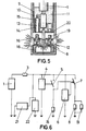
- Figures 2 to 5.- Show a schematic representation in a sectional side view of an electro-mechanical fuse for a hand grenade constructed according to the object of the invention, showing only its lower part where the improvements are found corresponding to arrangement of the elements of the explosive chain. Specifically, Figure 2 shows the fuse in a resting state (storage, transport, handling and up to the moment of launching). Figure 3 shows the fuse in a launching safety state (after launching). Figure 4 shows the fuse in an armed state (final moments before launching). Figure 5 shows the fuse at the time of initiation (explosion of the detonator and successively of the multiplier and the main explosive charge).
- Figure 6.- Shows a schematic block diagram of the modified electronic circuit, including the modified arrangement of the elements of the explosive chain.
-
- Description of the improvements with reference to the figures will first be made regarding the arrangement of the elements of the explosive chain, and later regarding the electronic circuitry with block diagrams shown in figures 1 and 6.
- As mentioned above, the improvements of the invention are applicable to electro-mechanical fuses comprising a container (6) which houses a slider (10) within which is placed an electric generator (1), which slider (10) can move axially within container (9) when a lever (not shown) is moved, by means as those of Spanish invention patent no. 9502554, while generator (1) is activated by a spring coil and a transmission mechanism (also not shown, as they are identical to those of said patent 95502554). Generator (1) produces the electrical power required for operation of the entire fuse, and delivers it to an electronic circuit (11) which at due time discharges it on detonator (8), causing a detonation which through multiplier (12) will be transmitted to the main explosive charge of the grenade (not shown).
- From this basic structure, the improvements of the invention are centred in that on the side of the electronics module (11) is placed an expansion chamber (13), consisting of a bushing (14) of a suitable strength on whose top end, closing it, is an electro-explosive actuator (15), while on its bottom end is inserted a piston (16) integrally connected to support (17) of multiplier (12), so that said multiplier (12) instead of being attached to container (9) as in invention patent 9502554, is carried by the slider (10) during the mechanical operation of the fuse, as shown in figure 2.
- In a resting position, as shown in said figure 2, the detonator (8) and the multiplier (12) are unaligned by the interposition of wall (18). This situation remains throughout the launching safety time, as shown in figure 3.
- A trip switch (19) placed at the bottom of slider (10) keeps detonator (8) short-circuited.
- Electronics module (11), as shown in figure 6, comprises two timers (4) and (6), the first (4) analogue and with a shorter time set, preferably 3.5 seconds, which discharges through switch (5) on electro-explosive actuator (15), which acts on piston (16) causing the motion of the multiplier support (17) and the multiplier itself (12) to the aligned situation shown in figure 4, finalising the arming process of the fuse.
- This axial movement of multiplier (12), and more specifically of its support (17), activates the trip switch (19), opening the short-circuit of detonator (8), which is now in an aligned position with multiplier (12) and can be initiated.
- At the end of the second timer (6), digital and with a somewhat longer time set, preferably four seconds, it discharges through switch (7) on detonator (8), which generates a detonation wave which through multiplier (12) and amplified by it is transmitted to the main explosive charge of the grenade.
- Electrical power supply is obtained from electrical generator (1) driven by a mechanism similar to that described in patent 9502554. The power generated arrives at the electronic circuit and is stored by two redundant capacitors (21) and (22). A diode (3) prevents the energy from dissipating if there is a short-circuit external to the electronic circuit itself.
- At the time of receiving power from capacitors (21) and (22), the aforementioned timers (4) and (6) are started. The first (4) is an analogue timer of the first degree which controls switch (5), jointly forming what is known as the "launching safety ". The second (6) is a precision digital timer which acts on switch (7), determining the "operation time".
- At the end of the launching safety time switch (5) is closed, so that after the operation time runs out and switch (7) is closed the electrical energy stored in capacitors (21) and (22) is discharged on detonator (8), initiating the explosion of the hand grenade.
- As the two timers operate under different technology, analogue and digital, they are independent from each other to external stimuli which could never be a cause of joint failure. Thus, even if an external circumstance were to cause malfunction of one of the two timers the other would still operate correctly, ensuring that the hand grenade will never explode before the end of the launching safety period.
- To complete the independence from external agents capacitors (21) and (22), and any other electronic components which, due to design or safety requirements, are redundant will be placed in different positions and orientations, thereby preventing a single external stimulus causing the failure of both redundant components.
Claims (6)
- Improvements in electro-mechanical fuses for hand grenades, applicable to the types of fuse which comprise a container (9) which houses a slider (10) which can move axially and in which in turn is housed an electrical generator (1), which produces power required by the entire fuse, delivering it to an electronic circuit (11) which with a timed delay discharges it on a detonator (8) which detonation, through a multiplier (12) is transmitted to the main explosive charge of the grenade, essentially characterised in that it includes at least two mutually independent electronic timers which can be configured, combined and/or preset independently from each other, acting sequentially for the final explosion of the grenade to occur.
- Improvements in electro-mechanical fuses for hand grenades, as claimed in claim 1, characterised in that the electronic timing is provided by corresponding timers (4) and (6) which operate by different technological principles, digital or analogue, so that if they are redundant components they are placed in different positions and/or orientations.
- Improvements in electro-mechanical fuses for hand grenades, as claimed in claim 1, characterised in that the independent electronic timing is provided by corresponding electronic timers (4) and (6) which operate by the same technologic principle, analogue or digital, with identical or similar components, which are part of each delay, so that in this case the redundant components are placed in different positions and/or orientations.
- Improvements in electro-mechanical fuses for hand grenades, as claimed in above claims, characterised in that detonator (8) and corresponding multiplier (12) as elements of the explosive chain, are kept unaligned during their assembly, storage, transport, handling, launching and flight, until a preset launching safety time runs out, at which time said components, detonator (8) and multiplier (12) are aligned.
- Improvements in electro-mechanical fuses for hand grenades, as claimed in above claims, characterised in that inside movable slider (10) and laterally with respect to detonator (8) is provided an expansion chamber (13) embodied in a bushing (14) , at the top end of which is placed an electro-explosive actuator (15), while on its bottom end it houses a piston (16) integrally attached to support (17) of multiplier (12), so that when slider (10) moves, multiplier support (17) moves along with it, maintaining the unaligned arrangement of multiplier (12) and detonator (8), while a trip switch (19) keeps detonator (8) short-circuited, preventing its initiation.
- Improvements in electro-mechanical fuses for hand grenades, as claimed in above claims, characterised in that electronic timer (4) runs a somewhat shorter time than electronic timer (6), the former acting through a switch (5) on the electro-explosive actuator (15), the activation of which causes the axial displacement of piston (16) attached to support (17) in multiplier (12), carrying the latter to an aligned position with respect to detonator (8), while trip switch (19) causes the opening of the short-circuit of detonator (8), and after the time set by timer (6) runs out the latter discharges through the switch the electrical energy meant for initiation of detonator (8), which in its aligned position with multiplier (12) causes the explosion of the main explosive charge.
Applications Claiming Priority (3)
| Application Number | Priority Date | Filing Date | Title |
|---|---|---|---|
| ES9902367 | 1999-10-27 | ||
| ES009902367A ES2176060B1 (en) | 1999-10-27 | 1999-10-27 | IMPROVEMENTS IN MECHAN-ELECTRONIC SPOOLS FOR HAND GRENADES. |
| PCT/ES2000/000214 WO2001031283A1 (en) | 1999-10-27 | 2000-06-14 | Improvements to mecanotronic fuses for hand grenades |
Publications (2)
| Publication Number | Publication Date |
|---|---|
| EP1225418A1 true EP1225418A1 (en) | 2002-07-24 |
| EP1225418B1 EP1225418B1 (en) | 2004-02-11 |
Family
ID=8310394
Family Applications (1)
| Application Number | Title | Priority Date | Filing Date |
|---|---|---|---|
| EP00942152A Expired - Lifetime EP1225418B1 (en) | 1999-10-27 | 2000-06-14 | Improvements to mecanotronic fuses for hand grenades |
Country Status (10)
| Country | Link |
|---|---|
| US (2) | US7013809B1 (en) |
| EP (1) | EP1225418B1 (en) |
| AT (1) | ATE259498T1 (en) |
| AU (1) | AU5687000A (en) |
| CA (1) | CA2386691C (en) |
| DE (1) | DE60008272T2 (en) |
| ES (1) | ES2176060B1 (en) |
| IL (1) | IL149381A0 (en) |
| WO (1) | WO2001031283A1 (en) |
| ZA (1) | ZA200202636B (en) |
Cited By (11)
| Publication number | Priority date | Publication date | Assignee | Title |
|---|---|---|---|---|
| EP1271091A1 (en) * | 2001-06-29 | 2003-01-02 | Tda Armements S.A.S. | Pyrotechnic activation safety-system |
| RU2255302C1 (en) * | 2004-02-17 | 2005-06-27 | Федеральное государственное унитарное предприятие "Научно-исследовательский институт "Поиск" | Safety-and-actuating mechanism of fuse |
| EP1909059A1 (en) | 2006-10-02 | 2008-04-09 | JUNGHANS Microtec GmbH | Projectile detonator |
| RU2333458C1 (en) * | 2006-11-14 | 2008-09-10 | Федеральное государственное унитарное предприятие "Научно-исследовательский технологический институт им. П.И. Снегирева" | Safety and arming unit of guided munitions |
| RU2413176C1 (en) * | 2009-10-06 | 2011-02-27 | Федеральное государственное унитарное предприятие "Российский Федеральный ядерный центр - Всероссийский научно-исследовательский институт экспериментальной физики" - ФГУП "РФЯЦ - ВНИИЭФ" | Safety-and-arming fuse mechanism |
| RU2625660C2 (en) * | 2015-12-07 | 2017-07-18 | Федеральное государственное казенное военное образовательное учреждение высшего профессионального образования "Военная академия Ракетных войск стратегического назначения имени Петра Великого" Министерства обороны Российской Федерации | Safety-launching device of the on-board earth-based automation detonation circuit |
| RU2633838C1 (en) * | 2016-10-10 | 2017-10-18 | Владимир Викторович Черниченко | Safety actuator |
| RU2642583C1 (en) * | 2016-10-10 | 2018-01-25 | Виталий Борисович Шепеленко | Safety-actuating mechanism |
| RU2671017C1 (en) * | 2017-09-08 | 2018-10-29 | Российская Федерация, от имени которой выступает Министерство обороны Российской Федерации | Safety and arming unit |
| RU2745639C1 (en) * | 2020-02-17 | 2021-03-29 | Российская Федерация, от имени которой выступает Государственная корпорация по атомной энергии "Росатом" (Госкорпорация "Росатом") | PYRO DRIVE LOCKING MECHANISM |
| RU2767809C1 (en) * | 2021-07-30 | 2022-03-22 | Российская Федерация, от имени которой выступает Государственная корпорация по атомной энергии "Росатом" (Госкорпорация "Росатом") | Safety and arming device of fuse |
Families Citing this family (10)
| Publication number | Priority date | Publication date | Assignee | Title |
|---|---|---|---|---|
| DE10316875B4 (en) * | 2003-04-11 | 2005-07-21 | Diehl Bgt Defence Gmbh & Co. Kg | Mechano-electric detonator for a hand grenade |
| US9234730B1 (en) * | 2007-10-22 | 2016-01-12 | Kendrick Cook | Hand grenade |
| RU2489678C2 (en) * | 2011-10-28 | 2013-08-10 | Федеральное государственное унитарное предприятие "Научно-исследовательский институт "Поиск" | Electronic remote detonating fuse of missile projectile |
| US8887640B1 (en) | 2012-09-10 | 2014-11-18 | The United States Of America As Represented By The Secretary Of The Army | Electro-mechanical fuze for hand grenades |
| CN103411486A (en) * | 2013-08-21 | 2013-11-27 | 南通迅翔自动化设备有限公司 | AC/DC (alternative current/direct current) withstand voltage protective device of digital electronic detonator |
| HUE042097T2 (en) | 2014-12-10 | 2019-06-28 | Ruag Ammotec Ag | Fuze system for hand grenades |
| US10088288B1 (en) | 2016-10-06 | 2018-10-02 | The United States Of America As Represented By The Secretary Of The Army | Munition fuze with blast initiated inductance generator for power supply and laser ignitor |
| CO2017012014A1 (en) * | 2017-11-27 | 2017-12-15 | Ind Militar Indumil | Electromechanical fuse for aerial bomb with selection of delay in arming and pre-launch safety devices |
| CN109506527B (en) * | 2018-11-20 | 2022-03-15 | 南京理工大学 | Electromechanical time fuse for antiaircraft gun hail suppression and rain enhancement bomb |
| CN114241883B (en) * | 2021-12-27 | 2023-10-17 | 中国人民解放军陆军工程大学 | Explosion power teaching presentation device |
Family Cites Families (18)
| Publication number | Priority date | Publication date | Assignee | Title |
|---|---|---|---|---|
| US3504632A (en) * | 1968-06-04 | 1970-04-07 | Us Navy | Time delay fuze |
| US4145971A (en) * | 1977-10-19 | 1979-03-27 | Motorola, Inc. | Electronic time delay safety and arming mechanism |
| FR2483068B1 (en) * | 1980-05-21 | 1986-09-26 | Ruggieri Ets | ELECTRONIC ROCKET FOR HAND OR RIFLE GRENADE |
| FR2528967B1 (en) * | 1982-06-21 | 1986-11-28 | France Etat | ELECTRONIC IGNITION PLUG WITH USER PROGRAMMABLE DELAY |
| CA1233896A (en) * | 1983-04-11 | 1988-03-08 | Kenneth N. Jarrott | Programmable electronic delay fuse |
| FR2559895B1 (en) * | 1984-02-20 | 1988-09-09 | Serat | HAND GRENADE |
| GB8622806D0 (en) * | 1986-09-23 | 1987-02-04 | Royal Ordnance Plc | Detonation fuzes |
| GB2227384B (en) * | 1988-11-18 | 1992-05-27 | Graviner Ltd Kidde | Electrical timing arrangements and methods |
| US5131328A (en) * | 1991-12-13 | 1992-07-21 | The United States Of America As Represented By The Secretary Of The Navy | Safety and arming system for tube launched projectile |
| US5271327A (en) * | 1992-06-19 | 1993-12-21 | Alliant Techsystems Inc. | Elecro-mechanical base element fuze |
| US5621184A (en) * | 1995-04-10 | 1997-04-15 | The Ensign-Bickford Company | Programmable electronic timer circuit |
| US5693906A (en) * | 1995-09-28 | 1997-12-02 | Alliant Techsystems Inc. | Electro-mechanical safety and arming device |
| ES2136485B1 (en) | 1995-12-29 | 2000-05-16 | Instalaza Sa | MECHANICAL-ELECTRONIC SPLET FOR HAND GRENADE. |
| FR2745080B1 (en) * | 1996-02-21 | 1998-05-15 | Ruggieri | DELAYED IGNITION PLUG FOR PYROTECHNIC APPARATUS |
| US6082267A (en) * | 1997-10-03 | 2000-07-04 | Bulova Technologies, L.L.C. | Electronic, out-of-line safety fuze for munitions such as hand grenades |
| US6142080A (en) * | 1998-01-14 | 2000-11-07 | General Dynamics Armament Systems, Inc. | Spin-decay self-destruct fuze |
| US6272995B1 (en) * | 1999-09-14 | 2001-08-14 | Kdi Precision Products, Inc. | High precision fuze for a munition |
| US6629498B1 (en) * | 2002-05-10 | 2003-10-07 | The United States Of America As Represented By The Secretary Of The Navy | Proximity submunition fuze safety logic |
-
1999
- 1999-10-27 ES ES009902367A patent/ES2176060B1/en not_active Expired - Fee Related
-
2000
- 2000-06-14 AT AT00942152T patent/ATE259498T1/en not_active IP Right Cessation
- 2000-06-14 IL IL14938100A patent/IL149381A0/en unknown
- 2000-06-14 EP EP00942152A patent/EP1225418B1/en not_active Expired - Lifetime
- 2000-06-14 DE DE60008272T patent/DE60008272T2/en not_active Expired - Lifetime
- 2000-06-14 CA CA002386691A patent/CA2386691C/en not_active Expired - Fee Related
- 2000-06-14 AU AU56870/00A patent/AU5687000A/en not_active Abandoned
- 2000-06-14 US US10/111,443 patent/US7013809B1/en not_active Expired - Fee Related
- 2000-06-14 WO PCT/ES2000/000214 patent/WO2001031283A1/en not_active Ceased
-
2002
- 2002-04-04 ZA ZA200202636A patent/ZA200202636B/en unknown
-
2006
- 2006-01-31 US US11/343,636 patent/US20060266248A1/en not_active Abandoned
Non-Patent Citations (1)
| Title |
|---|
| See references of WO0131283A1 * |
Cited By (13)
| Publication number | Priority date | Publication date | Assignee | Title |
|---|---|---|---|---|
| EP1271091A1 (en) * | 2001-06-29 | 2003-01-02 | Tda Armements S.A.S. | Pyrotechnic activation safety-system |
| RU2255302C1 (en) * | 2004-02-17 | 2005-06-27 | Федеральное государственное унитарное предприятие "Научно-исследовательский институт "Поиск" | Safety-and-actuating mechanism of fuse |
| EP1909059A1 (en) | 2006-10-02 | 2008-04-09 | JUNGHANS Microtec GmbH | Projectile detonator |
| US7614346B2 (en) | 2006-10-02 | 2009-11-10 | Junghans Microtech Gmbh | Projectile fuze with fuze electronics including a timer/counter |
| RU2333458C1 (en) * | 2006-11-14 | 2008-09-10 | Федеральное государственное унитарное предприятие "Научно-исследовательский технологический институт им. П.И. Снегирева" | Safety and arming unit of guided munitions |
| RU2333458C9 (en) * | 2006-11-14 | 2008-11-10 | Федеральное государственное унитарное предприятие "Научно-исследовательский технологический институт им. П.И. Снегирева" | Safety and arming unit of guided munitions |
| RU2413176C1 (en) * | 2009-10-06 | 2011-02-27 | Федеральное государственное унитарное предприятие "Российский Федеральный ядерный центр - Всероссийский научно-исследовательский институт экспериментальной физики" - ФГУП "РФЯЦ - ВНИИЭФ" | Safety-and-arming fuse mechanism |
| RU2625660C2 (en) * | 2015-12-07 | 2017-07-18 | Федеральное государственное казенное военное образовательное учреждение высшего профессионального образования "Военная академия Ракетных войск стратегического назначения имени Петра Великого" Министерства обороны Российской Федерации | Safety-launching device of the on-board earth-based automation detonation circuit |
| RU2633838C1 (en) * | 2016-10-10 | 2017-10-18 | Владимир Викторович Черниченко | Safety actuator |
| RU2642583C1 (en) * | 2016-10-10 | 2018-01-25 | Виталий Борисович Шепеленко | Safety-actuating mechanism |
| RU2671017C1 (en) * | 2017-09-08 | 2018-10-29 | Российская Федерация, от имени которой выступает Министерство обороны Российской Федерации | Safety and arming unit |
| RU2745639C1 (en) * | 2020-02-17 | 2021-03-29 | Российская Федерация, от имени которой выступает Государственная корпорация по атомной энергии "Росатом" (Госкорпорация "Росатом") | PYRO DRIVE LOCKING MECHANISM |
| RU2767809C1 (en) * | 2021-07-30 | 2022-03-22 | Российская Федерация, от имени которой выступает Государственная корпорация по атомной энергии "Росатом" (Госкорпорация "Росатом") | Safety and arming device of fuse |
Also Published As
| Publication number | Publication date |
|---|---|
| AU5687000A (en) | 2001-05-08 |
| US20060266248A1 (en) | 2006-11-30 |
| ATE259498T1 (en) | 2004-02-15 |
| US7013809B1 (en) | 2006-03-21 |
| ES2176060B1 (en) | 2004-02-01 |
| WO2001031283A1 (en) | 2001-05-03 |
| ES2176060A1 (en) | 2002-11-16 |
| IL149381A0 (en) | 2002-11-10 |
| EP1225418B1 (en) | 2004-02-11 |
| CA2386691C (en) | 2008-04-29 |
| DE60008272D1 (en) | 2004-03-18 |
| CA2386691A1 (en) | 2001-05-03 |
| DE60008272T2 (en) | 2004-12-16 |
| ZA200202636B (en) | 2003-06-25 |
Similar Documents
| Publication | Publication Date | Title |
|---|---|---|
| EP1225418B1 (en) | Improvements to mecanotronic fuses for hand grenades | |
| US6622629B2 (en) | Submunition fuzing and self-destruct using MEMS arm fire and safe and arm devices | |
| US8887640B1 (en) | Electro-mechanical fuze for hand grenades | |
| US5485788A (en) | Combination explosive primer and electro-explosive device | |
| US5585592A (en) | Shock tolerant fuze | |
| US5536990A (en) | Piezoelectric igniter | |
| US4603635A (en) | Dual safing for base element fuze | |
| US6244184B1 (en) | Fuze for submunition grenade | |
| CN115823971A (en) | Patrol missile electromechanical triggering fuse | |
| US20040231547A1 (en) | Fuze explosive ordance disposal circuit | |
| US6082267A (en) | Electronic, out-of-line safety fuze for munitions such as hand grenades | |
| US5147975A (en) | Remotely settable, multi-output, electronic time fuze and method of operation | |
| US3359904A (en) | Piezoelectric projectile fuze | |
| CN109307457A (en) | A microelectromechanical sequential logic ignition control device | |
| US4727809A (en) | Detonation safety mechanism | |
| RU2540987C1 (en) | Fuse for missile projectiles and method of its application | |
| US20220390217A1 (en) | Electronic self-destructing fuse structure | |
| US7478595B1 (en) | Base mounted airburst fuze for projectile | |
| US6145439A (en) | RC time delay self-destruct fuze | |
| US10088288B1 (en) | Munition fuze with blast initiated inductance generator for power supply and laser ignitor | |
| US3641938A (en) | Percussion or vibration fuse for explosive charge | |
| EP3690322B1 (en) | Electromechanical contact fuse for multi-purpose aircraft ammunition | |
| US4047484A (en) | Fuze with bimetallic spring delay module | |
| EP0605356B1 (en) | Self-destructive electronic fuse | |
| EP0781975B1 (en) | Mechano-electronic fuze for hand grenade |
Legal Events
| Date | Code | Title | Description |
|---|---|---|---|
| PUAI | Public reference made under article 153(3) epc to a published international application that has entered the european phase |
Free format text: ORIGINAL CODE: 0009012 |
|
| 17P | Request for examination filed |
Effective date: 20020408 |
|
| AK | Designated contracting states |
Kind code of ref document: A1 Designated state(s): AT BE CH CY DE DK ES FI FR GB GR IE IT LI LU MC NL PT SE |
|
| AX | Request for extension of the european patent |
Free format text: AL;LT;LV;MK;RO;SI |
|
| 17Q | First examination report despatched |
Effective date: 20021115 |
|
| GRAP | Despatch of communication of intention to grant a patent |
Free format text: ORIGINAL CODE: EPIDOSNIGR1 |
|
| GRAS | Grant fee paid |
Free format text: ORIGINAL CODE: EPIDOSNIGR3 |
|
| GRAA | (expected) grant |
Free format text: ORIGINAL CODE: 0009210 |
|
| AK | Designated contracting states |
Kind code of ref document: B1 Designated state(s): AT BE CH CY DE DK ES FI FR GB GR IE IT LI LU MC NL PT SE |
|
| PG25 | Lapsed in a contracting state [announced via postgrant information from national office to epo] |
Ref country code: FI Free format text: LAPSE BECAUSE OF FAILURE TO SUBMIT A TRANSLATION OF THE DESCRIPTION OR TO PAY THE FEE WITHIN THE PRESCRIBED TIME-LIMIT Effective date: 20040211 Ref country code: BE Free format text: LAPSE BECAUSE OF FAILURE TO SUBMIT A TRANSLATION OF THE DESCRIPTION OR TO PAY THE FEE WITHIN THE PRESCRIBED TIME-LIMIT Effective date: 20040211 Ref country code: AT Free format text: LAPSE BECAUSE OF FAILURE TO SUBMIT A TRANSLATION OF THE DESCRIPTION OR TO PAY THE FEE WITHIN THE PRESCRIBED TIME-LIMIT Effective date: 20040211 Ref country code: CY Free format text: LAPSE BECAUSE OF FAILURE TO SUBMIT A TRANSLATION OF THE DESCRIPTION OR TO PAY THE FEE WITHIN THE PRESCRIBED TIME-LIMIT Effective date: 20040211 Ref country code: ES Free format text: LAPSE BECAUSE OF FAILURE TO SUBMIT A TRANSLATION OF THE DESCRIPTION OR TO PAY THE FEE WITHIN THE PRESCRIBED TIME-LIMIT Effective date: 20040211 Ref country code: NL Free format text: LAPSE BECAUSE OF FAILURE TO SUBMIT A TRANSLATION OF THE DESCRIPTION OR TO PAY THE FEE WITHIN THE PRESCRIBED TIME-LIMIT Effective date: 20040211 |
|
| REG | Reference to a national code |
Ref country code: GB Ref legal event code: FG4D |
|
| REG | Reference to a national code |
Ref country code: CH Ref legal event code: EP |
|
| REG | Reference to a national code |
Ref country code: IE Ref legal event code: FG4D |
|
| REG | Reference to a national code |
Ref country code: CH Ref legal event code: NV Representative=s name: ISLER & PEDRAZZINI AG |
|
| REF | Corresponds to: |
Ref document number: 60008272 Country of ref document: DE Date of ref document: 20040318 Kind code of ref document: P |
|
| PG25 | Lapsed in a contracting state [announced via postgrant information from national office to epo] |
Ref country code: GR Free format text: LAPSE BECAUSE OF FAILURE TO SUBMIT A TRANSLATION OF THE DESCRIPTION OR TO PAY THE FEE WITHIN THE PRESCRIBED TIME-LIMIT Effective date: 20040511 Ref country code: SE Free format text: LAPSE BECAUSE OF FAILURE TO SUBMIT A TRANSLATION OF THE DESCRIPTION OR TO PAY THE FEE WITHIN THE PRESCRIBED TIME-LIMIT Effective date: 20040511 Ref country code: DK Free format text: LAPSE BECAUSE OF FAILURE TO SUBMIT A TRANSLATION OF THE DESCRIPTION OR TO PAY THE FEE WITHIN THE PRESCRIBED TIME-LIMIT Effective date: 20040511 |
|
| PG25 | Lapsed in a contracting state [announced via postgrant information from national office to epo] |
Ref country code: IE Free format text: LAPSE BECAUSE OF NON-PAYMENT OF DUE FEES Effective date: 20040614 Ref country code: LU Free format text: LAPSE BECAUSE OF NON-PAYMENT OF DUE FEES Effective date: 20040614 |
|
| PG25 | Lapsed in a contracting state [announced via postgrant information from national office to epo] |
Ref country code: MC Free format text: LAPSE BECAUSE OF NON-PAYMENT OF DUE FEES Effective date: 20040630 |
|
| LTIE | Lt: invalidation of european patent or patent extension |
Effective date: 20040211 |
|
| NLV1 | Nl: lapsed or annulled due to failure to fulfill the requirements of art. 29p and 29m of the patents act | ||
| ET | Fr: translation filed | ||
| PLBE | No opposition filed within time limit |
Free format text: ORIGINAL CODE: 0009261 |
|
| STAA | Information on the status of an ep patent application or granted ep patent |
Free format text: STATUS: NO OPPOSITION FILED WITHIN TIME LIMIT |
|
| 26N | No opposition filed |
Effective date: 20041112 |
|
| REG | Reference to a national code |
Ref country code: IE Ref legal event code: MM4A |
|
| REG | Reference to a national code |
Ref country code: CH Ref legal event code: PCAR Free format text: ISLER & PEDRAZZINI AG;POSTFACH 1772;8027 ZUERICH (CH) |
|
| PG25 | Lapsed in a contracting state [announced via postgrant information from national office to epo] |
Ref country code: PT Free format text: LAPSE BECAUSE OF NON-PAYMENT OF DUE FEES Effective date: 20040711 |
|
| PGFP | Annual fee paid to national office [announced via postgrant information from national office to epo] |
Ref country code: CH Payment date: 20110629 Year of fee payment: 12 |
|
| PGFP | Annual fee paid to national office [announced via postgrant information from national office to epo] |
Ref country code: GB Payment date: 20110607 Year of fee payment: 12 |
|
| PGFP | Annual fee paid to national office [announced via postgrant information from national office to epo] |
Ref country code: FR Payment date: 20110720 Year of fee payment: 12 |
|
| PGFP | Annual fee paid to national office [announced via postgrant information from national office to epo] |
Ref country code: DE Payment date: 20110624 Year of fee payment: 12 |
|
| PGFP | Annual fee paid to national office [announced via postgrant information from national office to epo] |
Ref country code: IT Payment date: 20110628 Year of fee payment: 12 |
|
| REG | Reference to a national code |
Ref country code: CH Ref legal event code: PL |
|
| REG | Reference to a national code |
Ref country code: CH Ref legal event code: PL |
|
| GBPC | Gb: european patent ceased through non-payment of renewal fee |
Effective date: 20120614 |
|
| PG25 | Lapsed in a contracting state [announced via postgrant information from national office to epo] |
Ref country code: IT Free format text: LAPSE BECAUSE OF NON-PAYMENT OF DUE FEES Effective date: 20120614 |
|
| REG | Reference to a national code |
Ref country code: FR Ref legal event code: ST Effective date: 20130228 |
|
| REG | Reference to a national code |
Ref country code: DE Ref legal event code: R119 Ref document number: 60008272 Country of ref document: DE Effective date: 20130101 |
|
| PG25 | Lapsed in a contracting state [announced via postgrant information from national office to epo] |
Ref country code: LI Free format text: LAPSE BECAUSE OF NON-PAYMENT OF DUE FEES Effective date: 20120630 Ref country code: GB Free format text: LAPSE BECAUSE OF NON-PAYMENT OF DUE FEES Effective date: 20120614 Ref country code: FR Free format text: LAPSE BECAUSE OF NON-PAYMENT OF DUE FEES Effective date: 20120702 Ref country code: CH Free format text: LAPSE BECAUSE OF NON-PAYMENT OF DUE FEES Effective date: 20120630 Ref country code: DE Free format text: LAPSE BECAUSE OF NON-PAYMENT OF DUE FEES Effective date: 20130101 |