EP1227276A2 - Doppelwandige Anschlussleitung - Google Patents
Doppelwandige Anschlussleitung Download PDFInfo
- Publication number
- EP1227276A2 EP1227276A2 EP01126987A EP01126987A EP1227276A2 EP 1227276 A2 EP1227276 A2 EP 1227276A2 EP 01126987 A EP01126987 A EP 01126987A EP 01126987 A EP01126987 A EP 01126987A EP 1227276 A2 EP1227276 A2 EP 1227276A2
- Authority
- EP
- European Patent Office
- Prior art keywords
- bellows
- double
- walled
- tubes
- rings
- Prior art date
- Legal status (The legal status is an assumption and is not a legal conclusion. Google has not performed a legal analysis and makes no representation as to the accuracy of the status listed.)
- Granted
Links
Images


Classifications
-
- F—MECHANICAL ENGINEERING; LIGHTING; HEATING; WEAPONS; BLASTING
- F23—COMBUSTION APPARATUS; COMBUSTION PROCESSES
- F23J—REMOVAL OR TREATMENT OF COMBUSTION PRODUCTS OR COMBUSTION RESIDUES; FLUES
- F23J13/00—Fittings for chimneys or flues
- F23J13/02—Linings; Jackets; Casings
- F23J13/025—Linings; Jackets; Casings composed of concentric elements, e.g. double walled
-
- F—MECHANICAL ENGINEERING; LIGHTING; HEATING; WEAPONS; BLASTING
- F23—COMBUSTION APPARATUS; COMBUSTION PROCESSES
- F23J—REMOVAL OR TREATMENT OF COMBUSTION PRODUCTS OR COMBUSTION RESIDUES; FLUES
- F23J13/00—Fittings for chimneys or flues
- F23J13/04—Joints; Connections
-
- F—MECHANICAL ENGINEERING; LIGHTING; HEATING; WEAPONS; BLASTING
- F23—COMBUSTION APPARATUS; COMBUSTION PROCESSES
- F23J—REMOVAL OR TREATMENT OF COMBUSTION PRODUCTS OR COMBUSTION RESIDUES; FLUES
- F23J2211/00—Flue gas duct systems
- F23J2211/10—Balanced flues (combining air supply and flue gas exhaust)
- F23J2211/101—Balanced flues (combining air supply and flue gas exhaust) with coaxial duct arrangement
-
- F—MECHANICAL ENGINEERING; LIGHTING; HEATING; WEAPONS; BLASTING
- F23—COMBUSTION APPARATUS; COMBUSTION PROCESSES
- F23J—REMOVAL OR TREATMENT OF COMBUSTION PRODUCTS OR COMBUSTION RESIDUES; FLUES
- F23J2213/00—Chimneys or flues
- F23J2213/20—Joints; Connections
- F23J2213/203—Joints; Connections between stack/duct and combustion apparatus
Definitions
- the invention relates to a double-walled connecting line for connecting a burner to one in a building installed double-walled exhaust pipe.
- Burners especially boilers, are increasing Dimensions connected to double-walled connecting cables, at which an internal wiring harness an exhaust pipe forms and between the inner wiring harness and the outer duct wall lying jacket space for supply from fresh air to the burner.
- Bellows tubes made of flexibly connected conical bellows rings are known (WO 99/56049). It is known (DE 198 02 417 C1), which laid in the fireplace double-walled connecting cable on bellows tubes perform, with the burners connected via pipes become.
- the object of the invention is therefore a double-walled Connection line of the type mentioned at the beginning create that in a constructively simple manner and with low workload, especially on the construction site, even under difficult spatial conditions Connection of the burner to the one installed in the building double-walled exhaust pipe enables.
- connection line two essentially concentric has mutually extending flexible bellows tubes, between which radial spacers are arranged, and that the bellows tubes have bistable sections.
- the flexible design of the double-walled connecting cable with bistable sections allows in very simple Way an adjustment of the line course to the respective local conditions on the construction site. For example can change the connection line starting from the burner Beams or other internals are led around without that for this each double-walled elbows or similar elements would be required.
- the adaptation happens in a very simple way because the double-walled connecting cable is bent and laid in such a way as the spatial conditions allow. at the same time can also be a fluidically favorable course can be selected with deflections with a small radius be avoided.
- the flexible between the two Bellows tubes or hoses arranged radial Spacers ensure that even with one more curved course compliance with a sufficient Distance between the inner bellows tube and the outer bellows tube is ensured so that unhindered jacket space for the fresh air supply preserved.
- each bellows tube each in essentially from flexibly connected conical Bellows rings exist.
- Each bellows ring preferably forms one bistable elastic element. Every conical bellows ring has two stable positions, so that adjacent bellows rings either at an approximately predetermined angle to each other are arranged, several bellows rings a bellows form, or lie flat against each other and a block of Form bellows rings.
- the effective length of the bellows tubes results from what proportion of their bellows rings in this Form a bellows or a block. By Applying tensile or compressive forces in In the longitudinal direction, this effective length of the bellows tubes to be changed.
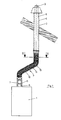
- Fig. 1 is an example of a burner 1 Boiler indicated, for example in the attic a building is arranged.
- the combustion device 1 is connected to a double-walled exhaust pipe 2 connected, one Roof duct forms and consists of two rigid, concentric tubes 3 and 4 arranged to each other.
- the inner Tube 3 forms an exhaust pipe; the outer tube 4 is in All-round distance to the inner tube 3 arranged so that A jacket space 5 is created, the fresh air supply to Burner 1 is used.
- Pipe socket 6 there is an internal one on the combustion device 1 Pipe socket 6 provided through which the exhaust gases exit.
- An outer pipe socket 7 encloses the inner one Pipe socket 6 concentric; in between is a jacket space 8 formed by which the fresh air to the burner 1, in particular a condensing boiler.
- the pipe socket 6 and 7 of the burner 1 are one flexible, double-walled connecting line 9 with the double-walled exhaust pipe 2 connected.
- the Connection line 9 has two essentially concentric flexible bellows pipes running towards each other, namely an inner bellows tube 10 and an outer Bellows tube 11, between which radial spacers 12 (Fig. 2) are arranged around the two bellows tubes or hoses 10 and 11 in a concentric arrangement. and essentially constant radial distance to hold to each other.
- each of the two Bellows tubes 10, 11 a flexible bellows section 14, which is essentially flexible with each other connected conical bellows rings 15 is made of plastic.
- Each bellows ring 15 forms a bistable elastic Element. Adjacent bellows rings 15 can therefore either in an essentially predetermined angle to each other be arranged, as in FIG. 3 in an area 16 is shown, the bellows rings 15 an elastic Form bellows, or the bellows rings can lie essentially flat on top of each other and in one Section 17 an axially substantially rigid block form.
- the effective length of the bellows tube 10 or 11 can be done in a very simple way during assembly be determined that a tensile force in the axial direction or pressure force exerted on the bellows compensator 11 will, so a more or less large part of its Bellows rings 15 from the bellows arrangement as in area 16 in the block arrangement as in area 17 and vice versa transforms.
- the bellows tube 10 or 11 is in each of the Chosen lengths essentially stable, but leaves one axial length change due to elastic deformations.
Landscapes
- Engineering & Computer Science (AREA)
- Mechanical Engineering (AREA)
- General Engineering & Computer Science (AREA)
- Rigid Pipes And Flexible Pipes (AREA)
- Joints Allowing Movement (AREA)
- Multi-Conductor Connections (AREA)
- Exhaust Silencers (AREA)
Abstract
Description
Claims (3)
- Doppelwandige Anschlussleitung zur Verbindung eines Brenngeräts mit einer in einem Gebäude verlegten doppelwandigen Abgasleitung, dadurch gekennzeichnet, dass die Anschlussleitung (9) zwei im wesentlichen konzentrisch zueinander verlaufende flexible Faltenbalgrohre (10, 11) aufweist, zwischen denen radiale Abstandshalter (12) angeordnet sind, und dass die Faltenbalgrohre (10, 11) bistabile Abschnitte aufweisen.
- Doppelwandige Anschlussleitung nach Anspruch 1, dadurch gekennzeichnet, dass die beiden Faltenbalgrohre (10, 11) jeweils aus flexibel miteinander verbundenen konischen Balgringen (15) bestehen.
- Doppelwandige Anschlussleitung nach Anspruch 2, dadurch gekennzeichnet, dass jeder Balgring (15) ein bistabiles elastisches Element bildet.
Applications Claiming Priority (2)
| Application Number | Priority Date | Filing Date | Title |
|---|---|---|---|
| DE10103383 | 2001-01-26 | ||
| DE10103383A DE10103383C5 (de) | 2001-01-26 | 2001-01-26 | Doppelwandige Anschlussleitung |
Publications (3)
| Publication Number | Publication Date |
|---|---|
| EP1227276A2 true EP1227276A2 (de) | 2002-07-31 |
| EP1227276A3 EP1227276A3 (de) | 2003-05-07 |
| EP1227276B1 EP1227276B1 (de) | 2006-09-13 |
Family
ID=7671751
Family Applications (1)
| Application Number | Title | Priority Date | Filing Date |
|---|---|---|---|
| EP01126987A Expired - Lifetime EP1227276B1 (de) | 2001-01-26 | 2001-11-14 | Doppelwandige Anschlussleitung |
Country Status (3)
| Country | Link |
|---|---|
| EP (1) | EP1227276B1 (de) |
| AT (1) | ATE339652T1 (de) |
| DE (2) | DE10103383C5 (de) |
Cited By (2)
| Publication number | Priority date | Publication date | Assignee | Title |
|---|---|---|---|---|
| WO2007006278A1 (de) * | 2005-07-08 | 2007-01-18 | Webasto Ag | Kraftfahrzeugheizung und abgasleitungsdurchführung |
| WO2020038921A1 (de) | 2018-08-21 | 2020-02-27 | Truma Gerätetechnik GmbH & Co. KG | Endseitige leitungsanordnung für ein heizgerät eines bewohnbaren fahrzeugs |
Citations (2)
| Publication number | Priority date | Publication date | Assignee | Title |
|---|---|---|---|---|
| DE19802417C1 (de) | 1998-01-23 | 1999-05-12 | Centrotherm Abgastechnik Gmbh | Bausatz für eine Luft-Abgas-Leitung |
| WO1999056049A1 (de) | 1998-04-29 | 1999-11-04 | Chemspeed Ltd. | Kunststoffrohr |
Family Cites Families (5)
| Publication number | Priority date | Publication date | Assignee | Title |
|---|---|---|---|---|
| GB1135270A (en) * | 1966-05-17 | 1968-12-04 | Matsushita Electric Industrial Co Ltd | Extensible and contractible flexible plastics hose |
| DE2042593A1 (de) * | 1970-08-27 | 1972-03-16 | Hefendehl, Hansfriedrich, 5893 Kierspe | Mantelkörper aus hartelastischem Kunststoff |
| US5393260A (en) * | 1993-12-10 | 1995-02-28 | Eljer Manufacturing, Inc. | Flexible double wall vent pipe |
| US5813701A (en) * | 1996-03-07 | 1998-09-29 | Gutter World, Inc. | Repositionable flexible downspout extension |
| GB9622497D0 (en) * | 1996-10-29 | 1997-01-08 | Rite Vent Limited | Flue duct |
-
2001
- 2001-01-26 DE DE10103383A patent/DE10103383C5/de not_active Expired - Fee Related
- 2001-11-14 AT AT01126987T patent/ATE339652T1/de not_active IP Right Cessation
- 2001-11-14 DE DE50111001T patent/DE50111001D1/de not_active Expired - Lifetime
- 2001-11-14 EP EP01126987A patent/EP1227276B1/de not_active Expired - Lifetime
Patent Citations (2)
| Publication number | Priority date | Publication date | Assignee | Title |
|---|---|---|---|---|
| DE19802417C1 (de) | 1998-01-23 | 1999-05-12 | Centrotherm Abgastechnik Gmbh | Bausatz für eine Luft-Abgas-Leitung |
| WO1999056049A1 (de) | 1998-04-29 | 1999-11-04 | Chemspeed Ltd. | Kunststoffrohr |
Cited By (5)
| Publication number | Priority date | Publication date | Assignee | Title |
|---|---|---|---|---|
| WO2007006278A1 (de) * | 2005-07-08 | 2007-01-18 | Webasto Ag | Kraftfahrzeugheizung und abgasleitungsdurchführung |
| WO2020038921A1 (de) | 2018-08-21 | 2020-02-27 | Truma Gerätetechnik GmbH & Co. KG | Endseitige leitungsanordnung für ein heizgerät eines bewohnbaren fahrzeugs |
| DE102018120396A1 (de) * | 2018-08-21 | 2020-02-27 | Truma Gerätetechnik GmbH & Co. KG | Endseitige Leitungsanordnung für ein Heizgerät eines bewohnbaren Fahrzeugs |
| CN112638673A (zh) * | 2018-08-21 | 2021-04-09 | 特鲁玛杰拉特技术有限公司 | 用于可居住交通工具的加热器的末端管道装置 |
| AU2019323649B2 (en) * | 2018-08-21 | 2021-09-30 | Truma Gerätetechnik GmbH & Co. KG | End line assembly for a heating device of a vehicle fit for habitation |
Also Published As
| Publication number | Publication date |
|---|---|
| ATE339652T1 (de) | 2006-10-15 |
| DE50111001D1 (de) | 2006-10-26 |
| DE10103383C5 (de) | 2005-07-21 |
| DE10103383C1 (de) | 2002-07-25 |
| EP1227276B1 (de) | 2006-09-13 |
| EP1227276A3 (de) | 2003-05-07 |
Similar Documents
| Publication | Publication Date | Title |
|---|---|---|
| DE10103385C2 (de) | Abgasanlage mit Mehrfachbelegung | |
| DE102009052674B4 (de) | Verfahren und Vorrichtung zum Verbinden von Doppelmantelrohren | |
| DE69401385T2 (de) | Schnellkupplung | |
| DE60115493T2 (de) | Rohrverbindungsvorrichtung | |
| DE3640043A1 (de) | Insbesondere zum fuehren eines z.b. gasfoermigen oder fluessigen stroemungsmediums dienendes rohr | |
| DE10103383C1 (de) | Doppelwandige Anschlussleitung | |
| DE19722967C1 (de) | Axial-Kompensator | |
| EP1227277B1 (de) | Abgasleitung für Brenngeräte in Gebäuden | |
| DE202005005056U1 (de) | Kunststoff-Rohr für Klima- und Lüftungs-Technik | |
| EP1199536A2 (de) | Wärmetauscher, insbesondere für Schwimmbäder | |
| DE3208516C2 (de) | ||
| DE9201997U1 (de) | Biegsames Rohr oder Rohrformstück | |
| EP1265020B1 (de) | Flexible Gasleitung | |
| DE202006006746U1 (de) | Verbindungseinheit mit Schelle | |
| DE3244722C1 (de) | Flexible Lutte | |
| DE4231760C2 (de) | Steckverbindung für Einsatzrohre aus Edelstahl, insbesondere für Rauch-, Abgas-, Be- und Entlüftungs- Systeme und Verwendung derselben | |
| DE1475874A1 (de) | Rohrkupplung | |
| AT505083B1 (de) | Halterung für rohre | |
| DE102006043801B4 (de) | Bauteil zum Kreuzen von mit einem Medium durchströmbaren Rohrleitungen | |
| DE202015100630U1 (de) | Schlauchschelle zum Sichern eines Wellschlauchs | |
| DE202017100820U1 (de) | Umlenkstück | |
| DE60129780T2 (de) | Rohrstruktur, Strömungskanalstruktur und Wärmetauscher | |
| DE20307821U1 (de) | Rohrleitung aus Elementen, mit schalldämpfendem Element | |
| DE19537479A1 (de) | Anschlußanordnung für ein Wellrohr | |
| DE4332007A1 (de) | Vorrichtung zum Ausgleichen von Rohrleitungslängen |
Legal Events
| Date | Code | Title | Description |
|---|---|---|---|
| PUAI | Public reference made under article 153(3) epc to a published international application that has entered the european phase |
Free format text: ORIGINAL CODE: 0009012 |
|
| AK | Designated contracting states |
Kind code of ref document: A2 Designated state(s): AT BE CH CY DE DK ES FI FR GB GR IE IT LI LU MC NL PT SE TR |
|
| AX | Request for extension of the european patent |
Free format text: AL;LT;LV;MK;RO;SI |
|
| PUAL | Search report despatched |
Free format text: ORIGINAL CODE: 0009013 |
|
| AK | Designated contracting states |
Designated state(s): AT BE CH CY DE DK ES FI FR GB GR IE IT LI LU MC NL PT SE TR |
|
| AX | Request for extension of the european patent |
Extension state: AL LT LV MK RO SI |
|
| 17P | Request for examination filed |
Effective date: 20031105 |
|
| AKX | Designation fees paid |
Designated state(s): AT BE CH CY DE DK ES FI FR GB GR IE IT LI LU MC NL PT SE TR |
|
| GRAP | Despatch of communication of intention to grant a patent |
Free format text: ORIGINAL CODE: EPIDOSNIGR1 |
|
| GRAS | Grant fee paid |
Free format text: ORIGINAL CODE: EPIDOSNIGR3 |
|
| GRAA | (expected) grant |
Free format text: ORIGINAL CODE: 0009210 |
|
| AK | Designated contracting states |
Kind code of ref document: B1 Designated state(s): AT BE CH CY DE DK ES FI FR GB GR IE IT LI LU MC NL PT SE TR |
|
| PG25 | Lapsed in a contracting state [announced via postgrant information from national office to epo] |
Ref country code: FI Free format text: LAPSE BECAUSE OF FAILURE TO SUBMIT A TRANSLATION OF THE DESCRIPTION OR TO PAY THE FEE WITHIN THE PRESCRIBED TIME-LIMIT Effective date: 20060913 Ref country code: IE Free format text: LAPSE BECAUSE OF FAILURE TO SUBMIT A TRANSLATION OF THE DESCRIPTION OR TO PAY THE FEE WITHIN THE PRESCRIBED TIME-LIMIT Effective date: 20060913 Ref country code: IT Free format text: LAPSE BECAUSE OF FAILURE TO SUBMIT A TRANSLATION OF THE DESCRIPTION OR TO PAY THE FEE WITHIN THE PRESCRIBED TIME-LIMIT;WARNING: LAPSES OF ITALIAN PATENTS WITH EFFECTIVE DATE BEFORE 2007 MAY HAVE OCCURRED AT ANY TIME BEFORE 2007. THE CORRECT EFFECTIVE DATE MAY BE DIFFERENT FROM THE ONE RECORDED. Effective date: 20060913 |
|
| REG | Reference to a national code |
Ref country code: GB Ref legal event code: FG4D Free format text: NOT ENGLISH |
|
| REG | Reference to a national code |
Ref country code: CH Ref legal event code: EP |
|
| REG | Reference to a national code |
Ref country code: IE Ref legal event code: FG4D Free format text: LANGUAGE OF EP DOCUMENT: GERMAN |
|
| REF | Corresponds to: |
Ref document number: 50111001 Country of ref document: DE Date of ref document: 20061026 Kind code of ref document: P |
|
| PG25 | Lapsed in a contracting state [announced via postgrant information from national office to epo] |
Ref country code: LI Free format text: LAPSE BECAUSE OF NON-PAYMENT OF DUE FEES Effective date: 20061130 Ref country code: BE Free format text: LAPSE BECAUSE OF NON-PAYMENT OF DUE FEES Effective date: 20061130 Ref country code: CH Free format text: LAPSE BECAUSE OF NON-PAYMENT OF DUE FEES Effective date: 20061130 Ref country code: MC Free format text: LAPSE BECAUSE OF NON-PAYMENT OF DUE FEES Effective date: 20061130 |
|
| PG25 | Lapsed in a contracting state [announced via postgrant information from national office to epo] |
Ref country code: DK Free format text: LAPSE BECAUSE OF FAILURE TO SUBMIT A TRANSLATION OF THE DESCRIPTION OR TO PAY THE FEE WITHIN THE PRESCRIBED TIME-LIMIT Effective date: 20061213 Ref country code: SE Free format text: LAPSE BECAUSE OF FAILURE TO SUBMIT A TRANSLATION OF THE DESCRIPTION OR TO PAY THE FEE WITHIN THE PRESCRIBED TIME-LIMIT Effective date: 20061213 |
|
| PG25 | Lapsed in a contracting state [announced via postgrant information from national office to epo] |
Ref country code: ES Free format text: LAPSE BECAUSE OF FAILURE TO SUBMIT A TRANSLATION OF THE DESCRIPTION OR TO PAY THE FEE WITHIN THE PRESCRIBED TIME-LIMIT Effective date: 20061224 |
|
| GBT | Gb: translation of ep patent filed (gb section 77(6)(a)/1977) |
Effective date: 20061219 |
|
| PG25 | Lapsed in a contracting state [announced via postgrant information from national office to epo] |
Ref country code: PT Free format text: LAPSE BECAUSE OF FAILURE TO SUBMIT A TRANSLATION OF THE DESCRIPTION OR TO PAY THE FEE WITHIN THE PRESCRIBED TIME-LIMIT Effective date: 20070226 |
|
| REG | Reference to a national code |
Ref country code: IE Ref legal event code: FD4D |
|
| ET | Fr: translation filed | ||
| REG | Reference to a national code |
Ref country code: CH Ref legal event code: PL |
|
| PLBE | No opposition filed within time limit |
Free format text: ORIGINAL CODE: 0009261 |
|
| STAA | Information on the status of an ep patent application or granted ep patent |
Free format text: STATUS: NO OPPOSITION FILED WITHIN TIME LIMIT |
|
| 26N | No opposition filed |
Effective date: 20070614 |
|
| BERE | Be: lapsed |
Owner name: SKOBERNE, WILLI Effective date: 20061130 |
|
| PG25 | Lapsed in a contracting state [announced via postgrant information from national office to epo] |
Ref country code: AT Free format text: LAPSE BECAUSE OF NON-PAYMENT OF DUE FEES Effective date: 20061114 |
|
| PG25 | Lapsed in a contracting state [announced via postgrant information from national office to epo] |
Ref country code: GR Free format text: LAPSE BECAUSE OF FAILURE TO SUBMIT A TRANSLATION OF THE DESCRIPTION OR TO PAY THE FEE WITHIN THE PRESCRIBED TIME-LIMIT Effective date: 20061214 |
|
| PG25 | Lapsed in a contracting state [announced via postgrant information from national office to epo] |
Ref country code: TR Free format text: LAPSE BECAUSE OF FAILURE TO SUBMIT A TRANSLATION OF THE DESCRIPTION OR TO PAY THE FEE WITHIN THE PRESCRIBED TIME-LIMIT Effective date: 20060913 Ref country code: LU Free format text: LAPSE BECAUSE OF NON-PAYMENT OF DUE FEES Effective date: 20061114 |
|
| PG25 | Lapsed in a contracting state [announced via postgrant information from national office to epo] |
Ref country code: CY Free format text: LAPSE BECAUSE OF FAILURE TO SUBMIT A TRANSLATION OF THE DESCRIPTION OR TO PAY THE FEE WITHIN THE PRESCRIBED TIME-LIMIT Effective date: 20060913 |
|
| REG | Reference to a national code |
Ref country code: FR Ref legal event code: PLFP Year of fee payment: 15 |
|
| PGFP | Annual fee paid to national office [announced via postgrant information from national office to epo] |
Ref country code: GB Payment date: 20151123 Year of fee payment: 15 Ref country code: IT Payment date: 20151124 Year of fee payment: 15 |
|
| PGFP | Annual fee paid to national office [announced via postgrant information from national office to epo] |
Ref country code: NL Payment date: 20151124 Year of fee payment: 15 Ref country code: FR Payment date: 20151124 Year of fee payment: 15 |
|
| REG | Reference to a national code |
Ref country code: NL Ref legal event code: MM Effective date: 20161201 |
|
| GBPC | Gb: european patent ceased through non-payment of renewal fee |
Effective date: 20161114 |
|
| REG | Reference to a national code |
Ref country code: FR Ref legal event code: ST Effective date: 20170731 |
|
| PG25 | Lapsed in a contracting state [announced via postgrant information from national office to epo] |
Ref country code: NL Free format text: LAPSE BECAUSE OF NON-PAYMENT OF DUE FEES Effective date: 20161201 |
|
| PG25 | Lapsed in a contracting state [announced via postgrant information from national office to epo] |
Ref country code: IT Free format text: LAPSE BECAUSE OF NON-PAYMENT OF DUE FEES Effective date: 20161114 Ref country code: FR Free format text: LAPSE BECAUSE OF NON-PAYMENT OF DUE FEES Effective date: 20161130 |
|
| PG25 | Lapsed in a contracting state [announced via postgrant information from national office to epo] |
Ref country code: GB Free format text: LAPSE BECAUSE OF NON-PAYMENT OF DUE FEES Effective date: 20161114 |
|
| PGFP | Annual fee paid to national office [announced via postgrant information from national office to epo] |
Ref country code: DE Payment date: 20171106 Year of fee payment: 17 |
|
| REG | Reference to a national code |
Ref country code: DE Ref legal event code: R119 Ref document number: 50111001 Country of ref document: DE |
|
| PG25 | Lapsed in a contracting state [announced via postgrant information from national office to epo] |
Ref country code: DE Free format text: LAPSE BECAUSE OF NON-PAYMENT OF DUE FEES Effective date: 20190601 |