EP1228906A2 - Verbundlenkerachse - Google Patents
Verbundlenkerachse Download PDFInfo
- Publication number
- EP1228906A2 EP1228906A2 EP02001481A EP02001481A EP1228906A2 EP 1228906 A2 EP1228906 A2 EP 1228906A2 EP 02001481 A EP02001481 A EP 02001481A EP 02001481 A EP02001481 A EP 02001481A EP 1228906 A2 EP1228906 A2 EP 1228906A2
- Authority
- EP
- European Patent Office
- Prior art keywords
- additive
- beam axle
- profile
- cross member
- cross
- Prior art date
- Legal status (The legal status is an assumption and is not a legal conclusion. Google has not performed a legal analysis and makes no representation as to the accuracy of the status listed.)
- Granted
Links
- 239000000654 additive Substances 0.000 claims abstract description 35
- 230000000996 additive effect Effects 0.000 claims abstract description 30
- 239000000919 ceramic Substances 0.000 claims abstract description 7
- 239000000314 lubricant Substances 0.000 claims abstract description 3
- 229910044991 metal oxide Inorganic materials 0.000 claims abstract description 3
- 150000004706 metal oxides Chemical class 0.000 claims abstract description 3
- 239000000470 constituent Substances 0.000 claims description 2
- 239000007787 solid Substances 0.000 abstract 1
- 239000000203 mixture Substances 0.000 description 6
- 238000005520 cutting process Methods 0.000 description 4
- 239000007788 liquid Substances 0.000 description 4
- 238000004519 manufacturing process Methods 0.000 description 4
- 230000008901 benefit Effects 0.000 description 3
- 235000011837 pasties Nutrition 0.000 description 3
- 239000000049 pigment Substances 0.000 description 3
- 230000007704 transition Effects 0.000 description 3
- 239000006096 absorbing agent Substances 0.000 description 2
- 238000005452 bending Methods 0.000 description 2
- 239000011248 coating agent Substances 0.000 description 2
- 238000000576 coating method Methods 0.000 description 2
- 230000007797 corrosion Effects 0.000 description 2
- 238000005260 corrosion Methods 0.000 description 2
- 239000012530 fluid Substances 0.000 description 2
- 239000003921 oil Substances 0.000 description 2
- 230000035939 shock Effects 0.000 description 2
- XUIMIQQOPSSXEZ-UHFFFAOYSA-N Silicon Chemical compound [Si] XUIMIQQOPSSXEZ-UHFFFAOYSA-N 0.000 description 1
- 229910000831 Steel Inorganic materials 0.000 description 1
- 230000009471 action Effects 0.000 description 1
- PNEYBMLMFCGWSK-UHFFFAOYSA-N aluminium oxide Inorganic materials [O-2].[O-2].[O-2].[Al+3].[Al+3] PNEYBMLMFCGWSK-UHFFFAOYSA-N 0.000 description 1
- 230000008859 change Effects 0.000 description 1
- 230000006835 compression Effects 0.000 description 1
- 238000007906 compression Methods 0.000 description 1
- 238000010276 construction Methods 0.000 description 1
- 229910052593 corundum Inorganic materials 0.000 description 1
- 239000010431 corundum Substances 0.000 description 1
- 230000000694 effects Effects 0.000 description 1
- 210000003746 feather Anatomy 0.000 description 1
- 230000009969 flowable effect Effects 0.000 description 1
- 239000004615 ingredient Substances 0.000 description 1
- 229910052500 inorganic mineral Inorganic materials 0.000 description 1
- 239000003879 lubricant additive Substances 0.000 description 1
- 238000005461 lubrication Methods 0.000 description 1
- 239000000463 material Substances 0.000 description 1
- 239000002184 metal Substances 0.000 description 1
- 229910052751 metal Inorganic materials 0.000 description 1
- 229910001092 metal group alloy Inorganic materials 0.000 description 1
- 238000000034 method Methods 0.000 description 1
- 239000011707 mineral Substances 0.000 description 1
- 239000002480 mineral oil Substances 0.000 description 1
- 238000007591 painting process Methods 0.000 description 1
- 230000008569 process Effects 0.000 description 1
- 230000001681 protective effect Effects 0.000 description 1
- 238000005096 rolling process Methods 0.000 description 1
- 238000007493 shaping process Methods 0.000 description 1
- 229910052710 silicon Inorganic materials 0.000 description 1
- 239000010703 silicon Substances 0.000 description 1
- 239000003381 stabilizer Substances 0.000 description 1
- 230000003068 static effect Effects 0.000 description 1
- 239000010959 steel Substances 0.000 description 1
- 238000003860 storage Methods 0.000 description 1
- 238000003466 welding Methods 0.000 description 1
Images

Classifications
-
- B—PERFORMING OPERATIONS; TRANSPORTING
- B60—VEHICLES IN GENERAL
- B60G—VEHICLE SUSPENSION ARRANGEMENTS
- B60G21/00—Interconnection systems for two or more resiliently-suspended wheels, e.g. for stabilising a vehicle body with respect to acceleration, deceleration or centrifugal forces
- B60G21/02—Interconnection systems for two or more resiliently-suspended wheels, e.g. for stabilising a vehicle body with respect to acceleration, deceleration or centrifugal forces permanently interconnected
- B60G21/04—Interconnection systems for two or more resiliently-suspended wheels, e.g. for stabilising a vehicle body with respect to acceleration, deceleration or centrifugal forces permanently interconnected mechanically
- B60G21/05—Interconnection systems for two or more resiliently-suspended wheels, e.g. for stabilising a vehicle body with respect to acceleration, deceleration or centrifugal forces permanently interconnected mechanically between wheels on the same axle but on different sides of the vehicle, i.e. the left and right wheel suspensions being interconnected
- B60G21/051—Trailing arm twist beam axles
-
- B—PERFORMING OPERATIONS; TRANSPORTING
- B60—VEHICLES IN GENERAL
- B60G—VEHICLE SUSPENSION ARRANGEMENTS
- B60G7/00—Pivoted suspension arms; Accessories thereof
- B60G7/001—Suspension arms, e.g. constructional features
-
- B—PERFORMING OPERATIONS; TRANSPORTING
- B60—VEHICLES IN GENERAL
- B60G—VEHICLE SUSPENSION ARRANGEMENTS
- B60G2204/00—Indexing codes related to suspensions per se or to auxiliary parts
- B60G2204/10—Mounting of suspension elements
- B60G2204/12—Mounting of springs or dampers
- B60G2204/124—Mounting of coil springs
- B60G2204/1246—Mounting of coil springs on twist beam axles
-
- B—PERFORMING OPERATIONS; TRANSPORTING
- B60—VEHICLES IN GENERAL
- B60G—VEHICLE SUSPENSION ARRANGEMENTS
- B60G2206/00—Indexing codes related to the manufacturing of suspensions: constructional features, the materials used, procedures or tools
- B60G2206/01—Constructional features of suspension elements, e.g. arms, dampers, springs
- B60G2206/30—Constructional features of rigid axles
Definitions
- the invention relates to a torsion beam axle for motor vehicles, which two by a cross member with a V or U-shaped double-walled cross-section connected trailing arm includes.
- Twist-beam axles combine the advantages of a simple structure small space requirement and good kinematic properties.
- the one Trailing arm connecting cross member acts as a torsion bar, so that with simultaneous threading a trailing arm characteristic and at reciprocal deflection results in a semi-trailing arm characteristic.
- DE 44 16 725 A1 shows a twist beam axle with two wheel-carrying, rigid trailing arms elastically linked to the body, the cross members with each other via a rigid but torsionally soft are welded.
- the cross member consists of one over the entire length Pipe profile that has a torsionally rigid cross section at both ends and middle area a torsionally soft U, V, L, X or similar Cross section with at least one double-walled profile leg.
- a twist beam axle which also has a cross-member V-shaped in cross section.
- the cross member is welded to the trailing arm via U-shaped transition pieces.
- the known torsion beam axles have always matured and have already a high level of performance with minimized weight. Yet one is always trying to further increase the performance and the Increase lifespan, and with the most economical design possible the twist beam axle.
- the object of the invention is therefore based on the prior art based on creating a torsion beam axle for motor vehicles with improved Characteristic driving characteristics with increased service life.
- this object is achieved in a twist beam axle according to claim 1, wherein the outer profile and the inner profile support the double-walled cross member at least in regions, with a friction-reducing in the contact area of the two profiles Additive is applied.
- the additive contributes to corrosion protection at.
- the additive is of a composition that is effective over a temperature range from minus 60 ° C to plus 80 ° C guaranteed.
- the crossmember with the additive. It is also possible a complete coating of the inner surface. Preferably that is Additive liquid when applied. However, the additive is removed after a short time pasty, so that an uncontrolled drainage does not take place. This is rational coating in the usual manufacturing process possible.
- the order of the additive is used as the starting product Formed tube without cutting into the cross member. Manufacturing is also possible the crossbeam in shell construction, for example from two press shells, which form the outer and inner profile and welded together are. Of course, the profile of the cross member can also be finished first be shaped. Then the friction reducing additive brought in. The liquid form of the additive runs or due to capillary action, the additive is drawn into the spaces and wets the surface.
- the additive is a mixture, in particular an emulsion-like or oily mixture and contains hard mineral Components - for example ceramic pigments or corundum, silicon carbite or alumina.
- hard mineral Components for example ceramic pigments or corundum, silicon carbite or alumina.
- a mixture of oils is preferred or greases, ceramic pigments, lubricant additives and volatile components to use.
- the volatile components evaporate after application, so that the initially flowable mixture becomes pasty.
- the hard ingredients press themselves into the surface of each other when subjected to external loads contacting surfaces of the cross member. They then form in this Areas with a very low area are supported by the sliding additives Coefficient of friction. With these areas changed in this way, no pitting occurs.
- the torsion beam axle according to the invention can be made both in steel and in Light metal or be carried out as light metal alloys. in principle carries the V- or U-shaped cross section of the invention Twist beam axle to improve the torsional properties of the Cross member with, and at a reduced weight.
- the driving characteristics, in particular the change of camber and toe-in during mutual compression and / or the steering behavior of the twist beam axle when cornering are improved.
- the cross member expediently consists of a tubular profile that has a torsionally rigid cross section at both ends and in the middle area a torsionally soft U- or V-shaped double-walled Has cross section. The transitions from torsionally rigid to torsionally soft Cross-sections are fluid. Through this shape of the cross member, the forces are better distributed in this. The occurring Bending and torsional forces are well absorbed by the trailing arms.
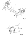
- the torsion beam axle 1 shown in FIG. 1 essentially comprises two wheel-guiding trailing arms 2, 3 and one the two trailing arms 2, 3 connecting cross member 4.
- the trailing arms 2, 3 are designed as tubular components.
- a bearing eye 5 is provided for elastic linkage to the vehicle body not shown here.
- shock absorbers 6 and springs 7 are also arranged.
- receptacles 8 are also connected to a wheel carrier Storage of a wheel provided.
- the cross member 4 consists of a tubular profile 9, the central region 10 (Torsion area) a torsionally soft cross section and both of them Ends 11, 12 have a torsionally rigid cross section.
- the transition areas from torsionally rigid to torsionally soft cross-section are fluid designed.
- one V- or U-shaped double-walled cross-section has an inner profile 13 and an outer profile 14, the one another along their legs 15, 16th contact areas and support each other.
- a friction-reducing additive A is applied.
- additive A comes preferably a mixture of mineral oils, synthetic oils, ceramic pigments, Petrol and sliding additives are used.
- the additive A is in the manufacturing process of the cross member 4 in liquid Shape has been introduced into the tubular profile 9. Then the tube profile 9 formed into the cross member 4 without cutting and colds the V- or U-shaped Cross-section. Additive A is liquid when applied. This will optimally wetted the inner surface of the tubular profile 9. After a short time Additive A changes its consistency and becomes pasty. This will be a Drainage avoided during further processing.
- Additive A contains hard constituents that form when the twist beam axle is loaded 1 in the contact area 17 in the surface of the cross member Press in 4 and create a surface with a low coefficient of friction here.
- Figures 3 and 4 show the cross member 18 of a further embodiment a twist beam axle 19.
- the one regarding his unspecified vertical central transverse plane symmetrical cross members 18 is welded with the ends 20 to longitudinal links 21 formed from tubes.
- the cross member 18 has one over the majority of its length L. V-shaped double-walled cross-section with an inner profile 22 and an outer profile 23.
- the cross member 18 is by non-cutting shaping of a round tube in cross section.
- At the ends 20 is the cross member 18 reshaped box-like without cutting.
- the end faces 24 of the box-like Ends 20 are connected to the longitudinal links 21 via circumferential weld seams connected.
- the ends 20 are enlarged in cross section, wherein it over the apex 25 of the cross member 18 towards the end the trailing arm 21 provided receptacles 26 for rubber bearings.
- the Apex 25 and in the middle between the legs 27, 28 of the outer profile 23 and inner profile 22 extending central longitudinal plane MLE with respect to the plane of symmetry extending through the longitudinal axes of the trailing arms 21 SE is arranged at an angle ⁇ .
- This angle ⁇ can vary depending on the desired driving characteristics of a motor vehicle in relation to its Rolling stiffness and the adjustment of track and camber on the wheel flange between 20 ° and 60 °, preferably 30 ° to 50 °.
- the inner profile 22 and the outer profile 23 are supported in the area of Vertex 25 and the adjoining legs 27, 28 against each other from. At least in the contact area 29 is a friction-reducing one Additive A applied. Additive A reduces friction in the contact area. There is no surface corrosion on the surfaces thus changed.
Landscapes
- Engineering & Computer Science (AREA)
- Mechanical Engineering (AREA)
- Vehicle Body Suspensions (AREA)
- Shafts, Cranks, Connecting Bars, And Related Bearings (AREA)
- Friction Gearing (AREA)
- Pressure Welding/Diffusion-Bonding (AREA)
- Recrystallisation Techniques (AREA)
Abstract
Description
- Figur 1
- eine perspektische Ansicht einer Verbundlenkerachse;
- Figur 2
- einen vertikalen Querschnitt durch den Querträger;
- Figur 3
- ebenfalls in perspektivischer Darstellung den Anbindungsbereich eines Querträgers einer Verbundlenkerachse für Kraftfahrzeuge an einen Längslenker;
- Figur 4
- einen Vertikalschnitt durch die Darstellung der Figur 2 entlang der Linie IV-IV und
- 1 -
- Verbundlenkerachse
- 2-
- Längslenker
- 3-
- Längslenker
- 4-
- Querträger
- 5-
- Lagerauge
- 6-
- Stoßdämpfer
- 7-
- Feder
- 8-
- Aufnahme
- 9-
- Rohrprofil
- 10-
- mittlerer Bereich von 4
- 11-
- Ende von 4
- 12-
- Ende von 4
- 13-
- Innenprofil
- 14-
- Außenprofil
- 15-
- Schenkel
- 16-
- Schenkel
- 17-
- Kontaktbereich
- 18-
- Querträger
- 19-
- Verbundlenkerachse
- 20-
- Ende von 18
- 21-
- Längslenker
- 22-
- Innenprofil
- 23-
- Außenprofil
- 24-
- Stirnseite v. 20
- 25-
- Scheitel von 18
- 26-
- Aufnahme
- 27-
- Schenkel
- 28-
- Schenkel
- 29-
- Kontaktbereich
- A -
- Additiv
- L-
- Länge von 18
- MLE-
- Mittellängsebene
- SE-
- Symmetrieebene
- α-
- Winkel zwischen MLE u. SE
Claims (5)
- Verbundlenkerachse für Kraftfahrzeuge, welche zwei durch einen Querträger (4; 18) verbundene Längslenker (2, 3; 21) aufweist, wobei der Querträger (4; 18) auf dem überwiegenden Teil seiner Länge einen V-oder U-förmigen doppelwandigen Querschnitt mit einem Innenprofil (13; 22) und einem Außenprofil (14; 23) besitzt, dadurch gekennzeichnet, dass sich das Außenprofil (14; 23) und das Innenprofil (13; 22) zumindest bereichsweise aneinander abstützen, wobei im Kontaktbereich (15; 29) zwischen Außenprofil (14; 23) und Innenprofil (13; 22) ein reibungsreduzierendes Additiv (A) aufgebracht ist.
- Verbundlenkerachse nach Anspruch 1, dadurch gekennzeichnet, dass das Additiv (A) keramischer Basis ist.
- Verbundlenkerachse nach Anspruch 1, dadurch gekennzeichnet, dass das Additiv (A) ein Metalloxid-Schmiermittel ist.
- Verbundlenkerachse nach einem der Ansprüche 1 bis 3, dadurch gekennzeichnet, dass das Additiv (A) temperaturbeständig ist.
- Verbundlenkerachse nach einem der Ansprüche 1 bis 4, dadurch gekennzeichnet, dass das Additiv (A) harte Bestandteile enthält, die sich unter Druck in die einander kontaktierenden Oberflächen des Kontaktbereichs eindrücken.
Applications Claiming Priority (2)
| Application Number | Priority Date | Filing Date | Title |
|---|---|---|---|
| DE20101602U DE20101602U1 (de) | 2001-01-31 | 2001-01-31 | Verbundlenkerachse |
| DE20101602U | 2001-01-31 |
Publications (3)
| Publication Number | Publication Date |
|---|---|
| EP1228906A2 true EP1228906A2 (de) | 2002-08-07 |
| EP1228906A3 EP1228906A3 (de) | 2003-07-16 |
| EP1228906B1 EP1228906B1 (de) | 2004-05-19 |
Family
ID=7952281
Family Applications (1)
| Application Number | Title | Priority Date | Filing Date |
|---|---|---|---|
| EP02001481A Expired - Lifetime EP1228906B1 (de) | 2001-01-31 | 2002-01-22 | Verbundlenkerachse |
Country Status (5)
| Country | Link |
|---|---|
| US (1) | US6616157B2 (de) |
| EP (1) | EP1228906B1 (de) |
| AT (1) | ATE267096T1 (de) |
| CZ (1) | CZ291420B6 (de) |
| DE (2) | DE20101602U1 (de) |
Cited By (2)
| Publication number | Priority date | Publication date | Assignee | Title |
|---|---|---|---|---|
| FR3021563A1 (fr) * | 2014-06-03 | 2015-12-04 | Peugeot Citroen Automobiles Sa | Procede de fabrication de pieces par emboutissage et/ou hydroformage apres placement de bande(s) antifriction entre parois |
| EP2977119A3 (de) * | 2014-07-10 | 2016-05-25 | Benteler Automobiltechnik GmbH | Verfahren zum herstellen eines torsionsprofils aus einer platine sowie torsionsprofil |
Families Citing this family (33)
| Publication number | Priority date | Publication date | Assignee | Title |
|---|---|---|---|---|
| DE10231377B3 (de) * | 2002-07-11 | 2004-01-15 | Daimlerchrysler Ag | Fahrzeugstarrachse mit integrierten Länglenkern |
| WO2005028221A1 (en) * | 2003-09-17 | 2005-03-31 | Hendrickson International Corporation | Rigid axle for a vehicle, comprising integrated trailing arms |
| DE10343583A1 (de) * | 2003-09-18 | 2005-04-14 | Bpw Bergische Achsen Kg | Verbundlenker-Fahrzeugachse in Bauart als ein- oder mehrteiliger Formkörper |
| WO2005095182A1 (ja) * | 2004-03-31 | 2005-10-13 | Honda Motor Co., Ltd. | 車両用サブフレーム及びブッシュ取付構造 |
| JP4211722B2 (ja) * | 2004-10-07 | 2009-01-21 | トヨタ自動車株式会社 | トーションビーム式サスペンション装置 |
| FR2878786B1 (fr) * | 2004-12-08 | 2007-02-23 | Auto Chassis Internat Snc Snc | Essieu souple comprenant une traverse a section tropezoidale, traverse, vehicule et procede de fabrication correspondants |
| WO2006095386A1 (ja) * | 2005-03-04 | 2006-09-14 | F.Tech Incorporation | トーションビーム式サスペンション |
| CN101107141A (zh) * | 2005-03-16 | 2008-01-16 | 麦格纳国际公司 | 带有整合式扭杆的扭转梁式车桥 |
| US20070246904A1 (en) * | 2005-09-12 | 2007-10-25 | Satoshi Murata | Torsion-Beam-Type Suspension Apparatus |
| US20070069496A1 (en) * | 2005-09-27 | 2007-03-29 | Rinehart Ronald A | Torsion beam suspension member |
| JP4344352B2 (ja) * | 2005-12-05 | 2009-10-14 | 本田技研工業株式会社 | トーションビーム式サスペンション |
| US7425006B2 (en) * | 2006-09-11 | 2008-09-16 | American Axle & Manufacturing, Inc. | Live twist beam axle assembly |
| DE102007050148A1 (de) * | 2007-07-09 | 2009-01-15 | Hyundai Motor Co. | Rohrträger für eine Torsionsträgerachsaufhängung |
| EP2020314A1 (de) * | 2007-08-01 | 2009-02-04 | GM Global Technology Operations, Inc. | Angetriebene Kraftfahrzeug-Hinterachse des Verbundlenkerachstyps |
| PL2183122T3 (pl) * | 2007-09-05 | 2013-03-29 | Magna Int Inc | Belka skrętna z blokadą |
| DE102008021155A1 (de) | 2008-04-28 | 2009-10-29 | Volkswagen Ag | Verfahren zur Herstellung einer Torsionskurbelachse in Schweißkonstruktion sowie Torsionskurbelachse |
| DE102008031123A1 (de) * | 2008-07-02 | 2010-01-07 | Bayerische Motoren Werke Aktiengesellschaft | Gegenlenkende Fahrzeug-Hinterachse |
| ITTO20080521A1 (it) * | 2008-07-08 | 2010-01-08 | Sistemi Sospensioni Spa | Traversa per una sospensione posteriore a ponte torcente per autoveicolo e procedimento per la sua fabbricazione |
| CA2644464C (en) * | 2008-10-17 | 2010-04-20 | Arcelormittal Tubular Products Canada Inc. | Twist-axle of variable wall thickness |
| WO2010124115A1 (en) * | 2009-04-22 | 2010-10-28 | V-Vehicle Company | Shear center raising twist axle with internal and tunable transitioning gussets |
| DE102009049117A1 (de) * | 2009-10-12 | 2011-04-14 | GM Global Technology Operations, Inc., Detroit | Reibgeschweißter Verbundlenker |
| US8322736B2 (en) * | 2011-02-18 | 2012-12-04 | Honda Motor Co., Ltd. | Swing arm assembly |
| EP2708294B1 (de) | 2012-09-13 | 2018-11-07 | Johannes Meier Werkzeugbau GmbH | Verfahren zur Herstellung eines Torsionsprofils |
| US9522588B2 (en) * | 2013-03-14 | 2016-12-20 | Magna International Inc. | Rear twist beam with bulged middle section |
| DE102014109453A1 (de) | 2014-07-07 | 2016-01-07 | Benteler Automobiltechnik Gmbh | Verfahren zum Herstellen eines Torsionsprofils aus einem rohrförmigen Hohlprofil sowie Torsionsprofil |
| DE102014221472A1 (de) * | 2014-10-22 | 2016-04-28 | Volkswagen Aktiengesellschaft | Querträger für eine Verbundlenkerachse |
| DE102015101474A1 (de) * | 2015-02-02 | 2016-08-04 | Benteler Automobiltechnik Gmbh | Achsanordnung mit modular festlegbarer Achseinstellung |
| DE102015212125A1 (de) | 2015-06-30 | 2017-01-05 | Ford Global Technologies, Llc | Torsionsquerträger, insbesondere für eine Verbundlenkerachse und Kraftfahrzeug aufweisend den Torsionsquerträger |
| DE102016210458B4 (de) | 2015-06-30 | 2022-03-31 | Ford Global Technologies, Llc | Torsionsquerträger, insbesondere für eine Verbundlenkerachse und Kraftfahrzeug aufweisend den Torsionsquerträger |
| DE202015103545U1 (de) | 2015-06-30 | 2015-07-23 | Ford Global Technologies, Llc | Torsionsquerträger, insbesondere für eine Verbundlenkerachse und Kraftfahrzeug aufweisend den Torsionsquerträger |
| IN201817018675A (de) * | 2016-03-30 | 2018-09-21 | Nippon Steel & Sumitomo Metal Corp | |
| KR102310505B1 (ko) * | 2017-06-28 | 2021-10-08 | 현대자동차주식회사 | 좌굴 유도 커플드 토션빔 액슬 및 차량 |
| DE102018100989B3 (de) | 2018-01-17 | 2019-02-14 | Benteler Automobiltechnik Gmbh | Verfahren zum Herstellen eines gebogenen Torsionsprofils sowie Torsionsprofil |
Citations (2)
| Publication number | Priority date | Publication date | Assignee | Title |
|---|---|---|---|---|
| FR2674987A1 (fr) | 1989-08-18 | 1992-10-09 | Osaulenko Nikolai | Ensemble de chauffage d'une cathode thermo-electronique pour dispositifs a faisceau d'electrons. |
| DE4416725A1 (de) | 1994-05-13 | 1995-11-16 | Opel Adam Ag | Kraftfahrzeug-Hinterachse |
Family Cites Families (10)
| Publication number | Priority date | Publication date | Assignee | Title |
|---|---|---|---|---|
| DE8315313U1 (de) | 1983-05-25 | 1984-08-09 | Adam Opel AG, 6090 Rüsselsheim | Hinterachse für Fahrzeuge, insbesondere Kraftfahrzeuge |
| US4790974A (en) * | 1987-11-30 | 1988-12-13 | Chrysler Motors Corporation | Method for manufacturing a vehicle cross-beam rear axle |
| FR2654987B1 (fr) * | 1989-11-29 | 1994-11-18 | Renault | Essieu souple pour vehicule automobile. |
| DE4330192B4 (de) * | 1992-09-16 | 2005-07-07 | Volkswagen Ag | Kraftfahrzeug-Hinterachse des Verbundlenkerachs-Typs |
| DE4447971B4 (de) * | 1994-05-13 | 2007-03-29 | GM Global Technology Operations, Inc., Detroit | Kraftfahrzeug-Hinterachse |
| FR2734207B1 (fr) * | 1995-05-19 | 1997-07-25 | Vallourec Vitry | Essieu semi-rigide pour vehicule |
| DE19823093C2 (de) * | 1998-05-22 | 2000-06-08 | Daimler Chrysler Ag | Vorrichtung zur Bestimmung von fahrzeugspezifischen Größen eines Fahrzeuges während der Fahrt |
| DE29809241U1 (de) * | 1998-05-26 | 1998-08-27 | Benteler Ag, 33104 Paderborn | Verbundlenkerachse |
| DE19910575A1 (de) * | 1999-03-10 | 2000-09-14 | Volkswagen Ag | Verbundlenkerachse |
| DE19911282A1 (de) * | 1999-03-13 | 2000-09-21 | Thyssen Krupp Automotive Gmbh | Verbundlenkerhinterachse |
-
2001
- 2001-01-31 DE DE20101602U patent/DE20101602U1/de not_active Expired - Lifetime
-
2002
- 2002-01-22 EP EP02001481A patent/EP1228906B1/de not_active Expired - Lifetime
- 2002-01-22 DE DE50200440T patent/DE50200440D1/de not_active Expired - Lifetime
- 2002-01-22 AT AT02001481T patent/ATE267096T1/de not_active IP Right Cessation
- 2002-01-28 US US10/058,648 patent/US6616157B2/en not_active Expired - Lifetime
- 2002-01-31 CZ CZ2002393A patent/CZ291420B6/cs not_active IP Right Cessation
Patent Citations (2)
| Publication number | Priority date | Publication date | Assignee | Title |
|---|---|---|---|---|
| FR2674987A1 (fr) | 1989-08-18 | 1992-10-09 | Osaulenko Nikolai | Ensemble de chauffage d'une cathode thermo-electronique pour dispositifs a faisceau d'electrons. |
| DE4416725A1 (de) | 1994-05-13 | 1995-11-16 | Opel Adam Ag | Kraftfahrzeug-Hinterachse |
Cited By (2)
| Publication number | Priority date | Publication date | Assignee | Title |
|---|---|---|---|---|
| FR3021563A1 (fr) * | 2014-06-03 | 2015-12-04 | Peugeot Citroen Automobiles Sa | Procede de fabrication de pieces par emboutissage et/ou hydroformage apres placement de bande(s) antifriction entre parois |
| EP2977119A3 (de) * | 2014-07-10 | 2016-05-25 | Benteler Automobiltechnik GmbH | Verfahren zum herstellen eines torsionsprofils aus einer platine sowie torsionsprofil |
Also Published As
| Publication number | Publication date |
|---|---|
| US20020105159A1 (en) | 2002-08-08 |
| ATE267096T1 (de) | 2004-06-15 |
| DE50200440D1 (de) | 2004-06-24 |
| CZ2002393A3 (cs) | 2002-09-11 |
| US6616157B2 (en) | 2003-09-09 |
| EP1228906B1 (de) | 2004-05-19 |
| DE20101602U1 (de) | 2001-04-05 |
| CZ291420B6 (cs) | 2003-03-12 |
| EP1228906A3 (de) | 2003-07-16 |
Similar Documents
| Publication | Publication Date | Title |
|---|---|---|
| EP1228906B1 (de) | Verbundlenkerachse | |
| EP1036679B1 (de) | Verbundlenkerhinterachse | |
| DE19653959C1 (de) | Querträger und Verfahren zum Herstellen eines Querträgers | |
| EP0916530B1 (de) | Verbundlenkerachse für Kraftfahrzeuge | |
| EP0681932B1 (de) | Kraftfahrzeug-Hinterachse | |
| EP0774369B1 (de) | Verbundlenker-Hinterachse | |
| EP2020314A1 (de) | Angetriebene Kraftfahrzeug-Hinterachse des Verbundlenkerachstyps | |
| EP1080953A1 (de) | Radaufhängung für Kraftfahrzeuge mit einer radführenden Blattfeder | |
| DE102009043552A1 (de) | Dämpfungsbuchse für Verbundlenkerhinterachse eines Kraftfahrzeuges | |
| DE19630647A1 (de) | Federbeinaufnahme für ein Kraftfahrzeug, insbesondere Personenkraftwagen | |
| DE4003922C2 (de) | ||
| DE102016007367A1 (de) | Starres Fahrwerk für Nutzfahrzeuge | |
| DE102019201518A1 (de) | Fahrzeugstarrachse und Verfahren zu deren Herstellung | |
| DE2027885B2 (de) | Radaufhängung für Kraftfahrzeuge | |
| EP1080954A2 (de) | Querträger als Bestandteil einer Verbundlenkerachse | |
| EP1541393B1 (de) | Torsionsachse | |
| DE102004009722A1 (de) | Radführungslenker | |
| EP1160108B1 (de) | Verbundlenkerachse | |
| WO2005044603A1 (de) | Verbundlenkerachse und verfahren zur herstellung eines querträgers | |
| WO2004110796A1 (de) | Wattstrebe | |
| DE19604286C1 (de) | Verbundlenkerachse für Kraftfahrzeuge | |
| DE2751997A1 (de) | Starrachse fuer fahrzeuge | |
| DE19542105B4 (de) | Verbundlenker- oder Koppellenkerachse | |
| DE102016123256B4 (de) | Querlenker sowie Verfahren zur Herstellung eines Querlenkers | |
| DE19535923B4 (de) | Unabhängige Radaufhängung für angetriebene Hinterräder von Kraftfahrzeugen |
Legal Events
| Date | Code | Title | Description |
|---|---|---|---|
| PUAI | Public reference made under article 153(3) epc to a published international application that has entered the european phase |
Free format text: ORIGINAL CODE: 0009012 |
|
| AK | Designated contracting states |
Kind code of ref document: A2 Designated state(s): AT BE CH CY DE DK ES FI FR GB GR IE IT LI LU MC NL PT SE TR |
|
| AX | Request for extension of the european patent |
Free format text: AL;LT;LV;MK;RO;SI |
|
| PUAL | Search report despatched |
Free format text: ORIGINAL CODE: 0009013 |
|
| AK | Designated contracting states |
Designated state(s): AT BE CH CY DE DK ES FI FR GB GR IE IT LI LU MC NL PT SE TR |
|
| AX | Request for extension of the european patent |
Extension state: AL LT LV MK RO SI |
|
| 17P | Request for examination filed |
Effective date: 20030611 |
|
| GRAP | Despatch of communication of intention to grant a patent |
Free format text: ORIGINAL CODE: EPIDOSNIGR1 |
|
| GRAS | Grant fee paid |
Free format text: ORIGINAL CODE: EPIDOSNIGR3 |
|
| RAP1 | Party data changed (applicant data changed or rights of an application transferred) |
Owner name: BENTELER AUTOMOBILTECHNIK GMBH |
|
| GRAA | (expected) grant |
Free format text: ORIGINAL CODE: 0009210 |
|
| AKX | Designation fees paid |
Designated state(s): AT BE CH CY DE DK ES FI FR GB GR IE IT LI LU MC NL PT SE TR |
|
| AK | Designated contracting states |
Kind code of ref document: B1 Designated state(s): AT BE CH CY DE DK ES FI FR GB GR IE IT LI LU MC NL PT SE TR |
|
| PG25 | Lapsed in a contracting state [announced via postgrant information from national office to epo] |
Ref country code: TR Free format text: LAPSE BECAUSE OF FAILURE TO SUBMIT A TRANSLATION OF THE DESCRIPTION OR TO PAY THE FEE WITHIN THE PRESCRIBED TIME-LIMIT Effective date: 20040519 Ref country code: NL Free format text: LAPSE BECAUSE OF FAILURE TO SUBMIT A TRANSLATION OF THE DESCRIPTION OR TO PAY THE FEE WITHIN THE PRESCRIBED TIME-LIMIT Effective date: 20040519 Ref country code: IE Free format text: LAPSE BECAUSE OF FAILURE TO SUBMIT A TRANSLATION OF THE DESCRIPTION OR TO PAY THE FEE WITHIN THE PRESCRIBED TIME-LIMIT Effective date: 20040519 Ref country code: FI Free format text: LAPSE BECAUSE OF FAILURE TO SUBMIT A TRANSLATION OF THE DESCRIPTION OR TO PAY THE FEE WITHIN THE PRESCRIBED TIME-LIMIT Effective date: 20040519 Ref country code: GB Free format text: LAPSE BECAUSE OF FAILURE TO SUBMIT A TRANSLATION OF THE DESCRIPTION OR TO PAY THE FEE WITHIN THE PRESCRIBED TIME-LIMIT Effective date: 20040519 |
|
| REG | Reference to a national code |
Ref country code: GB Ref legal event code: FG4D Free format text: NOT ENGLISH |
|
| REG | Reference to a national code |
Ref country code: CH Ref legal event code: EP |
|
| REG | Reference to a national code |
Ref country code: IE Ref legal event code: FG4D Free format text: GERMAN |
|
| REF | Corresponds to: |
Ref document number: 50200440 Country of ref document: DE Date of ref document: 20040624 Kind code of ref document: P |
|
| PG25 | Lapsed in a contracting state [announced via postgrant information from national office to epo] |
Ref country code: SE Free format text: LAPSE BECAUSE OF FAILURE TO SUBMIT A TRANSLATION OF THE DESCRIPTION OR TO PAY THE FEE WITHIN THE PRESCRIBED TIME-LIMIT Effective date: 20040819 Ref country code: DK Free format text: LAPSE BECAUSE OF FAILURE TO SUBMIT A TRANSLATION OF THE DESCRIPTION OR TO PAY THE FEE WITHIN THE PRESCRIBED TIME-LIMIT Effective date: 20040819 Ref country code: GR Free format text: LAPSE BECAUSE OF FAILURE TO SUBMIT A TRANSLATION OF THE DESCRIPTION OR TO PAY THE FEE WITHIN THE PRESCRIBED TIME-LIMIT Effective date: 20040819 |
|
| PG25 | Lapsed in a contracting state [announced via postgrant information from national office to epo] |
Ref country code: ES Free format text: LAPSE BECAUSE OF FAILURE TO SUBMIT A TRANSLATION OF THE DESCRIPTION OR TO PAY THE FEE WITHIN THE PRESCRIBED TIME-LIMIT Effective date: 20040830 |
|
| NLV1 | Nl: lapsed or annulled due to failure to fulfill the requirements of art. 29p and 29m of the patents act | ||
| GBV | Gb: ep patent (uk) treated as always having been void in accordance with gb section 77(7)/1977 [no translation filed] |
Effective date: 20040519 |
|
| REG | Reference to a national code |
Ref country code: IE Ref legal event code: FD4D |
|
| ET | Fr: translation filed | ||
| PG25 | Lapsed in a contracting state [announced via postgrant information from national office to epo] |
Ref country code: IT Free format text: LAPSE BECAUSE OF NON-PAYMENT OF DUE FEES Effective date: 20050122 Ref country code: CY Free format text: LAPSE BECAUSE OF FAILURE TO SUBMIT A TRANSLATION OF THE DESCRIPTION OR TO PAY THE FEE WITHIN THE PRESCRIBED TIME-LIMIT Effective date: 20050122 Ref country code: LU Free format text: LAPSE BECAUSE OF NON-PAYMENT OF DUE FEES Effective date: 20050122 |
|
| PG25 | Lapsed in a contracting state [announced via postgrant information from national office to epo] |
Ref country code: MC Free format text: LAPSE BECAUSE OF NON-PAYMENT OF DUE FEES Effective date: 20050131 Ref country code: AT Free format text: LAPSE BECAUSE OF NON-PAYMENT OF DUE FEES Effective date: 20050131 Ref country code: BE Free format text: LAPSE BECAUSE OF NON-PAYMENT OF DUE FEES Effective date: 20050131 |
|
| PLBE | No opposition filed within time limit |
Free format text: ORIGINAL CODE: 0009261 |
|
| STAA | Information on the status of an ep patent application or granted ep patent |
Free format text: STATUS: NO OPPOSITION FILED WITHIN TIME LIMIT |
|
| 26N | No opposition filed |
Effective date: 20050222 |
|
| BERE | Be: lapsed |
Owner name: *BENTELER AUTOMOBILTECHNIK G.M.B.H. Effective date: 20050131 |
|
| PG25 | Lapsed in a contracting state [announced via postgrant information from national office to epo] |
Ref country code: CH Free format text: LAPSE BECAUSE OF NON-PAYMENT OF DUE FEES Effective date: 20060131 Ref country code: LI Free format text: LAPSE BECAUSE OF NON-PAYMENT OF DUE FEES Effective date: 20060131 |
|
| REG | Reference to a national code |
Ref country code: CH Ref legal event code: PL |
|
| BERE | Be: lapsed |
Owner name: *BENTELER AUTOMOBILTECHNIK G.M.B.H. Effective date: 20050131 |
|
| PG25 | Lapsed in a contracting state [announced via postgrant information from national office to epo] |
Ref country code: PT Free format text: LAPSE BECAUSE OF NON-PAYMENT OF DUE FEES Effective date: 20041019 |
|
| PGRI | Patent reinstated in contracting state [announced from national office to epo] |
Ref country code: IT Effective date: 20091201 |
|
| REG | Reference to a national code |
Ref country code: FR Ref legal event code: PLFP Year of fee payment: 14 |
|
| REG | Reference to a national code |
Ref country code: FR Ref legal event code: PLFP Year of fee payment: 15 |
|
| REG | Reference to a national code |
Ref country code: FR Ref legal event code: PLFP Year of fee payment: 16 |
|
| REG | Reference to a national code |
Ref country code: FR Ref legal event code: PLFP Year of fee payment: 17 |
|
| PGFP | Annual fee paid to national office [announced via postgrant information from national office to epo] |
Ref country code: FR Payment date: 20210121 Year of fee payment: 20 |
|
| PGFP | Annual fee paid to national office [announced via postgrant information from national office to epo] |
Ref country code: DE Payment date: 20210127 Year of fee payment: 20 |
|
| PGFP | Annual fee paid to national office [announced via postgrant information from national office to epo] |
Ref country code: IT Payment date: 20210121 Year of fee payment: 20 |
|
| REG | Reference to a national code |
Ref country code: DE Ref legal event code: R071 Ref document number: 50200440 Country of ref document: DE |