EP1231393A1 - Gleitelement mit niedriger Reibung für eine hin-und hergehende Maschine - Google Patents
Gleitelement mit niedriger Reibung für eine hin-und hergehende Maschine Download PDFInfo
- Publication number
- EP1231393A1 EP1231393A1 EP02001524A EP02001524A EP1231393A1 EP 1231393 A1 EP1231393 A1 EP 1231393A1 EP 02001524 A EP02001524 A EP 02001524A EP 02001524 A EP02001524 A EP 02001524A EP 1231393 A1 EP1231393 A1 EP 1231393A1
- Authority
- EP
- European Patent Office
- Prior art keywords
- sliding
- sliding element
- contact surface
- low friction
- recesses
- Prior art date
- Legal status (The legal status is an assumption and is not a legal conclusion. Google has not performed a legal analysis and makes no representation as to the accuracy of the status listed.)
- Granted
Links
- 239000010687 lubricating oil Substances 0.000 claims description 15
- 230000003247 decreasing effect Effects 0.000 claims description 4
- 239000003921 oil Substances 0.000 description 36
- 230000000694 effects Effects 0.000 description 23
- 230000014759 maintenance of location Effects 0.000 description 7
- 230000000052 comparative effect Effects 0.000 description 6
- 239000010705 motor oil Substances 0.000 description 6
- 230000003746 surface roughness Effects 0.000 description 5
- 238000005516 engineering process Methods 0.000 description 3
- VYZAMTAEIAYCRO-UHFFFAOYSA-N Chromium Chemical compound [Cr] VYZAMTAEIAYCRO-UHFFFAOYSA-N 0.000 description 2
- 230000000573 anti-seizure effect Effects 0.000 description 2
- 239000000314 lubricant Substances 0.000 description 2
- 230000001050 lubricating effect Effects 0.000 description 2
- 238000005461 lubrication Methods 0.000 description 2
- 239000002184 metal Substances 0.000 description 2
- 229910052751 metal Inorganic materials 0.000 description 2
- 238000007747 plating Methods 0.000 description 2
- 229910001018 Cast iron Inorganic materials 0.000 description 1
- 229910000831 Steel Inorganic materials 0.000 description 1
- 239000008186 active pharmaceutical agent Substances 0.000 description 1
- 230000005540 biological transmission Effects 0.000 description 1
- 230000006866 deterioration Effects 0.000 description 1
- 238000010586 diagram Methods 0.000 description 1
- 239000012530 fluid Substances 0.000 description 1
- 239000000446 fuel Substances 0.000 description 1
- 238000000034 method Methods 0.000 description 1
- 238000012986 modification Methods 0.000 description 1
- 230000004048 modification Effects 0.000 description 1
- 230000000717 retained effect Effects 0.000 description 1
- 102200003959 rs11556986 Human genes 0.000 description 1
- 239000010959 steel Substances 0.000 description 1
Images


Classifications
-
- F—MECHANICAL ENGINEERING; LIGHTING; HEATING; WEAPONS; BLASTING
- F02—COMBUSTION ENGINES; HOT-GAS OR COMBUSTION-PRODUCT ENGINE PLANTS
- F02F—CYLINDERS, PISTONS OR CASINGS, FOR COMBUSTION ENGINES; ARRANGEMENTS OF SEALINGS IN COMBUSTION ENGINES
- F02F1/00—Cylinders; Cylinder heads
- F02F1/18—Other cylinders
- F02F1/20—Other cylinders characterised by constructional features providing for lubrication
-
- F—MECHANICAL ENGINEERING; LIGHTING; HEATING; WEAPONS; BLASTING
- F02—COMBUSTION ENGINES; HOT-GAS OR COMBUSTION-PRODUCT ENGINE PLANTS
- F02F—CYLINDERS, PISTONS OR CASINGS, FOR COMBUSTION ENGINES; ARRANGEMENTS OF SEALINGS IN COMBUSTION ENGINES
- F02F1/00—Cylinders; Cylinder heads
- F02F1/02—Cylinders; Cylinder heads having cooling means
- F02F1/10—Cylinders; Cylinder heads having cooling means for liquid cooling
-
- F—MECHANICAL ENGINEERING; LIGHTING; HEATING; WEAPONS; BLASTING
- F16—ENGINEERING ELEMENTS AND UNITS; GENERAL MEASURES FOR PRODUCING AND MAINTAINING EFFECTIVE FUNCTIONING OF MACHINES OR INSTALLATIONS; THERMAL INSULATION IN GENERAL
- F16C—SHAFTS; FLEXIBLE SHAFTS; ELEMENTS OR CRANKSHAFT MECHANISMS; ROTARY BODIES OTHER THAN GEARING ELEMENTS; BEARINGS
- F16C29/00—Bearings for parts moving only linearly
- F16C29/02—Sliding-contact bearings
-
- F—MECHANICAL ENGINEERING; LIGHTING; HEATING; WEAPONS; BLASTING
- F16—ENGINEERING ELEMENTS AND UNITS; GENERAL MEASURES FOR PRODUCING AND MAINTAINING EFFECTIVE FUNCTIONING OF MACHINES OR INSTALLATIONS; THERMAL INSULATION IN GENERAL
- F16C—SHAFTS; FLEXIBLE SHAFTS; ELEMENTS OR CRANKSHAFT MECHANISMS; ROTARY BODIES OTHER THAN GEARING ELEMENTS; BEARINGS
- F16C33/00—Parts of bearings; Special methods for making bearings or parts thereof
- F16C33/02—Parts of sliding-contact bearings
- F16C33/04—Brasses; Bushes; Linings
- F16C33/06—Sliding surface mainly made of metal
- F16C33/10—Construction relative to lubrication
- F16C33/1025—Construction relative to lubrication with liquid, e.g. oil, as lubricant
- F16C33/106—Details of distribution or circulation inside the bearings, e.g. details of the bearing surfaces to affect flow or pressure of the liquid
- F16C33/1065—Grooves on a bearing surface for distributing or collecting the liquid
Definitions
- the present invention relates to a friction reduction technology for machine parts which aims at reducing friction by forming microscopic recesses on a sliding contact surface of the machine parts. Specifically, this invention relates to a low friction element capable of reducing friction loss in engine parts for automobiles.
- a lubricating oil film formed on the sliding contact surface is subjected to shear strain at high speed at microscopic projections formed between the recesses. This causes shear loss in the oil film to thereby increase friction loss.
- the sliding velocity becomes zero at both ends of the sliding stroke, namely, a turning point of the reciprocating motion of the sliding element. Therefore, at the both ends of the sliding stroke, the lubricating oil is prevented from being brought onto the sliding contact surface and allowed to run away through the recesses. This causes lack of the oil on the sliding contact surface, so that the effect of friction reduction is restricted.
- An object of the present invention is to provide a low friction sliding element capable of reducing friction loss at a mid-point of the sliding stroke and preventing lack of lubricating oil at both ends of the sliding stroke, which can be utilized for reciprocating parts of engines, for instance, a piston, a cylinder wall and a valve lifter.
- a low friction sliding element for cooperating with a counterpart to make a relative sliding motion, the sliding element comprising:
- each of the plateaus of the sliding contact surface of the sliding element of the present invention has a surface having an arithmetical mean roughness Ra of not more than 0.3 ⁇ m.
- the arithmetical mean roughness Ra may be not less than 0.01 ⁇ m.
- the arithmetical mean roughness Ra is prescribed in JIS B 0601-1994.
- the sliding contact surface of the sliding element is adapted to be lubricated with a lubricating oil. Further, a ratio of a maximum depth of the recesses of the sliding contact surface of the sliding element to a minimum depth of the recesses thereof may be not less than two.
- the predetermined direction in which the depths of the recesses regularly vary may be a sliding direction of the sliding element.
- the recesses of the sliding contact surface of the sliding element of the present invention may be in the form of grooves extending perpendicular to the sliding direction of the sliding element.
- the recesses and the plateaus have widths extending on a center line of a roughness curve of the sliding contact surface, respectively.
- a ratio of the width of each recess to the width of each plateau may be not less than 1/10.
- the ratio of the width of the recess to the width of the plateau may be within a range of 1/5 to 5 at a predetermined portion of the sliding contact surface in which maximum sliding friction is caused.
- the predetermined portion of the sliding contact surface corresponds to a mid-point of a stroke of the sliding element.
- a ratio of a maximum depth of the recesses to a thickness of the lubricating oil film formed on the plateaus is preferably within a range of 2 to 10 at the predetermined portion of the sliding contact surface.
- the maximum depth of the recesses may be within a range of 5 to 30 ⁇ m.
- the depths of the recesses may be maximum at the predetermined portion of the sliding contact surface, and be gradually decreased as the recesses are further apart from the predetermined portion of the sliding contact surface.
- the recesses may be formed between opposed end portions of the sliding contact surface which are located in the predetermined direction, and the depths of the recesses may be gradually increased from near the opposed ends of the sliding contact surface toward the predetermined portion of the sliding contact surface.
- the opposed end portions of the sliding contact surface may correspond to both ends of the stroke of the sliding element.
- a sliding contact surface of the counterpart may have an arithmetical mean roughness Ra of not more than 0.3 ⁇ m.
- the arithmetical mean roughness Ra of the sliding contact surface of the counterpart is not less than 0.1 ⁇ m.
- the sliding element of the present invention may be applied to engine parts including a piston skirt for an engine, an engine cylinder wall defining a cylinder bore, a cylinder liner for an engine cylinder, and a valve lifter for an engine valve.
- Fig. 1 is a schematic perspective view of a microstructure of a sliding contact surface of a low friction sliding element of a preferred embodiment of the present invention
- Fig. 2 is a schematic explanatory diagram showing procedure of a reciprocating slide test for evaluating the effect of friction reduction of the sliding element of the embodiment of the invention
- Fig. 3 is a front view of an engine piston
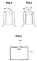
- Fig. 4 is a vertical section of an engine cylinder wall
- Fig. 5 is a vertical section of a cylinder liner fixed to an engine cylinder
- Fig. 6 is a vertical section of a valve lifter for an engine valve.
- the low friction sliding element has a sliding contact surface that is in sliding contact with a sliding contact surface of a counterpart via lubricating oil during relative sliding motion of the sliding element and the counterpart.
- the sliding contact surface of the low friction sliding element has a microstructure that is adapted to exhibit a significant friction-reduction effect under relatively good lubricating condition, as compared with a so-called smooth sliding contact surface generally considered to have a minimum friction coefficient.
- the low friction sliding element of the embodiment has sliding contact surface 1 having a plurality of microscopic recesses 2 and a plurality of plateaus 3 interrupted by recesses 2, 2. Namely, recess 2 and plateau 3 are alternately arranged. Plateaus 3 have flat top surfaces flush with each other. Recesses 2 have depths regularly varying in sliding direction SD of the sliding element relative to a counterpart (not shown). Here, the depth of each recess 2 means a distance between a bottom of recess 2 and an imaginary plane formed by top surfaces of plateaus 3. Specifically, as shown in Fig.
- recesses 2 have maximum depth Dd, minimum depth Ds and medium depths Dm1, Dm2 between maximum and minimum depths Dd and Ds gradually varying in sliding direction SD.
- Recesses 2 have function of retaining the lubricating oil. With the arrangement of recesses 2, sliding contact surface 1 can ensure the oil retention capacity and the thickness of the oil film formed thereon at optimal values corresponding to change in sliding velocity of the sliding element or shear rate of the oil film. Therefore, friction caused on sliding contact surface 1 can be significantly reduced as compared with an extremely smooth sliding contact surface formed by superfinishing.
- each plateau 3 preferably has an arithmetical mean roughness Ra of not more than 0.3 ⁇ m.
- the arithmetical mean roughness Ra is prescribed in JIS B 0601-1994. If the top surface of plateau 3 has an arithmetical mean roughness Ra of more than 0.3 ⁇ m, there will occur metal-to-metal contact between sliding contact surface 1 and the sliding contact surface of the counterpart when the sliding element slidingly moves relative to the counterpart. This causes deterioration of the effect of friction reduction.
- top surface of plateau 3 has an arithmetical mean roughness Ra of less than 0.01 ⁇ m, the effect of friction reduction will not be enhanced more than the case of the arithmetical mean roughness Ra ranging from 0.01 ⁇ m to 0.3 ⁇ m.
- a lubricating oil for lubricating the low friction sliding element of the invention may be an engine oil and a transmission oil.
- the sliding element can exhibit the effect of friction reduction upon being lubricated with the lubricating oil.
- a ratio of maximum depth Dd of recesses 2 to minimum depth Ds of recesses 2 is preferably not less than two from the viewpoint of improvement in friction reduction. If the ratio of maximum depth Dd to minimum depth Ds is less than two, maximum depth Dd and minimum depth Ds are closer to each other. In this case, if minimum depth Ds and maximum depth Dd are relatively small, the effect of friction reduction will not be explicitly exhibited at a mid-point of the sliding stroke where the sliding velocity becomes high. Conversely, if minimum depth Ds and maximum depth Dd are relatively large, the oil film will be eliminated at both ends of the sliding stroke. Furthermore, even if the ratio of maximum depth Dd to minimum depth Ds is not less than ten, the effect of friction reduction cannot be further improved though it depends on sliding condition of the sliding element or absolute value of maximum depth Dd.
- recesses 2 separated from each other are in the form of grooves extending in a direction perpendicular to sliding direction SD as shown in Fig. 1.
- Groove-shaped recesses 2 can serve for facilitating discharge of the lubricating oil at the mid-point of the sliding stroke where the sliding velocity becomes high. The effect of friction reduction, therefore, can be enhanced as a whole.
- the oil is allowed to be brought onto plateaus 3 upon sliding motion of the sliding element relative to the counterpart. This can provide stable fluid lubrication to the sliding element under engine operation condition varying from low-speed range to high-speed range.
- an engine oil can be retained by the grooves of the sliding contact surface thereof and the oil film can be stably formed on the plateaus of the sliding contact surface thereof.
- This can prevent seizure of the sliding contact surface of the piston skirt or the cylinder wall relative to the corresponding sliding contact surface of a counterpart, namely, an engine cylinder wall or an engine piston skirt.
- the piston skirt or the cylinder wall to which the sliding element of the present invention is applied can exhibit excellent anti-seizure property.
- Each recess 2 formed into a groove has width Wg extending on center line C of a roughness curve of sliding contact surface 1.
- Each plateau 3 has width Wh extending on center line C of the roughness curve of sliding contact surface 1.
- Ratio Wg/Wh of width Wg of recess (groove) 2 to width Wh of plateau 3 is preferably not less than 1/10. If ratio Wg/Wh is less than 1/10, the oil retention effect of the grooves and the oil discharge effect thereof cannot be sufficiently obtained so that the effect of friction reduction will decrease. Further, ratio Wg/Wh may be within a range of 1/5 to 5 at a predetermined portion of the sliding contact surface in which maximum sliding friction is caused.
- the maximum sliding friction is caused at the mid-point of the sliding stroke where the sliding speed becomes high. If ratio Wg/Wh is less than 1/5 at the mid-point of the sliding stroke, the oil retention effect and the oil discharge effect cannot be sufficiently obtained. If ratio Wg/Wh exceeds 1/5 at the mid-point of the sliding stroke, load-resistant capability of plateaus 3 will be deteriorated to thereby cause wear on plateaus 3.
- Ratio Dd/hc of maximum depth Dd of recesses (grooves) 2 to thickness hc of a lubricating oil film formed on plateaus 3 may be within a range of 2 to 10 at the predetermined portion of the sliding contact surface where maximum sliding friction is caused.
- thickness hc is a calculated value of thickness of the lubricating oil film formed on plateaus 3. Owing to the relationship between maximum depth Dd of recesses (grooves) 2 and thickness hc of the oil film, discharge of the oil can be suitably controlled to thereby enhance the effect of friction reduction of the sliding element. If ratio Dd/hc is less than 2, the oil discharge effect will be deteriorated to thereby lessen the effect of friction reduction.
- maximum depth Dd of recesses (grooves) 2 may be within a range of 5 to 30 ⁇ m. If maximum depth Dd of recesses (grooves) 2 is smaller than 5 ⁇ m, the oil retention effect and the oil discharge effect will be deteriorated so that the effect of friction reduction will be lessened. If maximum depth Dd of recesses (grooves) 2 is larger than 30 ⁇ m, the oil discharge amount will excessively increase to thereby cause an insufficient thickness of the oil film formed on plateaus 3.
- ratio Dd/hc may be given high priority.
- recesses (grooves) 2 are formed between opposed end portions of the sliding contact surface which are located in sliding direction SD.
- the opposed end portions of the sliding contact surface correspond to both ends of the sliding stroke.
- Recesses (grooves) 2 are preferably positioned slightly inside the opposed end portions of the sliding contact surface. This is because a sliding tangent, that means a tangent to the sliding contact surface in the sliding direction, terminates at the both ends of the sliding stroke so that the oil film is prevented from being brought to the opposed end portions of the sliding contact surface. This causes wear at the opposed end portions of the sliding contact surface.
- the depths of recesses (grooves) 2 are maximum at the predetermined portion of the sliding contact surface which corresponds to the mid-point of the sliding stroke, and are gradually decreased as recesses (grooves) 2 are further apart from the predetermined portion of the sliding contact surface. Namely, the depths of the recesses (grooves) 2 are gradually increased from one of the opposed end portions of the sliding contact surface toward the predetermined portion of the sliding contact surface and then gradually decreased toward the other of the opposed end portions thereof. This is because the sliding speed of the sliding tangent gradually becomes high toward the mid-point of the sliding stroke.
- the sliding element may be used in combination with a counterpart having a sliding contact surface having an arithmetical mean roughness Ra of not more than 0.3 ⁇ m. If the arithmetical mean roughness Ra is larger than 0.3 ⁇ m, metal-to-metal contact between the sliding contact surfaces will be caused depending on friction condition. Although the arithmetical mean roughness Ra is preferably smaller, the effect of friction reduction will not be further enhanced even when the arithmetical mean roughness Ra is smaller than 0.1 ⁇ m.
- the sliding element of the present invention can be applied to various engine parts including a piston skirt, a cylinder wall defining a cylinder bore, a cylinder liner and a valve lifter.
- Fig. 3 shows piston skirt 110 of engine piston 100.
- Fig. 4 shows cylinder wall 210 of engine cylinder block 200 which defines cylinder bore 212.
- Fig. 5 shows cylinder liner 300 fixed into cylinder bore 212 and having sliding contact surface 310.
- Fig. 6 shows valve lifter 400 having side wall 410 having a sliding contact surface.
- Engine parts to which the sliding element of the present invention is applicable are not limited to those shown in Figs. 3-6. Owing to the application to engine parts, friction loss and wear magnitude caused in the engine can be reduced, so that engine performance can be better maintained for a relatively long period and engine fuel economy can be remarkably improved.
- Specimens of a sliding element were prepared using pieces of a flat sheet made of cast iron generally used for forming an engine cylinder wall. The pieces were subjected to grinding, surface microscopic recessing, and lapping while changing the working conditions to form a sliding contact surface having properties shown in Table 1.
- the properties of the sliding contact surface include surface roughness Ra of the plateau top surface, ratio Dd/Ds of maximum depth Dd of the grooves to minimum depth Ds thereof, ratio Wg/Wh of groove width Wg extending on the center line of the roughness curve of the sliding contact surface to plateau width Wh extending on the center line thereof, and ratio Dd/hc of maximum depth Dd of the grooves to calculated thickness hc of the oil film formed at the mid-point of the sliding stroke.
- microscopic grooves as indicated at 2 in Fig. 1 were formed perpendicular to the sliding direction and configured in such a manner that the depths were minimum at both ends of the sliding stroke and gradually increased toward the mid-point of the sliding stroke.
- specimen T was in contact with counterpart P having a generally U-shaped contour in section.
- Counterpart P had a curvature R30 at a tip end thereof and a chrome plating adapted for a piston ring.
- specimen T was slided relative to counterpart P in such a manner that the sliding contact surface of specimen T came into line contact with a surface of counterpart P.
- the test conditions were as follows.
- Specimens were prepared in the same manner as described in Examples 1-16 except that the sliding contact surface of the specimen of Comparative Example 1 was a smooth surface having no groove, and that the sliding contact surface of the specimen of Comparative Example 2 had a cross-hatched microstructure in which V-shaped grooves having substantially same depth were formed.
- the thus-prepared specimens were subjected to the sliding friction test in the same manner and the same conditions as described in Examples 1-16. The test results are shown in Table 1.
- the sliding contact surface of the sliding element of Example 12 had a surface roughness of the plateau top surface which was larger than that of Example 1 because the sliding contact surface was not subjected to lapping. Due to the larger surface roughness of the plateau top surface, the sliding contact surface had scuffing and a relatively high friction coefficient. Further, it was found that ratio Dd/Ds of maximum depth Dd of the grooves to minimum depth Ds thereof in the sliding contact surface of the sliding element of Example 13 was the relatively small value, i.e. 1.5, so that the friction coefficient at the mid-point of the sliding stroke was slightly large.
- Example 13 it was noted that the depth of the grooves located near both ends of the sliding stroke at which the sliding speed was low and the oil film tended to be eliminated, was slightly large, i.e., approximately 10 ⁇ m, to thereby readily discharge the oil therefrom. As a result, scuffing was slightly caused in the sliding contact surface.
- Example 14 ratio Wg/Wh of groove width Wg extending on the center line of the roughness curve of the sliding contact surface to plateau width Wh extending on the center line thereof was relatively small, so that the friction coefficient was slightly large.
- ratio Dd/hc of maximum depth Dd of the grooves to calculated thickness hc of the oil film formed at the mid-point of the sliding stroke was slightly small.
- An absolute value of maximum depth Dd of the grooves was relatively small, i.e., 3 ⁇ m.
- the friction coefficient was slightly large.
- maximum depth Dd of the grooves was relatively large, i.e., 40 ⁇ m, so that the friction coefficient at the mid-point of the sliding stroke was slightly large.
Landscapes
- Engineering & Computer Science (AREA)
- General Engineering & Computer Science (AREA)
- Mechanical Engineering (AREA)
- Chemical & Material Sciences (AREA)
- Combustion & Propulsion (AREA)
- Oil, Petroleum & Natural Gas (AREA)
- Pistons, Piston Rings, And Cylinders (AREA)
- Valve-Gear Or Valve Arrangements (AREA)
- Cylinder Crankcases Of Internal Combustion Engines (AREA)
Applications Claiming Priority (2)
| Application Number | Priority Date | Filing Date | Title |
|---|---|---|---|
| JP2001033277A JP3712052B2 (ja) | 2001-02-09 | 2001-02-09 | 低摩擦摺動部材 |
| JP2001033277 | 2001-02-09 |
Publications (2)
| Publication Number | Publication Date |
|---|---|
| EP1231393A1 true EP1231393A1 (de) | 2002-08-14 |
| EP1231393B1 EP1231393B1 (de) | 2006-11-29 |
Family
ID=18897055
Family Applications (1)
| Application Number | Title | Priority Date | Filing Date |
|---|---|---|---|
| EP02001524A Expired - Lifetime EP1231393B1 (de) | 2001-02-09 | 2002-01-22 | Gleitelement mit niedriger Reibung für eine hin-und hergehende Maschine |
Country Status (4)
| Country | Link |
|---|---|
| US (1) | US6736101B2 (de) |
| EP (1) | EP1231393B1 (de) |
| JP (1) | JP3712052B2 (de) |
| DE (1) | DE60216340T2 (de) |
Cited By (7)
| Publication number | Priority date | Publication date | Assignee | Title |
|---|---|---|---|---|
| GB2391274A (en) * | 2002-07-05 | 2004-02-04 | Daimler Chrysler Ag | Production of lubricant reservoirs in a slide surface |
| EP1701051A1 (de) * | 2005-03-09 | 2006-09-13 | Ab Skf | Gleitlager mit unterschiedlichen Hohlraumgruppierungen |
| EP1921356A1 (de) * | 2006-11-09 | 2008-05-14 | Carl Freudenberg KG | Gleitringdichtung, Gleitringdichtungsanordnung und deren Verwendung |
| EP1730396B1 (de) * | 2004-03-15 | 2019-05-08 | Tenneco Inc. | Zylinderlaufflächen aus hochfestem stahl für dieselmotoren |
| CN110219878A (zh) * | 2019-06-13 | 2019-09-10 | 天津大学 | 一种全工况复合摩擦副结构 |
| CN110273921A (zh) * | 2019-06-13 | 2019-09-24 | 天津大学 | 一种全工况复合结构滑动轴承 |
| GB2577505A (en) * | 2018-09-26 | 2020-04-01 | Ford Global Tech Llc | A bore portion for receiving a reciprocating piston |
Families Citing this family (48)
| Publication number | Priority date | Publication date | Assignee | Title |
|---|---|---|---|---|
| JP3555844B2 (ja) | 1999-04-09 | 2004-08-18 | 三宅 正二郎 | 摺動部材およびその製造方法 |
| US6739238B2 (en) | 2000-11-20 | 2004-05-25 | Nissan Motor Co., Ltd. | Sliding structure for a reciprocating internal combustion engine and a reciprocating internal combustion engine using the sliding structure |
| JP2003184883A (ja) | 2001-12-20 | 2003-07-03 | Nissan Motor Co Ltd | 軸受摺動部材 |
| JP3555891B2 (ja) * | 2002-02-22 | 2004-08-18 | 新日本石油株式会社 | 低摩擦摺動材料及びこれに用いる潤滑油組成物 |
| JP2004138128A (ja) | 2002-10-16 | 2004-05-13 | Nissan Motor Co Ltd | 自動車エンジン用摺動部材 |
| US6969198B2 (en) | 2002-11-06 | 2005-11-29 | Nissan Motor Co., Ltd. | Low-friction sliding mechanism |
| JP3891433B2 (ja) | 2003-04-15 | 2007-03-14 | 日産自動車株式会社 | 燃料噴射弁 |
| EP1479946B1 (de) | 2003-05-23 | 2012-12-19 | Nissan Motor Co., Ltd. | Kolben für eine Brennkraftmaschine |
| EP1482190B1 (de) | 2003-05-27 | 2012-12-05 | Nissan Motor Company Limited | Wälzkörper |
| JP2004360649A (ja) | 2003-06-06 | 2004-12-24 | Nissan Motor Co Ltd | エンジン用ピストンピン |
| JP4863152B2 (ja) | 2003-07-31 | 2012-01-25 | 日産自動車株式会社 | 歯車 |
| WO2005014761A2 (ja) | 2003-08-06 | 2005-02-17 | Nissan Motor Co., Ltd. | 低摩擦摺動機構、低摩擦剤組成物及び摩擦低減方法 |
| JP4973971B2 (ja) | 2003-08-08 | 2012-07-11 | 日産自動車株式会社 | 摺動部材 |
| JP2005054617A (ja) | 2003-08-08 | 2005-03-03 | Nissan Motor Co Ltd | 動弁機構 |
| NL1024091C2 (nl) * | 2003-08-12 | 2005-02-15 | Skf Ab | Glijlager met verbeterde oppervlaktetopografie. |
| JP4117553B2 (ja) | 2003-08-13 | 2008-07-16 | 日産自動車株式会社 | チェーン駆動装置 |
| DE602004008547T2 (de) | 2003-08-13 | 2008-05-21 | Nissan Motor Co., Ltd., Yokohama | Struktur zur Verbindung von einem Kolben mit einer Kurbelwelle |
| US7771821B2 (en) | 2003-08-21 | 2010-08-10 | Nissan Motor Co., Ltd. | Low-friction sliding member and low-friction sliding mechanism using same |
| JP4539205B2 (ja) | 2003-08-21 | 2010-09-08 | 日産自動車株式会社 | 冷媒圧縮機 |
| EP1508611B1 (de) | 2003-08-22 | 2019-04-17 | Nissan Motor Co., Ltd. | Getriebe enthaltend eine getriebeölzusammensetzung |
| US7270482B2 (en) | 2004-02-05 | 2007-09-18 | Nissan Motor Co., Ltd. | Sliding device |
| JP4682574B2 (ja) * | 2004-09-28 | 2011-05-11 | 日産自動車株式会社 | 摺動部材間に介在する潤滑油の油膜厚さの増加方法 |
| JP4584058B2 (ja) * | 2005-07-08 | 2010-11-17 | トヨタ自動車株式会社 | シリンダライナ及びその製造方法 |
| JP5228303B2 (ja) | 2006-01-24 | 2013-07-03 | 日産自動車株式会社 | 低摩擦摺動部材、その製造装置並びに製造方法 |
| US7438038B2 (en) * | 2006-04-24 | 2008-10-21 | Federal-Mogul Worldwide, Inc. | Cylinder liner and methods construction thereof and improving engine performance therewith |
| JP2007321860A (ja) * | 2006-05-31 | 2007-12-13 | Nissan Motor Co Ltd | 低摩擦摺動部材 |
| JP4512831B2 (ja) * | 2006-10-11 | 2010-07-28 | 国立大学法人鳥取大学 | すべり直動案内装置 |
| JP4755067B2 (ja) * | 2006-10-31 | 2011-08-24 | 株式会社オティックス | バルブリフタ |
| CN101809271B (zh) * | 2007-10-05 | 2013-06-12 | 日本活塞环株式会社 | 气缸 |
| WO2010044216A1 (ja) * | 2008-10-15 | 2010-04-22 | 本田技研工業株式会社 | 摺動部材およびその製造方法 |
| JP5320108B2 (ja) * | 2009-02-26 | 2013-10-23 | ナブテスコ株式会社 | 油圧モータ |
| JP5386212B2 (ja) * | 2009-03-31 | 2014-01-15 | 日本ピストンリング株式会社 | シリンダ |
| JP5386213B2 (ja) * | 2009-03-31 | 2014-01-15 | 日本ピストンリング株式会社 | シリンダとピストンの組み合わせ |
| DE102010054416B4 (de) | 2010-12-14 | 2026-01-29 | Robert Bosch Gmbh | Spülanordnung für Tribokontaktflächen und Flügelzellenpumpe mit einer solchen Anordnung |
| BR112013023661A2 (pt) * | 2011-03-14 | 2016-12-13 | Volvo Technology Corp | motor de combustão, cilindro para um motor de combustão, e revestimento de cilindro para um motor de combustão |
| JP5629716B2 (ja) | 2012-03-23 | 2014-11-26 | 株式会社日立製作所 | 硬質皮膜、摺動部品、摺動部品の製造方法 |
| JP5429329B2 (ja) * | 2012-06-18 | 2014-02-26 | 日産自動車株式会社 | 低摩擦摺動部材 |
| EP2682617B1 (de) * | 2012-07-06 | 2016-06-01 | ThyssenKrupp Metalúrgica Campo Limpo Ltda. | Kurbelantrieb mit Mikrorampenstrukturen asymetrischer Form aufweisenden Lagern |
| JP5903085B2 (ja) * | 2013-09-20 | 2016-04-13 | 株式会社リケン | シリンダボアとピストンリングの組合せ |
| JP6476817B2 (ja) | 2014-12-12 | 2019-03-06 | アイシン精機株式会社 | 内燃機関用ピストンおよび内燃機関用ピストンの製造方法 |
| US20160222907A1 (en) * | 2015-01-29 | 2016-08-04 | Mahle Inc. | Cross Hatch Liner Grooves |
| JP6444326B2 (ja) * | 2016-01-12 | 2018-12-26 | 日立オートモティブシステムズ株式会社 | 軸と軸受部材との接合構造 |
| JP6572851B2 (ja) * | 2016-08-29 | 2019-09-11 | トヨタ自動車株式会社 | 内燃機関のシリンダブロックおよびその製造方法 |
| JP6508252B2 (ja) * | 2017-04-28 | 2019-05-08 | マツダ株式会社 | 摺動構造体 |
| CN110230638A (zh) * | 2019-06-13 | 2019-09-13 | 天津大学 | 一种全工况复合结构滑动轴 |
| EP4056834A4 (de) | 2019-11-06 | 2023-07-26 | Tpr Co., Ltd. | Zylinderlaufbuchse und zylinderbohrung |
| JP2022026427A (ja) * | 2020-07-31 | 2022-02-10 | 株式会社小松製作所 | 案内装置 |
| US11346301B1 (en) | 2020-11-12 | 2022-05-31 | Caterpillar Inc. | Piston having smoothed outer crown surface in deposit-sensitive zone |
Citations (5)
| Publication number | Priority date | Publication date | Assignee | Title |
|---|---|---|---|---|
| US4834400A (en) * | 1988-03-15 | 1989-05-30 | University Of New Mexico | Differential surface roughness dynamic seals and bearings |
| EP0529327A1 (de) * | 1991-07-30 | 1993-03-03 | Hoechst CeramTec Aktiengesellschaft | Gebranntes, keramisches Erzeugnis mit strukturierter Oberfläche und Verfahren zu seiner Herstellung |
| EP0661470A2 (de) * | 1993-12-27 | 1995-07-05 | Starlite Co., Ltd. | Gleitlager und Gegenstücke |
| US5630953A (en) * | 1993-05-13 | 1997-05-20 | Maschinenfabrik Gehring Gmbh & Co. | Method of fine-machining a workpiece surface to be supplied with a lubricant during operation of the workpiece |
| US6059460A (en) * | 1997-03-18 | 2000-05-09 | Daido Metal Company Ltd. | Plain bearing |
Family Cites Families (9)
| Publication number | Priority date | Publication date | Assignee | Title |
|---|---|---|---|---|
| US3657078A (en) * | 1969-07-30 | 1972-04-18 | Chromium Corp Of America | Method of producing cylinder liners with different degrees of roughness in high and low pressure areas |
| US3808955A (en) * | 1972-10-12 | 1974-05-07 | Yanmar Diesel Engine Co | Cylinders of internal-combustion engines |
| JPS533446B2 (de) * | 1973-11-01 | 1978-02-07 | ||
| US4987865A (en) * | 1989-10-11 | 1991-01-29 | Wickes Manufacturing Company | Reduced friction piston |
| JPH0821297A (ja) * | 1994-06-30 | 1996-01-23 | Yamaha Motor Co Ltd | 内燃機関の摺接部構造 |
| EP0858519B1 (de) * | 1995-10-31 | 2000-05-10 | Volkswagen Aktiengesellschaft | Verfahren zum herstellen einer gleitfläche auf einem metallischen werkstück |
| BR9707237A (pt) | 1996-01-30 | 1999-07-20 | Glyco Metall Werke | Elemento de mancal deslizante com bolsas de óleo lubrificante |
| JP3798496B2 (ja) * | 1997-02-25 | 2006-07-19 | トヨタ自動車株式会社 | シリンダブロックのボア面の加工装置 |
| DE19806689C1 (de) * | 1998-02-18 | 1999-09-16 | Daimler Chrysler Ag | Zylinderlauffläche für einen Hubkolben |
-
2001
- 2001-02-09 JP JP2001033277A patent/JP3712052B2/ja not_active Expired - Fee Related
-
2002
- 2002-01-22 DE DE60216340T patent/DE60216340T2/de not_active Expired - Lifetime
- 2002-01-22 EP EP02001524A patent/EP1231393B1/de not_active Expired - Lifetime
- 2002-01-30 US US10/058,286 patent/US6736101B2/en not_active Expired - Fee Related
Patent Citations (5)
| Publication number | Priority date | Publication date | Assignee | Title |
|---|---|---|---|---|
| US4834400A (en) * | 1988-03-15 | 1989-05-30 | University Of New Mexico | Differential surface roughness dynamic seals and bearings |
| EP0529327A1 (de) * | 1991-07-30 | 1993-03-03 | Hoechst CeramTec Aktiengesellschaft | Gebranntes, keramisches Erzeugnis mit strukturierter Oberfläche und Verfahren zu seiner Herstellung |
| US5630953A (en) * | 1993-05-13 | 1997-05-20 | Maschinenfabrik Gehring Gmbh & Co. | Method of fine-machining a workpiece surface to be supplied with a lubricant during operation of the workpiece |
| EP0661470A2 (de) * | 1993-12-27 | 1995-07-05 | Starlite Co., Ltd. | Gleitlager und Gegenstücke |
| US6059460A (en) * | 1997-03-18 | 2000-05-09 | Daido Metal Company Ltd. | Plain bearing |
Cited By (13)
| Publication number | Priority date | Publication date | Assignee | Title |
|---|---|---|---|---|
| GB2391274A (en) * | 2002-07-05 | 2004-02-04 | Daimler Chrysler Ag | Production of lubricant reservoirs in a slide surface |
| GB2391274B (en) * | 2002-07-05 | 2004-08-18 | Daimler Chrysler Ag | Production of lubricant reservoirs in a slide surface |
| EP1730396B1 (de) * | 2004-03-15 | 2019-05-08 | Tenneco Inc. | Zylinderlaufflächen aus hochfestem stahl für dieselmotoren |
| US8231277B2 (en) | 2005-03-09 | 2012-07-31 | Ab Skf | Sliding bearing with different sets of cavities |
| CN101142417B (zh) * | 2005-03-09 | 2011-06-08 | Abskf | 具有多组不同的孔洞的滑动轴承 |
| WO2006096062A1 (en) * | 2005-03-09 | 2006-09-14 | Ab Skf | Sliding bearing with different sets of cavities |
| EP1701051A1 (de) * | 2005-03-09 | 2006-09-13 | Ab Skf | Gleitlager mit unterschiedlichen Hohlraumgruppierungen |
| EP1921356A1 (de) * | 2006-11-09 | 2008-05-14 | Carl Freudenberg KG | Gleitringdichtung, Gleitringdichtungsanordnung und deren Verwendung |
| GB2577505A (en) * | 2018-09-26 | 2020-04-01 | Ford Global Tech Llc | A bore portion for receiving a reciprocating piston |
| GB2577505B (en) * | 2018-09-26 | 2020-10-14 | Ford Global Tech Llc | A bore portion for receiving a reciprocating piston |
| US11274626B2 (en) | 2018-09-26 | 2022-03-15 | Ford Global Technologies, Llc | Bore portion for receiving a reciprocating piston |
| CN110219878A (zh) * | 2019-06-13 | 2019-09-10 | 天津大学 | 一种全工况复合摩擦副结构 |
| CN110273921A (zh) * | 2019-06-13 | 2019-09-24 | 天津大学 | 一种全工况复合结构滑动轴承 |
Also Published As
| Publication number | Publication date |
|---|---|
| US6736101B2 (en) | 2004-05-18 |
| EP1231393B1 (de) | 2006-11-29 |
| US20020148430A1 (en) | 2002-10-17 |
| JP3712052B2 (ja) | 2005-11-02 |
| JP2002235852A (ja) | 2002-08-23 |
| DE60216340T2 (de) | 2007-05-10 |
| DE60216340D1 (de) | 2007-01-11 |
Similar Documents
| Publication | Publication Date | Title |
|---|---|---|
| EP1231393B1 (de) | Gleitelement mit niedriger Reibung für eine hin-und hergehende Maschine | |
| EP1111225B1 (de) | Gleitelement und kolben für brennkraftmaschine | |
| CN110985225B (zh) | 气缸套及气缸孔 | |
| WO2011132679A1 (ja) | 内燃機関用オイルリング | |
| US5107807A (en) | Piston for internal combustion engine | |
| EP0672849B1 (de) | Kolbenabdichtungszusammenbau | |
| CN110529491B (zh) | 半分割轴承以及滑动轴承 | |
| CN111946481B (zh) | 气缸套及缸孔 | |
| EP3115654B1 (de) | Zur verringerung der reibung konfigurierter kolbenring | |
| JP2004526926A (ja) | 内燃機関用オイルリング | |
| Tomanik et al. | Low friction ring pack for gasoline engines | |
| EP4290066A1 (de) | Kompressionsring | |
| US12577922B2 (en) | Cylinder | |
| JPH07217638A (ja) | 内燃機関のクランクシャフト構造 | |
| US20170009887A1 (en) | Piston ring configured to reduce friction | |
| EP4650587A1 (de) | Gleitmechanismus | |
| JP2024109044A (ja) | 摺動機構 | |
| Sunden et al. | Piston rings for slow and medium speed diesel engines: Aspects of manufacture and performance | |
| KR20040010646A (ko) | 내연 기관용 오일 링 | |
| CN119508087A (zh) | 一种活塞环 | |
| ROBBINS | RECENT DEVELOPMENTS IN PISTON RING DESIGN AND APPLICATION |
Legal Events
| Date | Code | Title | Description |
|---|---|---|---|
| PUAI | Public reference made under article 153(3) epc to a published international application that has entered the european phase |
Free format text: ORIGINAL CODE: 0009012 |
|
| 17P | Request for examination filed |
Effective date: 20020122 |
|
| AK | Designated contracting states |
Kind code of ref document: A1 Designated state(s): AT BE CH CY DE DK ES FI FR GB GR IE IT LI LU MC NL PT SE TR |
|
| AX | Request for extension of the european patent |
Free format text: AL;LT;LV;MK;RO;SI |
|
| AKX | Designation fees paid |
Designated state(s): DE FR GB |
|
| 17Q | First examination report despatched |
Effective date: 20050217 |
|
| GRAP | Despatch of communication of intention to grant a patent |
Free format text: ORIGINAL CODE: EPIDOSNIGR1 |
|
| GRAS | Grant fee paid |
Free format text: ORIGINAL CODE: EPIDOSNIGR3 |
|
| GRAA | (expected) grant |
Free format text: ORIGINAL CODE: 0009210 |
|
| AK | Designated contracting states |
Kind code of ref document: B1 Designated state(s): DE FR GB |
|
| REG | Reference to a national code |
Ref country code: GB Ref legal event code: FG4D |
|
| REF | Corresponds to: |
Ref document number: 60216340 Country of ref document: DE Date of ref document: 20070111 Kind code of ref document: P |
|
| ET | Fr: translation filed | ||
| PLBE | No opposition filed within time limit |
Free format text: ORIGINAL CODE: 0009261 |
|
| STAA | Information on the status of an ep patent application or granted ep patent |
Free format text: STATUS: NO OPPOSITION FILED WITHIN TIME LIMIT |
|
| 26N | No opposition filed |
Effective date: 20070830 |
|
| PGFP | Annual fee paid to national office [announced via postgrant information from national office to epo] |
Ref country code: DE Payment date: 20130116 Year of fee payment: 12 Ref country code: FR Payment date: 20130204 Year of fee payment: 12 Ref country code: GB Payment date: 20130116 Year of fee payment: 12 |
|
| REG | Reference to a national code |
Ref country code: DE Ref legal event code: R119 Ref document number: 60216340 Country of ref document: DE |
|
| GBPC | Gb: european patent ceased through non-payment of renewal fee |
Effective date: 20140122 |
|
| REG | Reference to a national code |
Ref country code: DE Ref legal event code: R119 Ref document number: 60216340 Country of ref document: DE Effective date: 20140801 |
|
| PG25 | Lapsed in a contracting state [announced via postgrant information from national office to epo] |
Ref country code: DE Free format text: LAPSE BECAUSE OF NON-PAYMENT OF DUE FEES Effective date: 20140801 |
|
| REG | Reference to a national code |
Ref country code: FR Ref legal event code: ST Effective date: 20140930 |
|
| PG25 | Lapsed in a contracting state [announced via postgrant information from national office to epo] |
Ref country code: FR Free format text: LAPSE BECAUSE OF NON-PAYMENT OF DUE FEES Effective date: 20140131 Ref country code: GB Free format text: LAPSE BECAUSE OF NON-PAYMENT OF DUE FEES Effective date: 20140122 |