EP1231480B1 - Procédé et dispositif de l'alignement d'un support de radar, et radar aligné par ce procédé ou ce dispositif - Google Patents
Procédé et dispositif de l'alignement d'un support de radar, et radar aligné par ce procédé ou ce dispositif Download PDFInfo
- Publication number
- EP1231480B1 EP1231480B1 EP02250856A EP02250856A EP1231480B1 EP 1231480 B1 EP1231480 B1 EP 1231480B1 EP 02250856 A EP02250856 A EP 02250856A EP 02250856 A EP02250856 A EP 02250856A EP 1231480 B1 EP1231480 B1 EP 1231480B1
- Authority
- EP
- European Patent Office
- Prior art keywords
- radar
- signal
- antenna
- transmission line
- attenuator
- Prior art date
- Legal status (The legal status is an assumption and is not a legal conclusion. Google has not performed a legal analysis and makes no representation as to the accuracy of the status listed.)
- Expired - Lifetime
Links
- 238000000034 method Methods 0.000 title description 13
- 230000005540 biological transmission Effects 0.000 claims description 61
- 230000000052 comparative effect Effects 0.000 description 4
- 239000006096 absorbing agent Substances 0.000 description 3
- 230000002238 attenuated effect Effects 0.000 description 3
- 230000001902 propagating effect Effects 0.000 description 3
- 238000010586 diagram Methods 0.000 description 2
- 239000000463 material Substances 0.000 description 2
- 238000005259 measurement Methods 0.000 description 2
- 230000004304 visual acuity Effects 0.000 description 2
- 230000003044 adaptive effect Effects 0.000 description 1
- 230000003111 delayed effect Effects 0.000 description 1
- 230000000694 effects Effects 0.000 description 1
- 238000005516 engineering process Methods 0.000 description 1
- 239000013307 optical fiber Substances 0.000 description 1
- 238000011084 recovery Methods 0.000 description 1
- 230000035945 sensitivity Effects 0.000 description 1
- 239000000126 substance Substances 0.000 description 1
Images


Classifications
-
- G—PHYSICS
- G01—MEASURING; TESTING
- G01S—RADIO DIRECTION-FINDING; RADIO NAVIGATION; DETERMINING DISTANCE OR VELOCITY BY USE OF RADIO WAVES; LOCATING OR PRESENCE-DETECTING BY USE OF THE REFLECTION OR RERADIATION OF RADIO WAVES; ANALOGOUS ARRANGEMENTS USING OTHER WAVES
- G01S13/00—Systems using the reflection or reradiation of radio waves, e.g. radar systems; Analogous systems using reflection or reradiation of waves whose nature or wavelength is irrelevant or unspecified
- G01S13/02—Systems using reflection of radio waves, e.g. primary radar systems; Analogous systems
-
- G—PHYSICS
- G01—MEASURING; TESTING
- G01S—RADIO DIRECTION-FINDING; RADIO NAVIGATION; DETERMINING DISTANCE OR VELOCITY BY USE OF RADIO WAVES; LOCATING OR PRESENCE-DETECTING BY USE OF THE REFLECTION OR RERADIATION OF RADIO WAVES; ANALOGOUS ARRANGEMENTS USING OTHER WAVES
- G01S7/00—Details of systems according to groups G01S13/00, G01S15/00, G01S17/00
- G01S7/02—Details of systems according to groups G01S13/00, G01S15/00, G01S17/00 of systems according to group G01S13/00
- G01S7/40—Means for monitoring or calibrating
- G01S7/4052—Means for monitoring or calibrating by simulation of echoes
-
- G—PHYSICS
- G01—MEASURING; TESTING
- G01S—RADIO DIRECTION-FINDING; RADIO NAVIGATION; DETERMINING DISTANCE OR VELOCITY BY USE OF RADIO WAVES; LOCATING OR PRESENCE-DETECTING BY USE OF THE REFLECTION OR RERADIATION OF RADIO WAVES; ANALOGOUS ARRANGEMENTS USING OTHER WAVES
- G01S13/00—Systems using the reflection or reradiation of radio waves, e.g. radar systems; Analogous systems using reflection or reradiation of waves whose nature or wavelength is irrelevant or unspecified
- G01S13/88—Radar or analogous systems specially adapted for specific applications
- G01S13/93—Radar or analogous systems specially adapted for specific applications for anti-collision purposes
- G01S13/931—Radar or analogous systems specially adapted for specific applications for anti-collision purposes of land vehicles
-
- G—PHYSICS
- G01—MEASURING; TESTING
- G01S—RADIO DIRECTION-FINDING; RADIO NAVIGATION; DETERMINING DISTANCE OR VELOCITY BY USE OF RADIO WAVES; LOCATING OR PRESENCE-DETECTING BY USE OF THE REFLECTION OR RERADIATION OF RADIO WAVES; ANALOGOUS ARRANGEMENTS USING OTHER WAVES
- G01S7/00—Details of systems according to groups G01S13/00, G01S15/00, G01S17/00
- G01S7/02—Details of systems according to groups G01S13/00, G01S15/00, G01S17/00 of systems according to group G01S13/00
- G01S7/40—Means for monitoring or calibrating
- G01S7/4004—Means for monitoring or calibrating of parts of a radar system
- G01S7/4026—Antenna boresight
- G01S7/4034—Antenna boresight in elevation, i.e. in the vertical plane
-
- G—PHYSICS
- G01—MEASURING; TESTING
- G01S—RADIO DIRECTION-FINDING; RADIO NAVIGATION; DETERMINING DISTANCE OR VELOCITY BY USE OF RADIO WAVES; LOCATING OR PRESENCE-DETECTING BY USE OF THE REFLECTION OR RERADIATION OF RADIO WAVES; ANALOGOUS ARRANGEMENTS USING OTHER WAVES
- G01S7/00—Details of systems according to groups G01S13/00, G01S15/00, G01S17/00
- G01S7/02—Details of systems according to groups G01S13/00, G01S15/00, G01S17/00 of systems according to group G01S13/00
- G01S7/40—Means for monitoring or calibrating
- G01S7/4052—Means for monitoring or calibrating by simulation of echoes
- G01S7/4082—Means for monitoring or calibrating by simulation of echoes using externally generated reference signals, e.g. via remote reflector or transponder
- G01S7/4086—Means for monitoring or calibrating by simulation of echoes using externally generated reference signals, e.g. via remote reflector or transponder in a calibrating environment, e.g. anechoic chamber
-
- A—HUMAN NECESSITIES
- A61—MEDICAL OR VETERINARY SCIENCE; HYGIENE
- A61B—DIAGNOSIS; SURGERY; IDENTIFICATION
- A61B18/00—Surgical instruments, devices or methods for transferring non-mechanical forms of energy to or from the body
- A61B18/18—Surgical instruments, devices or methods for transferring non-mechanical forms of energy to or from the body by applying electromagnetic radiation, e.g. microwaves
- A61B18/20—Surgical instruments, devices or methods for transferring non-mechanical forms of energy to or from the body by applying electromagnetic radiation, e.g. microwaves using laser
- A61B2018/2035—Beam shaping or redirecting; Optical components therefor
- A61B2018/20351—Scanning mechanisms
- A61B2018/20357—Scanning mechanisms by movable optical fibre end
-
- G—PHYSICS
- G01—MEASURING; TESTING
- G01S—RADIO DIRECTION-FINDING; RADIO NAVIGATION; DETERMINING DISTANCE OR VELOCITY BY USE OF RADIO WAVES; LOCATING OR PRESENCE-DETECTING BY USE OF THE REFLECTION OR RERADIATION OF RADIO WAVES; ANALOGOUS ARRANGEMENTS USING OTHER WAVES
- G01S13/00—Systems using the reflection or reradiation of radio waves, e.g. radar systems; Analogous systems using reflection or reradiation of waves whose nature or wavelength is irrelevant or unspecified
- G01S13/88—Radar or analogous systems specially adapted for specific applications
- G01S13/93—Radar or analogous systems specially adapted for specific applications for anti-collision purposes
- G01S13/931—Radar or analogous systems specially adapted for specific applications for anti-collision purposes of land vehicles
- G01S2013/9327—Sensor installation details
- G01S2013/93271—Sensor installation details in the front of the vehicles
-
- G—PHYSICS
- G01—MEASURING; TESTING
- G01S—RADIO DIRECTION-FINDING; RADIO NAVIGATION; DETERMINING DISTANCE OR VELOCITY BY USE OF RADIO WAVES; LOCATING OR PRESENCE-DETECTING BY USE OF THE REFLECTION OR RERADIATION OF RADIO WAVES; ANALOGOUS ARRANGEMENTS USING OTHER WAVES
- G01S7/00—Details of systems according to groups G01S13/00, G01S15/00, G01S17/00
- G01S7/02—Details of systems according to groups G01S13/00, G01S15/00, G01S17/00 of systems according to group G01S13/00
- G01S7/40—Means for monitoring or calibrating
- G01S7/4004—Means for monitoring or calibrating of parts of a radar system
- G01S7/4026—Antenna boresight
- G01S7/403—Antenna boresight in azimuth, i.e. in the horizontal plane
Definitions
- the present invention relates to a method and device for aligning a radar (radio detecting and ranging device) mount direction, and to a radar system. More specifically, the present invention relates to a radar device which enables easy and correct alignment of a radar mount direction and a transmission/receipt direction to be used for aligning the transmit/receive direction of the radar, as well as to a method of aligning a radar mount direction to be used for aligning the transmit/receive direction of the radar.
- An intervehicle distance warning system or adaptive cruise control which employs a radar, has alreadybeen available as a driving support system.
- Some inter-vehicle warning systems determine a distance between vehicles from a time lag from the time a laser pulse is emitted forward until the time of receipt of the pulse having been transmitted from a reflector of a vehicle driving ahead (i.e., a reflection plate provided on a tail lamp of a vehicle). In this way, application of a radar technology and provision of a radar on a vehicle enable realization of a superior driving support system.
- a radar device on a vehicle. For instance, when a radar is mounted on a vehicle as an inter-vehicle distance warning system, a radar device must be mounted so as to be able to capture the vehicle driving ahead without fail.
- the transmit/receive direction of the radar is aligned with an error of 0.8 degrees, the error is equivalent to a distance of 1.4 m in a case where the vehicle is driving ahead at a distance of about 100 m.
- a sensing area of the system may deviate from a traffic lane, thereby failing to capture the vehicle ahead or misidentify a vehicle driving on the opposite lane as a vehicle driving head of oneself.
- US-A-5,164,734 discloses a radar target device and in particular a radar training system which is adapted to simulate moving objects.
- the system includes a radar and a multiplicity of delayed radar targets.
- US-A-6,087,995 discloses an automobile collision avoidance radar antenna alignment system which includes an interferometer.
- GB 2 318 010 A and WO 99/50626 disclose the use of a delay-line-reflector for calibration of a radar system.
- the present invention has been conceived in light of the foregoing problem and aims at providing a radar mount direction alignment device to be used for accurately aligning the transmit/receive direction of a radar device when the radar device is mounted on a vehicle or the like; a radar device which enables accurate alignment of a transmit/receive direction; and a radar mount direction alignment method for accurately aligning the transmit/receive direction of a radar device.
- the present invention effects alignment of the transmit/receive direction of a radar device by means of placing reflection targets at predetermined locations and utilizing signals reflected from the reflection targets.
- An ordinary radar device for example, a radar device of FM-CW mode, involves noise components stemming from the radar itself, or limitations are imposed on the resolving power of a measurement section of the radar. In relation to a radar device of pulse mode, limitations are imposed on pulse width. Hence, the pulse-mode radar encounters difficulty in measuring a target disposed at short range. For these reasons, the related-art alignment method involves a necessity for ensuring a wide alignment space.
- a radar mount direction alignment adjusting device for a radar being mounted on a vehicle and emitting a signal
- the radar mount direction alignment adjusting device comprises a first reflection unit including:
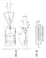
- a method of aligning a radar mount direction according to a comparative example will now be described, by means of taking, as an example, a case where the transmit/receive direction of a radar device 2 mounted on a vehicle 1 is controlled.
- the radar device 2 is mounted on the front of the vehicle 1.
- a transmission section 3 of a radar mount direction alignment device (hereinafter also called simply “alignment device”) is disposed at a position (which is a target used for aligning the mount direction of the radar device 2) spaced distance S 1 (e.g., tens of centimeters to one meter) from the vehicle 1.
- the alignment device has the function of transmitting, toward the radar device 2, a signal which behaves as if having been transmitted from a substance farther from the radar device 2 than a distance S 1 or the function of sending a signal toward the radar device 2 with a predetermined delay time.
- the radar device 2 and the transmission section 3 are situated at a height "h" and aligned with a longitudinal center line Lc of the vehicle 1.
- ⁇ 1 denotes the angle of the transmission section 3 with reference to the center line L 1 of the sensing area of the radar device 2.
- the radar device 2 is equipped with a transmit/receive antenna 4 which rotates within a horizontal plane; and a relative angle sensor 5 for detecting a relative angle with reference to a target (i.e., an azimuth angle).
- Information about the angle ⁇ 1 of the transmission section 3 detected by the relative angle sensor 5 is output to the outside from the radar device 2 and is provided on a display device (not shown).
- the transmit/receive direction of the radar device 2 is aligned such that the angle ⁇ 1 assumes a predetermined value (e.g., 0 degree) while the angle ⁇ 1 is detected by the relative angle sensor 5.
- a predetermined value e.g., 0 degree
- the transmission section 3 is provided on the longitudinal center line Lc of the vehicle 1 and in the position spaced distance S 1 from the vehicle 1.
- the transmit/receive direction of the radar device 2 is aligned such that the angle ⁇ 1 of the transmission section 3 with reference to the radar device 2 detected by the relative angle sensor 5 becomes a predetermined angle.
- the mount direction can be aligned accurately.
- An ordinary radar device for example, a radar device of FM-CW mode, involves noise components stemming from the radar itself, or limitations are imposed on the resolving power of a measurement section of the radar. In relation to a radar device of pulse mode, limitations are imposed on pulse width. Hence, the pulse-mode radar encounters difficulty in measuring a target disposed at short range.
- the alignment device has the function of sending, toward the radar device 2, a signal which behaves as if having been received at and transmitted from an object farther from the radar device 2 than distance S 1 , or the function of sending a signal toward the radar device 2 with a predetermined period of delay time. Hence, an attempt can be made to reduce the space required for alignment.
- an adjustment device having the function of sending, toward the radar device 2, a signal which behaves as if having been received at and transmitted from an object disposed at a position farther from the radar device 2 than a distance of S 1 , or the function of sending a signal toward the radar device 2 with a predetermined period of delay time.
- Figs. 2A and 2B show radar mount direction alignment devices 11 and 21.
- the radar mount direction device 11 comprises an antenna 12 for receiving a signal transmitted from the radar device 2; a transmission line 13 for transmitting a signal; an antenna 14 for transmitting, to the radar device 2, the signal that has been transmitted over the transmission line 13; and directional couplers 15, 16.
- a signal is transmitted from the antenna 14 toward the radar device 2, wherein the signal behaves as if having been received at and transmitted from a position spaced distance S 1 from the radar device 2, plus a distance corresponding to half the distance equivalent to a time delay determined by the length of the transmission line 13.
- the radar mount direction alignment device 21 has a transmit/receive antenna 22; a transmission line 23 for transmitting a signal; and a reflector 24 connected to the transmission line 23.
- a transmit/receive antenna 22 When the signal emitted from the radar device 2 is received by the antenna 22, a signal is transmitted from the antenna 22 toward the radar device 2, wherein the signal behaves as if having been received at and transmitted from a position spaced distance S 1 from the radar device 2, plus a distance corresponding to a time delay determined by the length of the transmission line 13.
- the antenna 12 is provided at the entrance of the transmission line 13, and the antenna 14 is provided at the exit of the same. Further, the antenna 22 is provided at the entrance/exit of the transmission line 23. Alternatively, another member for improving the transmit/receive sensitivity, such as a lens, may be provided in lieu of the antenna.
- the transmission lines 13 and 23 include a waveguide, a dielectric line, and an optical fiber. As shown in Figs. 3A and 3B, there may also be employed a radar mount direction alignment device 11A having an amplifier 17 provided in the transmission line 13, or a radar mount direction alignment device 21A having an amplifier 25 provided in the transmission line 23. Use of these devices enable recovery of a signal level which will drop in the course of the signal passing through the transmission line 13 or 23.
- Fig. 4 shows a side view showing a radar mount direction alignment system 300 according to an embodiment the present invention.
- the radar mount direction alignment system 300 includes a radar 302, a controller 301 for controlling the radar 302, and two reflection units 310 and 320 each disposed in front of the radar 302. Radar wave absorbers 330 are disposed above and below a line connecting the radar 302 and the reflection units 310 and 320.
- the radar 302 as well as the radar device 2 in Fig. 1A, is mounted on a front center of a vehicle.
- the radar 302 transmits a predetermined signal to scan in the horizontal direction of the vehicle.
- the radar 302 scans so that the signal propagates in the vehicle traveling direction parallel to the horizontal direction.
- the signal reflects on a reflector existing in the scanning direction, and is received by the radar 302.
- the controller 301 analyzes the signal received by the radar 302, and determines misalignment of the radar mount direction based on the scanning direction of the signal, the receiving timing and the intensity of the reflected signal from the reflector.
- the reflection unit 310 includes an antenna 313, a transmission line 314, an attenuator 315 and a reflector 316.
- a signal received from the radar 302 by the antenna 313 is reflected by the reflector 316 through the transmission line 314 and the attenuator 315, propagating in the described order.
- the reflected signal propagates through the attenuator 315 and the transmission line 314, and then is transmitted from the antenna 313 to the radar 302.
- the reflection unit 320 includes an antenna 323, a transmission line 324, an attenuator 325 and a reflector 326.
- a signal received from the radar 302 by the antenna 323 is reflected by the reflector 326 through the transmission line 324 and the attenuator 325, propagating in the described order.
- the reflected signal propagates through the attenuator 325 and the transmission line 324, and then is transmitted from the antenna 323 to the radar 302.
- Fig. 5 shows the antennas 313 and 323 as seen from the radar 302 in the signal transmitting direction.
- the antennas 313 and 323 are disposed above and below to have a predetermined space x from the horizontal surface of the signal propagating direction from the radar 302.
- the distances between the radar 302 and the antennas 313 and 323 are the same, and about 1-10m.
- the transmission lines 314 and 324 have different lengths L1 and L2 from each other.
- the lengths of L1 and L2 are about 1-10m. In the fifteenth embodiment, for example, L1 is 5m and L2 is 10m.
- the transmission lines 314 and 324 basically have the same characteristics except for the difference of the length.
- the transmission lines 314 and 324 are made of the same material.
- each of the received signals by the antennas 313 and 314 is attenuated in intensity by a predetermined ratio in accordance with each length L1 or L2.
- the distance x, and the lengths L1 and L2 of the transmission lines 313 and 314 are not limited in the specific values as described above. These values may be set in accordance with the types of radar, or the range or time discrimination ability of the radar 302.
- a transmission line connecting the attenuator 315 with the reflector 316 is the same in the amount of attenuation as a transmission line connecting the attenuator 325 with the reflector 326.
- the attenuators 315 and 325 attenuate the signals transmitted through the transmission lines 314 and 324, by predetermined ratios, respectively.
- the amounts of attenuation by the transmission lines 314 and 324 are set so that the signals outputted from the antennas 313 and 323 to the radar 302 are the same in intensity.
- the amount of attenuation of the signal in the reflection unit 310 is different from the amount of attenuation of the signal in the reflection unit 320 due to the difference between the length L1 (5m) of the transmission line 314 and the length L2 (10m) of the transmission line 324.
- the attenuators 315 and 325 are provided to attenuate each of the signals to compensate for the difference therebetween.
- the attenuators 315 and 325 attenuate the signals so that the input-signal/output-signal intensity ratio of the antenna 313 is the same as the input-signal/output-signal intensity ratio of the antenna 323.
- the attenuation ratio of the reflection unit 310 is the same as that of the reflection unit 320.
- the radio wave absorbers 330 prevent the signal from the radar 302 from being reflected by any members except for the reflection units 310 and 320 and transmitting toward the radar 302. If necessary, additional radio wave absorbers may be provided except for the positions as shown in Fig. 4.
- the scanned signal from the radar 302 directed to the antennas 313 and 323 in the horizontal direction are received by the antennas 313 and 323. Since the distance from the radar 302 to the antenna 313 is the same as that of from the radar 302 to the antenna 323, the received intensities of the signals received by antennas 313 and 323 are the same if the alignment of the radar 302 is proper.
- the signal received by the antenna 313 is transmitted through the transmission line 314 and the attenuator 315, reflected by the reflector 316, and then outputted from the antenna 313 through the transmission line 314 and the attenuator 315.
- the signal received by the antenna 323 is transmitted through the transmission line 324 and the attenuator 325, reflected by the reflector 326, and then outputted from the antenna 323 through the transmission line 324 and the attenuator 325.
- the radar 302 receives the output signals with a timing delay depending on the lengths L1 and L2 of the transmission lines 314 and 315.
- the intensities of the output signals from the reflection units 310 and 320 are the same. Accordingly, the intensities of the received signals from the reflection units 310 and 320 by the radar 302 are the same.
- the alignment of the radar 302 is out of order and the transmitting direction of the signal from the radar 302 is shifted upwardly or downwardly, a difference is generated between the intensities of the signals received by the antenna 313 and antenna 323. Since the reflection units 310 and 320 attenuates the signals by the same ratio, and transmits the attenuated signals toward the radar 302. Accordingly, if the alignment is out of order, the output signals from the antennas 313 and 323 toward the radar 302 are different in intensity, and then the received signals from the reflection units 310 and 320 are also different in intensity.
- Fig. 6 shows a relation between the alignment disorder and intensity difference between the signals received from the reflection units 310 and 320.
- the intensity difference is defined by subtracting the intensity of the output signal from the reflection units 320 from the intensity of the output signal from the reflection units 310.
- the signal intensity of the antenna 313 is stronger than that of the antenna 323. This means that the signal transmitting direction of the radar 302 is shifted upwardly.
- the intensity difference is in the (-)-region, the signal intensity of the antenna 323 is stronger than that of the antenna 313. This means that the signal transmitting direction of the radar 302 is shifted downwardly.
- the mount direction of the radar 302 is adjusted in order to null the intensity difference.
- the alignment of the radar mount direction is properly adjusted in the vertical direction.
- the antennas are positioned above and below with the same distance apart from the radar. Since the transmission lengths in the transmission lines are different in both reflection units, the radar can discriminately receive the each of the output signals from the reflection units. If the ideal distances L1 and L2 of the transmission lines are the same, the radar cannot distinguish the received signals from both reflection units from each other. Namely, if the distances L1 and L2 are the same, the radar cannot determine the received signal having the larger intensity to be transmitted from either of the reflection units even if the radar is disposed in disorder. However, the distances are different, the radar can distinguish the signals from each other since the radar has a function of measuring a distance from the reflection unit and a receiving level that depends on the distance from the reflection unit. To utilize the characteristics, a user can adjust the alignment of the radar mount direction in the vertical direction.
- the attenuator may be provided in either of the reflection units, because the length of the transmission line is different and the attenuation ratio of the reflection unit is the same in both of the reflection units.
Landscapes
- Engineering & Computer Science (AREA)
- Radar, Positioning & Navigation (AREA)
- Remote Sensing (AREA)
- Physics & Mathematics (AREA)
- Computer Networks & Wireless Communication (AREA)
- General Physics & Mathematics (AREA)
- Electromagnetism (AREA)
- Radar Systems Or Details Thereof (AREA)
Claims (6)
- Dispositif d'alignement d'un support de radar destiné à un radar (302) monté sur un véhicule et émettant un signal, le dispositif d'alignement du support de radar comprenant :une première unité de réflexion comportant :dans lequel la longueur de la première ligne de transmission (314) est différente de celle de la seconde ligne de transmission (324) ; etune première antenne (313) permettant de recevoir le signal émis par le radar et de transmettre le signal en direction du radar ;une première ligne de transmission (314) permettant de transmettre le signal reçu par la première antenne (313) ;un premier atténuateur (315) permettant d'atténuer le signal provenant de la première ligne de transmission (314) suivant un premier rapport prédéterminé ; etun premier réflecteur (316) permettant de réfléchir le signal provenant du premier atténuateur ; etune seconde unité de réflexion comportant :une seconde antenne (323) permettant de recevoir le signal émis par le radar et de transmettre le signal en direction du radar ;une seconde ligne de transmission (324) permettant de transmettre le signal reçu par la seconde antenne ;un second atténuateur (325) permettant d'atténuer le signal provenant de la seconde ligne de transmission suivant un second rapport prédéterminé ; etun second réflecteur (326) permettant de réfléchir le signal provenant du second atténuateur,
dans lequel le premier rapport prédéterminé et le second rapport prédéterminé sont tels que lorsque la première antenne (313) et la seconde antenne (323) reçoivent des signaux de la même intensité, une intensité du signal de sortie provenant de la première unité de réflexion est égale à une intensité du signal de sortie provenant de la seconde unité de réflexion. - Dispositif d'alignement d'un support de radar selon la revendication 1, dans lequel le signal réfléchi par le premier réflecteur (316) est transmis via le premier atténuateur (715) et la première ligne de transmission (314) à la première antenne (313) et émis en direction du radar ; et
le signal réfléchi par le second réflecteur (326) est transmis via le second atténuateur (325) et la seconde ligne de transmission (324) à la seconde antenne (323) et émis en direction du radar. - Dispositif d'alignement d'un support de radar selon la revendication 1, dans lequel la première valeur prédéterminée du premier atténuateur (315) et la seconde valeur prédéterminée du second atténuateur (325) sont déterminées en fonction de la longueur de la première ligne de transmission (314) et de la longueur de la seconde ligne de transmission (324).
- Dispositif d'alignement d'un support de radar selon la revendication 1, dans lequel la première antenne (313) de la première unité de réflexion et la seconde antenne (323) de la seconde unité de réflexion se trouvent à la même distance d'une surface horizontale comprenant la direction de balayage du radar.
- Dispositif d'alignement d'un support de radar selon la revendication 1, dans lequel la première antenne (313) de la première unité de réflexion et la seconde antenne (323) de la seconde unité de réflexion se trouvent à la même distance du radar.
- Dispositif d'alignement d'un support de radar selon la revendication 2, dans lequel la direction de montage du radar est réglée en fonction des signaux provenant de la première unité de réflexion et de la seconde unité de réflexion.
Applications Claiming Priority (6)
| Application Number | Priority Date | Filing Date | Title |
|---|---|---|---|
| JP2001032996A JP3500360B2 (ja) | 2001-02-08 | 2001-02-08 | レーダ取付方向調整装置、及びレーダ取付方向調整方法 |
| JP2001032996 | 2001-02-08 | ||
| JP2001034406A JP2002243837A (ja) | 2001-02-09 | 2001-02-09 | レーダ取付方向調整方法、及びレーダ装置 |
| JP2001034406 | 2001-02-09 | ||
| JP2001034725 | 2001-02-09 | ||
| JP2001034725A JP2002243838A (ja) | 2001-02-09 | 2001-02-09 | レーダ取付方向調整方法、及びレーダ取付方向調整装置 |
Publications (3)
| Publication Number | Publication Date |
|---|---|
| EP1231480A2 EP1231480A2 (fr) | 2002-08-14 |
| EP1231480A3 EP1231480A3 (fr) | 2003-08-06 |
| EP1231480B1 true EP1231480B1 (fr) | 2006-06-21 |
Family
ID=27345944
Family Applications (1)
| Application Number | Title | Priority Date | Filing Date |
|---|---|---|---|
| EP02250856A Expired - Lifetime EP1231480B1 (fr) | 2001-02-08 | 2002-02-07 | Procédé et dispositif de l'alignement d'un support de radar, et radar aligné par ce procédé ou ce dispositif |
Country Status (5)
| Country | Link |
|---|---|
| US (1) | US6933883B2 (fr) |
| EP (1) | EP1231480B1 (fr) |
| KR (1) | KR100489226B1 (fr) |
| CN (1) | CN1293390C (fr) |
| DE (1) | DE60212468T2 (fr) |
Families Citing this family (58)
| Publication number | Priority date | Publication date | Assignee | Title |
|---|---|---|---|---|
| JP4740449B2 (ja) * | 2000-12-27 | 2011-08-03 | 富士通テン株式会社 | 車載用レーダの上下軸ずれ検出装置 |
| DE10229334B4 (de) * | 2002-06-29 | 2010-09-23 | Robert Bosch Gmbh | Verfahren und Vorrichtung zur Kalibrierung von Sensoren im Kraftfahrzeug mittels eines Kalibrierobjekts mit Triple-Spiegel als Bezugsmerkmal |
| US7136753B2 (en) * | 2002-12-05 | 2006-11-14 | Denso Corporation | Object recognition apparatus for vehicle, inter-vehicle control apparatus, and distance measurement apparatus |
| US7162200B2 (en) * | 2003-04-15 | 2007-01-09 | Chung Shan Institute Of Science And Technology | Antenna calibration system and method |
| US6731236B1 (en) * | 2003-06-11 | 2004-05-04 | Honeywell International Inc. | Methods and apparatus for optimizing interferometric radar altimeter cross track accuracy |
| JP4232570B2 (ja) * | 2003-07-31 | 2009-03-04 | 株式会社デンソー | 車両用レーダ装置 |
| US7382913B2 (en) | 2003-08-22 | 2008-06-03 | Hunter Engineering Company | Method and apparatus for guiding placement of vehicle service fixtures |
| JP2006184130A (ja) * | 2004-12-27 | 2006-07-13 | Tdk Corp | レーダー装置 |
| JP4109679B2 (ja) * | 2005-02-07 | 2008-07-02 | 三菱電機株式会社 | 車載用レーダの電波軸調整装置 |
| US7253722B2 (en) * | 2005-06-09 | 2007-08-07 | Delphi Technologies, Inc. | Sensor alignment detection method for an infrared blind-zone sensing system |
| JP4444265B2 (ja) * | 2006-11-27 | 2010-03-31 | 富士通テン株式会社 | 車両用レーダ装置およびその製造方法、基準部並びにビームの出射する方向の調整方法 |
| US7884772B2 (en) * | 2007-05-07 | 2011-02-08 | Lockheed Martin Corporation | Radar apparatus and alignment sensor |
| EP2026094B1 (fr) * | 2007-08-10 | 2010-09-29 | Siemens Milltronics Process Instruments Inc. | Système d'étalonnage de radar pour temps de vol |
| DE102007041511B4 (de) | 2007-08-31 | 2025-03-20 | HELLA GmbH & Co. KGaA | Vorrichtung zum Justieren und Prüfen eines Radarsensors |
| DE102008054579B4 (de) | 2008-12-12 | 2022-10-13 | Robert Bosch Gmbh | Dejustageerkennung für einen Radarsensor |
| US8344940B2 (en) * | 2009-01-22 | 2013-01-01 | Mando Corporation | Apparatus and sensor for adjusting sensor vertical alignment |
| KR101053855B1 (ko) * | 2009-01-22 | 2011-08-03 | 주식회사 만도 | 센서 수직 얼라이먼트 조절 장치 및 센서 |
| JP4790045B2 (ja) * | 2009-05-19 | 2011-10-12 | 本田技研工業株式会社 | レーダの軸ずれを判定する装置 |
| CN101702018B (zh) * | 2009-11-12 | 2012-01-04 | 中国电子科技集团公司第四十一研究所 | 一种大调制带宽线性调频信号频响校准方法 |
| DE102010020022A1 (de) * | 2010-05-10 | 2011-11-10 | Valeo Schalter Und Sensoren Gmbh | Fahrerassistenzeinrichtung für ein Fahrzeug, Fahrzeug und Verfahren zum Betreiben eines Radargeräts |
| KR100979943B1 (ko) * | 2010-05-26 | 2010-09-06 | 삼성탈레스 주식회사 | 차량용 레이더 안테나의 각도를 조절하는 장치 및 방법 |
| JP5697904B2 (ja) * | 2010-06-16 | 2015-04-08 | 株式会社豊田中央研究所 | レーダ装置及び検知方法 |
| EP2663971A1 (fr) | 2010-11-15 | 2013-11-20 | Image Sensing Systems, Inc. | Système de détection de la circulation hybride et procédé associé |
| US9472097B2 (en) | 2010-11-15 | 2016-10-18 | Image Sensing Systems, Inc. | Roadway sensing systems |
| DE102011079522A1 (de) * | 2011-07-21 | 2013-01-24 | Robert Bosch Gmbh | Erkennung einer dejustage eines radarsensors eines fahrzeugs |
| US8692707B2 (en) | 2011-10-06 | 2014-04-08 | Toyota Motor Engineering & Manufacturing North America, Inc. | Calibration method for automotive radar using phased array |
| DE102012201986B4 (de) * | 2012-02-10 | 2024-10-10 | Robert Bosch Gmbh | Radarsensoreinrichtung mit Justierspiegel |
| KR101335074B1 (ko) * | 2012-03-02 | 2013-12-03 | 주식회사 만도 | 레이더 장치의 얼라이먼트 시스템 및 얼라이먼트 방법 |
| KR102048361B1 (ko) * | 2013-02-28 | 2019-11-25 | 엘지전자 주식회사 | 거리 검출 장치, 및 이를 구비하는 영상처리장치 |
| WO2014178125A1 (fr) | 2013-04-30 | 2014-11-06 | 古河電気工業株式会社 | Appareil radar |
| DE102013209494A1 (de) * | 2013-05-22 | 2014-11-27 | Robert Bosch Gmbh | Verfahren und Vorrichtung zum Ermitteln einer Dejustage eines Radarsensors eines Fahrzeugs |
| KR102157993B1 (ko) * | 2013-11-28 | 2020-09-21 | 현대모비스 주식회사 | 차량용 레이더 얼라인먼트 방법 및 시스템 |
| WO2015148830A1 (fr) * | 2014-03-28 | 2015-10-01 | Hunter Engineering Company | Appareil d'étalonnage pour capteurs télémétriques sur un véhicule |
| US10585170B2 (en) * | 2014-08-15 | 2020-03-10 | Robert Bosch Gbmh | Automotive radar alignment |
| US10890648B2 (en) * | 2014-10-24 | 2021-01-12 | Texas Instruments Incorporated | Method and apparatus for generating alignment matrix for camera-radar system |
| US9568592B1 (en) * | 2014-11-04 | 2017-02-14 | Google Inc. | Automotive sensor alignment with external IMU tool |
| CN105738871A (zh) * | 2014-12-24 | 2016-07-06 | 松下知识产权经营株式会社 | 雷达系统 |
| US20160223649A1 (en) * | 2015-01-30 | 2016-08-04 | Robert Bosch Gmbh | Systems and methods for radar vertical misalignment detection |
| US9784829B2 (en) * | 2015-04-06 | 2017-10-10 | GM Global Technology Operations LLC | Wheel detection and its application in object tracking and sensor registration |
| CN104808185B (zh) * | 2015-05-04 | 2018-02-09 | 北京敏视达雷达有限公司 | 一种角度误差的检测方法及装置 |
| KR101684551B1 (ko) * | 2015-06-26 | 2016-12-08 | 현대자동차 주식회사 | Bsd센서의 장착각 감지 시스템 및 감지방법 |
| US10527714B2 (en) * | 2016-11-17 | 2020-01-07 | Rohde & Schwarz Gmbh & Co. Kg | Calibration device and calibration method for calibrating antenna arrays |
| CN108614239A (zh) * | 2016-12-12 | 2018-10-02 | 北京行易道科技有限公司 | 对准系统 |
| DE102017123435A1 (de) | 2017-10-09 | 2019-04-11 | Krohne Messtechnik Gmbh | Vorrichtung für die Kalibration eines Radar-Entfernungsmessgeräts und Verfahren zum Kalibrieren eines Radar-Entfernungsmessgeräts |
| DE102018203941A1 (de) * | 2018-03-15 | 2019-09-19 | Robert Bosch Gmbh | Automatisches Kalibrieren eines Fahrzeug-Radarsensors |
| US10830872B2 (en) * | 2018-06-07 | 2020-11-10 | Fca Us Llc | Vehicle multi-radar relative phase interferometry alignment systems and methods |
| KR102506943B1 (ko) | 2018-06-25 | 2023-03-07 | 현대자동차 주식회사 | 차량 레이더 검사 시스템 및 그 방법 |
| EP3588135B1 (fr) * | 2018-06-28 | 2021-05-05 | Aptiv Technologies Limited | Procédé de détermination d'une erreur d'alignement d'une antenne et véhicule équipé d'une antenne et d'un dispositif de détection |
| JP7096114B2 (ja) * | 2018-09-25 | 2022-07-05 | 本田技研工業株式会社 | センサ軸調整装置及びセンサ軸調整方法 |
| WO2020080569A1 (fr) * | 2018-10-18 | 2020-04-23 | 인지니어스 주식회사 | Dispositif de détermination de somnolence de conducteur utilisant un signal radar et procédé de fonctionnement associé |
| US11313946B2 (en) * | 2018-11-12 | 2022-04-26 | Hunter Engineering Company | Method and apparatus for identification of calibration targets during vehicle radar system service procedures |
| CN109367529B (zh) * | 2018-11-30 | 2024-03-26 | 南京天安汽车电子科技股份有限公司 | 毫米波雷达组合安装结构及虚拟隧道构建与障碍判断方法 |
| CN109738905B (zh) * | 2018-12-28 | 2021-03-23 | 百度在线网络技术(北京)有限公司 | 超声波传感器安装位的确定方法、装置及设备 |
| US11069982B2 (en) * | 2019-01-02 | 2021-07-20 | Honda Motor Co., Ltd. | Anechoic chamber and method of calibrating a radar system |
| CN111064477B (zh) * | 2019-12-31 | 2020-08-04 | 郑州科技学院 | 角度可调的电力通信信号发射装置 |
| JP7316468B2 (ja) * | 2020-04-28 | 2023-07-27 | ヴィオニア スウェーデン エービー | レーダトランシーバ試験 |
| US20240427008A1 (en) * | 2023-06-23 | 2024-12-26 | Teradar, Inc. | Techniques for adaptive collection of information about target objects based on situational awareness data |
| US20250199120A1 (en) * | 2023-12-19 | 2025-06-19 | Rohde & Schwarz Gmbh & Co. Kg | Vehicle sensor testing with field of view enhancement |
Family Cites Families (45)
| Publication number | Priority date | Publication date | Assignee | Title |
|---|---|---|---|---|
| US2505525A (en) * | 1944-07-26 | 1950-04-25 | Philco Corp | Device for testing pulse type radar system |
| US2841785A (en) * | 1946-05-08 | 1958-07-01 | Jr Frederic Cunningham | Target simulating signal generator |
| US2802207A (en) * | 1949-06-21 | 1957-08-06 | Jr Henry S Sommers | Method of adjusting radar tracking apparatus |
| GB691570A (en) | 1951-03-22 | 1953-05-13 | Vickers Electrical Co Ltd | Improvements relating to radar testing equipment |
| US2922157A (en) * | 1954-03-30 | 1960-01-19 | Pitometer Log Corp | Radar signal simulator |
| US2781511A (en) * | 1955-01-13 | 1957-02-12 | Jr Charles B Pear | Echo simulator |
| US2825058A (en) * | 1955-02-04 | 1958-02-25 | Earl H Rix | Target simulator for radar system checking |
| US2942257A (en) * | 1955-12-12 | 1960-06-21 | Gen Mills Inc | Radar tester |
| CH355485A (de) | 1955-12-12 | 1961-07-15 | Gen Mills Inc | Radar-Prüfeinrichtung |
| US3018478A (en) * | 1957-08-05 | 1962-01-23 | Westinghouse Electric Corp | Pulse doppler moving target simulator |
| US2952848A (en) * | 1958-12-24 | 1960-09-13 | Aircraft Armaments Inc | Method and means for testing the calibration of radar systems |
| US3162854A (en) * | 1961-05-08 | 1964-12-22 | Robert R Campbell | Target simulator for pulse doppler radar |
| BE636918A (fr) * | 1962-09-04 | |||
| GB1085071A (en) | 1963-11-15 | 1967-09-27 | Elliott Brothers London Ltd | Radar target simulators |
| US3329953A (en) * | 1966-06-15 | 1967-07-04 | Sierra Research Corp | Doppler target simulator |
| GB2035744B (en) * | 1978-11-22 | 1983-05-05 | Marconi Co Ltd | Apparatus for detecting moving targets or other objects of interest |
| FR2569857B1 (fr) * | 1982-10-13 | 1988-05-13 | Trt Telecom Radio Electr | Simulateur de retard variable electriquement pour appareil de mesure de distance a onde continue modulee en frequence |
| FR2573217B1 (fr) * | 1984-11-13 | 1987-01-23 | Trt Telecom Radio Electr | Simulateur de retards pour appareil de mesure de distance a onde continue modulee en frequence |
| US4683473A (en) * | 1986-01-10 | 1987-07-28 | Honeywell Inc. | Radar transit time simulator device |
| US4737792A (en) * | 1986-06-20 | 1988-04-12 | Westinghouse Electric Corp. | Counter-based simulated target generator |
| US5262787A (en) * | 1987-03-06 | 1993-11-16 | Raytheon Company | Recirculating delay line radar performance monitor |
| IL102119A (en) * | 1991-06-05 | 1995-11-27 | Commw Of Australia | Environmental radar generator |
| US5164734A (en) * | 1991-10-07 | 1992-11-17 | Duane G. Fredericks | Radar target with delayed reply means |
| US5177488A (en) * | 1991-10-08 | 1993-01-05 | Hughes Aircraft Company | Programmable fiber optic delay line, and radar target simulation system incorporating the same |
| US5223840A (en) * | 1992-03-13 | 1993-06-29 | The United States Of America As Represented By The Secretary Of The Navy | Low cost radar target simulator for remote radar testing |
| JPH0647884U (ja) | 1992-12-09 | 1994-06-28 | 横河電子機器株式会社 | 疑似反射体 |
| US5518400A (en) * | 1994-11-15 | 1996-05-21 | Hughes Aircraft Company | Portable radar target simulator |
| JP3157091B2 (ja) | 1995-05-30 | 2001-04-16 | 富士通テン株式会社 | ビームの光軸調整装置 |
| JP3114849B2 (ja) | 1995-12-25 | 2000-12-04 | 本田技研工業株式会社 | 車両用障害物検知装置の検知範囲調整機構 |
| JPH09311186A (ja) | 1996-05-23 | 1997-12-02 | Honda Access Corp | レーダ装置 |
| JPH09318731A (ja) | 1996-05-24 | 1997-12-12 | Toyo Commun Equip Co Ltd | 高周波信号可変遅延回路 |
| GB2318010A (en) | 1996-10-07 | 1998-04-08 | Secr Defence | Reflecting transponder for calibrating phased-array radar |
| DE19707591C1 (de) | 1997-02-26 | 1998-10-29 | Bosch Gmbh Robert | Verfahren und Vorrichtung zur Überprüfung der Ausrichtung einer Strahlcharakteristik eines Objektsensors |
| DE19707590C2 (de) | 1997-02-26 | 2000-12-14 | Bosch Gmbh Robert | Verfahren und Vorrichtung zur Justierung der Ausrichtung einer Strahlcharakteristik eines Entfernungssensors |
| US5920281A (en) * | 1997-08-05 | 1999-07-06 | Wiltron Company | Radar test system for collision avoidance automotive radar |
| FR2769085B1 (fr) | 1997-09-26 | 1999-12-03 | Thomson Csf | Dispositif de reglage de l'alignement d'un radar pour automobiles |
| JP3462740B2 (ja) | 1998-01-06 | 2003-11-05 | 株式会社日立製作所 | 車載レーダの軸調整方法 |
| JP3057157B2 (ja) * | 1998-02-19 | 2000-06-26 | 本田技研工業株式会社 | 移動体用物体検知装置 |
| DE19813631A1 (de) | 1998-03-27 | 1999-10-07 | Honeywell Ag | Radar-Entfernungsmesser |
| JP3438768B2 (ja) | 1998-05-19 | 2003-08-18 | トヨタ自動車株式会社 | レーダ装置の位相補正値決定方法 |
| US5977906A (en) * | 1998-09-24 | 1999-11-02 | Eaton Vorad Technologies, L.L.C. | Method and apparatus for calibrating azimuth boresight in a radar system |
| US6087995A (en) * | 1999-02-17 | 2000-07-11 | Anritsu Company | Universal autoradar antenna alignment system |
| JP2001013238A (ja) | 1999-06-30 | 2001-01-19 | Nippon Signal Co Ltd:The | 物体検知装置及びその動作確認装置 |
| FR2798196B1 (fr) * | 1999-09-07 | 2001-11-30 | Thomson Csf | Procede et dispositif pour l'alignement d'un radar automobile |
| JP2001174540A (ja) * | 1999-12-15 | 2001-06-29 | Fujitsu Ten Ltd | 車両用レーダ装置の取付け角度調整方法および取付け角度調整用支援装置 |
-
2002
- 2002-02-07 US US10/067,345 patent/US6933883B2/en not_active Expired - Fee Related
- 2002-02-07 DE DE60212468T patent/DE60212468T2/de not_active Expired - Lifetime
- 2002-02-07 EP EP02250856A patent/EP1231480B1/fr not_active Expired - Lifetime
- 2002-02-08 CN CNB021045348A patent/CN1293390C/zh not_active Expired - Fee Related
- 2002-02-08 KR KR10-2002-0007423A patent/KR100489226B1/ko not_active Expired - Fee Related
Also Published As
| Publication number | Publication date |
|---|---|
| DE60212468D1 (de) | 2006-08-03 |
| EP1231480A3 (fr) | 2003-08-06 |
| CN1372349A (zh) | 2002-10-02 |
| KR20020066390A (ko) | 2002-08-16 |
| DE60212468T2 (de) | 2007-06-14 |
| KR100489226B1 (ko) | 2005-05-17 |
| EP1231480A2 (fr) | 2002-08-14 |
| US20020105456A1 (en) | 2002-08-08 |
| CN1293390C (zh) | 2007-01-03 |
| US6933883B2 (en) | 2005-08-23 |
Similar Documents
| Publication | Publication Date | Title |
|---|---|---|
| EP1231480B1 (fr) | Procédé et dispositif de l'alignement d'un support de radar, et radar aligné par ce procédé ou ce dispositif | |
| US4716298A (en) | System for automatically detecting presence or absence of a preceding vehicle and method therefor | |
| US4786164A (en) | System and method for detecting intervehicle distance of two vehicles moving in the same traffic lane | |
| US4757450A (en) | Method and system for automatically detecting a preceding vehicle | |
| US7486222B2 (en) | Automotive radar device | |
| US6119067A (en) | Object detecting system for conveyance, etc. | |
| EP1416292B1 (fr) | Système radar optique à balayage | |
| CN101788659B (zh) | 调整传感器垂直对准的装置和传感器 | |
| US6225955B1 (en) | Dual-mode, common-aperture antenna system | |
| JP2008275460A (ja) | レーダ装置 | |
| JP4817282B2 (ja) | 電磁信号を送受信するためのセンサ | |
| CN112965044B (zh) | 一种激光雷达 | |
| JP3500360B2 (ja) | レーダ取付方向調整装置、及びレーダ取付方向調整方法 | |
| KR102394452B1 (ko) | 빔 조향 레이더를 이용한 신호대기 차량 검지 시스템 및 그 방법 | |
| JPH10325869A (ja) | 車両用レーダ装置及びこれを用いた自動走行制御システム | |
| JPH08304550A (ja) | レーダ装置 | |
| JPH0792258A (ja) | 車両用レーダ装置 | |
| JPH06168400A (ja) | 自動車用レーダ | |
| JP2007240369A (ja) | 電波軸調整装置および電波軸調整方法 | |
| GB2069208A (en) | Prevention of collisions of or between industrial trucks | |
| JPH0634754A (ja) | レーダ装置 | |
| JPH06148329A (ja) | 車間距離検出装置 | |
| JP3651769B2 (ja) | 航空機検知システム | |
| JP2002243837A (ja) | レーダ取付方向調整方法、及びレーダ装置 | |
| EP0704714A1 (fr) | Senseur de passage à micro-ondes avec un réflecteur spécial |
Legal Events
| Date | Code | Title | Description |
|---|---|---|---|
| PUAI | Public reference made under article 153(3) epc to a published international application that has entered the european phase |
Free format text: ORIGINAL CODE: 0009012 |
|
| AK | Designated contracting states |
Kind code of ref document: A2 Designated state(s): AT BE CH CY DE DK ES FI FR GB GR IE IT LI LU MC NL PT SE TR |
|
| AX | Request for extension of the european patent |
Free format text: AL;LT;LV;MK;RO;SI |
|
| PUAL | Search report despatched |
Free format text: ORIGINAL CODE: 0009013 |
|
| AK | Designated contracting states |
Designated state(s): AT BE CH CY DE DK ES FI FR GB GR IE IT LI LU MC NL PT SE TR |
|
| AX | Request for extension of the european patent |
Extension state: AL LT LV MK RO SI |
|
| 17P | Request for examination filed |
Effective date: 20040128 |
|
| AKX | Designation fees paid |
Designated state(s): AT BE CH LI |
|
| RBV | Designated contracting states (corrected) |
Designated state(s): DE FR GB |
|
| 17Q | First examination report despatched |
Effective date: 20040420 |
|
| REG | Reference to a national code |
Ref country code: DE Ref legal event code: 8566 |
|
| GRAP | Despatch of communication of intention to grant a patent |
Free format text: ORIGINAL CODE: EPIDOSNIGR1 |
|
| GRAS | Grant fee paid |
Free format text: ORIGINAL CODE: EPIDOSNIGR3 |
|
| GRAA | (expected) grant |
Free format text: ORIGINAL CODE: 0009210 |
|
| AK | Designated contracting states |
Kind code of ref document: B1 Designated state(s): DE FR GB |
|
| REG | Reference to a national code |
Ref country code: GB Ref legal event code: FG4D |
|
| REF | Corresponds to: |
Ref document number: 60212468 Country of ref document: DE Date of ref document: 20060803 Kind code of ref document: P |
|
| ET | Fr: translation filed | ||
| PLBE | No opposition filed within time limit |
Free format text: ORIGINAL CODE: 0009261 |
|
| STAA | Information on the status of an ep patent application or granted ep patent |
Free format text: STATUS: NO OPPOSITION FILED WITHIN TIME LIMIT |
|
| 26N | No opposition filed |
Effective date: 20070322 |
|
| REG | Reference to a national code |
Ref country code: FR Ref legal event code: PLFP Year of fee payment: 14 |
|
| PGFP | Annual fee paid to national office [announced via postgrant information from national office to epo] |
Ref country code: DE Payment date: 20150203 Year of fee payment: 14 |
|
| PGFP | Annual fee paid to national office [announced via postgrant information from national office to epo] |
Ref country code: FR Payment date: 20150210 Year of fee payment: 14 Ref country code: GB Payment date: 20150204 Year of fee payment: 14 |
|
| REG | Reference to a national code |
Ref country code: DE Ref legal event code: R119 Ref document number: 60212468 Country of ref document: DE |
|
| GBPC | Gb: european patent ceased through non-payment of renewal fee |
Effective date: 20160207 |
|
| REG | Reference to a national code |
Ref country code: FR Ref legal event code: ST Effective date: 20161028 |
|
| PG25 | Lapsed in a contracting state [announced via postgrant information from national office to epo] |
Ref country code: GB Free format text: LAPSE BECAUSE OF NON-PAYMENT OF DUE FEES Effective date: 20160207 Ref country code: DE Free format text: LAPSE BECAUSE OF NON-PAYMENT OF DUE FEES Effective date: 20160901 Ref country code: FR Free format text: LAPSE BECAUSE OF NON-PAYMENT OF DUE FEES Effective date: 20160229 |