EP1231704A2 - Convertisseur d'énergie - Google Patents
Convertisseur d'énergie Download PDFInfo
- Publication number
- EP1231704A2 EP1231704A2 EP02290258A EP02290258A EP1231704A2 EP 1231704 A2 EP1231704 A2 EP 1231704A2 EP 02290258 A EP02290258 A EP 02290258A EP 02290258 A EP02290258 A EP 02290258A EP 1231704 A2 EP1231704 A2 EP 1231704A2
- Authority
- EP
- European Patent Office
- Prior art keywords
- primary
- circuit
- switching means
- windings
- converter
- Prior art date
- Legal status (The legal status is an assumption and is not a legal conclusion. Google has not performed a legal analysis and makes no representation as to the accuracy of the status listed.)
- Granted
Links
- 238000004804 winding Methods 0.000 claims abstract description 116
- 239000004020 conductor Substances 0.000 claims description 33
- 239000003990 capacitor Substances 0.000 claims description 9
- 230000009977 dual effect Effects 0.000 claims description 7
- 238000000034 method Methods 0.000 claims description 7
- 230000001131 transforming effect Effects 0.000 claims 2
- 230000005669 field effect Effects 0.000 abstract description 2
- 238000006243 chemical reaction Methods 0.000 abstract 1
- 235000021183 entrée Nutrition 0.000 description 9
- 230000002457 bidirectional effect Effects 0.000 description 2
- 238000010586 diagram Methods 0.000 description 2
- 239000003607 modifier Substances 0.000 description 2
- 230000009466 transformation Effects 0.000 description 2
- 230000015556 catabolic process Effects 0.000 description 1
- 210000000056 organ Anatomy 0.000 description 1
- 239000004065 semiconductor Substances 0.000 description 1
- 230000004584 weight gain Effects 0.000 description 1
- 235000019786 weight gain Nutrition 0.000 description 1
Images


Classifications
-
- H—ELECTRICITY
- H02—GENERATION; CONVERSION OR DISTRIBUTION OF ELECTRIC POWER
- H02M—APPARATUS FOR CONVERSION BETWEEN AC AND AC, BETWEEN AC AND DC, OR BETWEEN DC AND DC, AND FOR USE WITH MAINS OR SIMILAR POWER SUPPLY SYSTEMS; CONVERSION OF DC OR AC INPUT POWER INTO SURGE OUTPUT POWER; CONTROL OR REGULATION THEREOF
- H02M3/00—Conversion of DC power input into DC power output
- H02M3/22—Conversion of DC power input into DC power output with intermediate conversion into AC
- H02M3/24—Conversion of DC power input into DC power output with intermediate conversion into AC by static converters
- H02M3/28—Conversion of DC power input into DC power output with intermediate conversion into AC by static converters using discharge tubes with control electrode or semiconductor devices with control electrode to produce the intermediate AC
- H02M3/325—Conversion of DC power input into DC power output with intermediate conversion into AC by static converters using discharge tubes with control electrode or semiconductor devices with control electrode to produce the intermediate AC using devices of a triode or a transistor type requiring continuous application of a control signal
- H02M3/335—Conversion of DC power input into DC power output with intermediate conversion into AC by static converters using discharge tubes with control electrode or semiconductor devices with control electrode to produce the intermediate AC using devices of a triode or a transistor type requiring continuous application of a control signal using semiconductor devices only
- H02M3/33569—Conversion of DC power input into DC power output with intermediate conversion into AC by static converters using discharge tubes with control electrode or semiconductor devices with control electrode to produce the intermediate AC using devices of a triode or a transistor type requiring continuous application of a control signal using semiconductor devices only having several active switching elements
- H02M3/33573—Full-bridge at primary side of an isolation transformer
-
- H—ELECTRICITY
- H02—GENERATION; CONVERSION OR DISTRIBUTION OF ELECTRIC POWER
- H02M—APPARATUS FOR CONVERSION BETWEEN AC AND AC, BETWEEN AC AND DC, OR BETWEEN DC AND DC, AND FOR USE WITH MAINS OR SIMILAR POWER SUPPLY SYSTEMS; CONVERSION OF DC OR AC INPUT POWER INTO SURGE OUTPUT POWER; CONTROL OR REGULATION THEREOF
- H02M1/00—Details of apparatus for conversion
- H02M1/0067—Converter structures employing plural converter units, other than for parallel operation of the units on a single load
- H02M1/0077—Plural converter units whose outputs are connected in series
-
- H—ELECTRICITY
- H02—GENERATION; CONVERSION OR DISTRIBUTION OF ELECTRIC POWER
- H02M—APPARATUS FOR CONVERSION BETWEEN AC AND AC, BETWEEN AC AND DC, OR BETWEEN DC AND DC, AND FOR USE WITH MAINS OR SIMILAR POWER SUPPLY SYSTEMS; CONVERSION OF DC OR AC INPUT POWER INTO SURGE OUTPUT POWER; CONTROL OR REGULATION THEREOF
- H02M3/00—Conversion of DC power input into DC power output
- H02M3/22—Conversion of DC power input into DC power output with intermediate conversion into AC
- H02M3/24—Conversion of DC power input into DC power output with intermediate conversion into AC by static converters
- H02M3/28—Conversion of DC power input into DC power output with intermediate conversion into AC by static converters using discharge tubes with control electrode or semiconductor devices with control electrode to produce the intermediate AC
- H02M3/285—Single converters with a plurality of output stages connected in parallel
Definitions
- the invention relates to an electrical energy converter combining series and / or in parallel a plurality of transformers.
- documents US 4,339,704 and US 3,419,786 describe a converter comprising a primary winding and several secondary windings.
- the converter is supplied by an alternating voltage.
- the windings secondary are connected in parallel on two conductors, each conductor having diodes connected in series. So the two conductors are interconnected, between their respective diodes, by a secondary winding.
- the converter described in document US Pat. No. 3,419,786 comprises, on each conductor, N + 1 diodes for N secondary windings. It includes elsewhere N switches connected in series with each winding secondary.
- the converter described in document US Pat. No. 4,339,704 includes, on each conductor, N + 2 diodes connected in series, two diodes being arranged between the connections of successive secondary windings.
- N-1 switches connect the two conductors between two diodes connected successively in series.
- the invention aims to solve these problems by presenting a converter simple implementation requiring a reduced number of switches while allowing to obtain a range of voltage variation at equal output or superior, and tolerating simple breakdowns.
- the converter according to the invention can operate with a voltage continuous or alternative input or output.
- each primary circuit or secondary converter includes a set of means of switching connected to the N primary windings and to the N windings secondary, and in that it comprises means for controlling means switching of at least one of the primary or secondary circuits, the means of switching being connected so that we can associate the N primary or secondary windings in series and / or parallel using the control means.
- the primary circuit comprises a generator of current that feeds the input terminals and the secondary circuit includes a voltage generator connected in parallel to the output terminals.
- the primary circuit comprises a generator voltage connected in parallel on the input terminals and the secondary circuit includes a current generator connected to the output terminals.
- Another object of the invention is a method for controlling a converter according to the invention, in which the primary circuit has the first configuration.
- This method includes the steps of moving a pattern of switching successively along the pairs of switching means of the primary circuit and, for each pair of switching means, to reverse possibly the state of one of the switching means of the pair or successively the state of the two switching means of the pair.
- a pair of switching means then corresponds to two means of switching connected before or after the same winding.
- Each primary 1 and secondary 4 circuit includes at least 2N + 2 switching means I N and I ' N.
- the converter also comprises control means 7 for the switching means I N and the N of at least one of the primary or secondary circuits, the switching means being connected so that the N primary or secondary windings can be associated. in series and / or parallel using the control means.
- the control means 7 can control either only the means switching circuit of primary circuit 1 or secondary circuit 4, either order both the primary 1 and secondary 4 switching means.
- the switching means I N and l ' N make it possible to open and close the circuit to which they are connected.
- These switching means can be unidirectional switches or bidirectional, such as diodes, IGBTs, thyristors, triacs, field effect transistors, bipolar transistors, contactors, contacts, GTO, IGCT, MOS, or the like.
- the primary circuit 1 comprises a generator of current which feeds the input terminals 2, 3. This is for example a winding.
- the secondary circuit 4 then includes a voltage generator connected in parallel to the output terminals 5, 6. This is for example a capacitor.
- the primary circuit 1 comprises a generator of voltage (for example a capacitor) connected in parallel on the terminals input 2, 3 and the secondary circuit 4 includes a connected current generator at output terminals 5, 6 (for example a winding).
- a generator of voltage for example a capacitor
- the secondary circuit 4 includes a connected current generator at output terminals 5, 6 (for example a winding).
- Primary 1 and secondary 4 circuits can adopt one of two dual configurations described below.
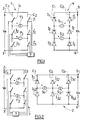
- the first configuration is described with reference to Figure 1, which represents a converter whose two primary 1 and secondary 4 circuits adopt this first configuration.
- the primary 1 and secondary 4 circuits each each comprise two electrical conductors C 1 , C 2 connected in parallel between the input 2, 3 or output 5, 6 terminals.
- Each conductor C 1 , C 2 comprises N + 1 switches in series I N and L ' N respectively.
- the two conductors C 1 , C 2 of the primary circuit are interconnected, between their respective switches I N and I ' N , by a primary winding P N.
- the primary windings P N are connected in parallel between the two conductors C 1 , C 2 .
- the two conductors C 1 , C 2 of the secondary circuit are connected together, between their respective switches I N and I ' N , by a secondary winding S N , so that the secondary windings S N are connected in parallel between the two conductors C 1 , C 2 .
- the switches I N and N of the secondary circuit are diodes. These diodes are all connected in the same direction.
- the windings P 2 , S 2 are in the same direction, while the windings P 1 and S 1 are in opposite directions to each other.
- This configuration makes it possible to obtain a parallel connection of the windings of the secondary circuit when the windings of the primary circuit are in series, and vice versa.
- FIG. 2 represents a converter whose primary circuit 1 presents the first configuration, and the secondary circuit 4 adopts this second configuration.
- the primary circuit 1 is identical to that of FIG. 1.
- the secondary circuit 4 comprises N + 1 electrical conductors C N connected in parallel to the output terminals 5, 6 of the secondary circuit.
- Each conductor C N of the secondary circuit comprises two switches I N, 1 and l N, 2 in series, the conductors C N being linked together in pairs between their respective switches by a secondary winding S N.
- the switches I N, 1 and I N, 2 of the secondary circuit are diodes.
- the configurations of the primary 1 and secondary 4 circuits being dual one of the other, it is not necessary to reverse the direction of a winding on two to obtain a parallel connection of the circuit windings secondary when the windings of the primary circuit are in series, and vice versa.
- Figure 3 describes a variant of the embodiment of Figure 2.
- the same references designate the same components.
- the primary circuit 1 adopts the first configuration and the secondary circuit 4 adopts the second configuration.
- the secondary circuit 4 is identical to that described for FIG. 1, the same elements being indicated by the same references.
- the two conductors C 1 , C 2 of the secondary circuit are also connected to a winding 8 in series and to a capacitor 9 in parallel.
- the secondary circuit Due to the presence of a winding 8, the secondary circuit has a power generator.
- the primary circuit 1 is substantially identical to that described for FIG. 1, the same references referring to the same components.
- the two conductors C 1 , C 2 of the primary circuit are connected in parallel with a capacitor 13.
- the capacitor 13 is itself connected in series with a winding 15 and a voltage generator 16. The latter is connected between the input terminals 2, 3.
- the primary circuit Due to the presence of capacity 13, the primary circuit has a voltage generator.
- a third embodiment is described with reference to FIG. 4.
- N the direction of one of the secondary windings, here S 2 , is reversed with respect to the direction of the primary winding corresponding P 2 and other windings P 1 , S 1 .
- Each switch I N, 1 and I N, 2 of the primary circuit 1 is connected in parallel with a diode 17, in order to be able to operate bidirectionally.
- the switches I N, 1 and l N, 2 of the secondary circuit are diodes.
- the primary circuit is supplied by a voltage generator (VE).
- the circuit secondary is connected to a current generator (winding 18).
- the winding 18 is mounted in series with the positive output terminal 5, a capacity 19 is mounted in parallel between the output terminals 5, 6.
- the primary windings P 1 and P 2 being in parallel, the voltage at each winding is equal to Ve.
- This type of mounting has the advantage of being able to be used with a highly variable input voltage (for example from 100 Volts to 1600 Volts) and to regulate the output voltage to a fixed value.
- Vmax the maximum voltage Ve
- V1 and V2 voltages input substantially equal to about 1/3 Vmax and 2/3 Vmax respectively.
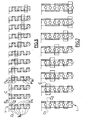
- FIGs 7 and 8 show the conductors C 1 and C 2 of the primary circuit 1. Only the first seven windings P N are shown.
- the sections of conductors C 1 and C 2 in bold lines illustrate switches I N , the closed N and the sections in fine lines of the open switches I N , the N.
- a pair of switching means is defined as being formed of two switching means connected after or before the same winding.
- the switches are made step by step by moving a pattern of switching, symbolized by a frame C, along the pairs of means of switching and possibly reversing the state of one or both of the switching contained in the frame. In the case of two inversions, these are carried out successively.
- control means successively control each pair of switching means I 1 , I ' 1 , then I 2 , I' 2 , ...., I N , l ' N.
- the switching means I N is reversed or not, then the switching means l N is reversed or not.
- This process allows for example to reverse the polarity of the primary circuit, or to reverse the polarity of the voltage across each transformer.
- the example shown in FIG. 6 corresponds to the inversion of the polarity of the primary windings which are in a configuration where all the primary windings P N are in series.
- the reverse polarity is obtained by reversing all the switches.
- the switching means are switched so as to pass from a configuration where all the switching means I N , l ' N are in series, to a configuration where the switching means are in parallel two by two.
- the filters at the input and output of the circuit will be less stressed than in a classic circuit with a large pulsed current.
- the converter according to the invention has the advantage of being tolerant to a single fault: whatever the fault mode of a switch, a transformer, it is possible to operate in degraded mode.
- a primary circuit adopting the first configuration is good suitable for high voltages, because the switches share the voltage between them.
- a secondary circuit adopting the second configuration is well suited for high output currents, because the switches share the current exit.
- the electronic circuit according to the invention has a wide field of application in electronics.
- the invention is not limited to the embodiments described, and in particular to the value of N used.
- the latter can be very variable.
- All or part of the elements of the electronic circuit can also be controlled by computer to obtain the desired association of transformers.
- this last replaces the energy converter arranged in a vehicle railway, supplied indifferently by a direct voltage of 1500V or 3000V or an alternating voltage of 1000V or 1500V, said converter being able to transform this voltage into a voltage suitable for supplying organs electrics embedded in this vehicle.
- the UIC 550 standard International Union Railways
- a heavy and bulky inlet filter consisting of a condenser and an inductor.
- the input generator then becomes a current generator.
- the switch control process regulates a constant current compatible with UIC 550 standard, creating high input impedance.
- the current setpoint is adapted to adjust the voltage Release.
- Another application of the converter is its use as converter responsible for ensuring the traction function of a rail vehicle, powered by an alternating voltage of 15,000V or 25,000V, said converter being able to transform this voltage into a voltage suitable for supplying electrical components on board this vehicle.
- Said electrical converter is therefore devoid of low frequency transformer (50Hz or 16.7Hz) high input voltage.
Landscapes
- Engineering & Computer Science (AREA)
- Power Engineering (AREA)
- Dc-Dc Converters (AREA)
- Inorganic Insulating Materials (AREA)
- Ac-Ac Conversion (AREA)
- Rectifiers (AREA)
- Particle Formation And Scattering Control In Inkjet Printers (AREA)
- Diaphragms For Electromechanical Transducers (AREA)
Abstract
Description
- N transformateurs comprenant chacun un enroulement primaire et un enroulement secondaire,
- un circuit primaire relié à deux bornes d'entrée, sur lequel sont connectés les enroulements primaires des transformateurs,
- un circuit secondaire relié à deux bornes de sortie, sur lequel sont connectés les enroulements secondaires des transformateurs.
- la première configuration comprend deux conducteurs électriques connectés en parallèle entre les bornes d'entrée ou de sortie, chaque conducteur comportant au moins N+1 moyens de commutation en série, les deux conducteurs étant reliés entre eux, entre leurs moyens de commutation respectifs, par un enroulement primaire ou secondaire,
- la deuxième configuration comprend N+1 conducteurs électriques connectés en parallèle entre les bornes d'entrée ou de sortie, chaque conducteur comportant au moins deux moyens de commutation en série, les conducteurs étant reliés entre eux deux à deux entre leurs moyens de commutation respectifs par un enroulement primaire ou secondaire.
- la figure 1 représente un schéma d'un mode de réalisation d'un convertisseur selon l'invention ;
- la figure 2 représente un schéma d'un deuxième mode de réalisation de l'invention ;
- la figure 3 représente une variante de la figure 1 ;
- la figure 4 représente un troisième mode de réalisation de l'invention ;
- la figure 5 représente une courbe de la tension d'entrée en fonction du temps, les figures 5a, 5b, 5c représentant schématiquement les connexions en série et ou en parallèle adoptées par les enroulements des transformateurs en fonction de la tension représentée sur la courbe de la figure 5 ;
- les figures 6 et 7 illustrent deux modes de commutation d'un convertisseur selon l'invention.
- N transformateurs (PN, SN) comprenant chacun un enroulement primaire PN et un enroulement secondaire SN, N étant un nombre entier,
- un circuit primaire 1 relié à deux bornes d'entrée 2, 3, sur lequel sont connectés les enroulements primaires PN des transformateurs,
- un circuit secondaire 4 relié à deux bornes de sortie 5, 6, sur lequel sont connectés les enroulements secondaires SN des transformateurs.
- lorsqu'un interrupteur est fermé au primaire, l'interrupteur correspondant est ouvert au secondaire, et réciproquement ;
- les formes d'ondes en tension sur les interrupteurs primaires deviennent les formes d'ondes des courants dans les interrupteurs secondaires, et réciproquement ;
- lorsque les enroulements primaires sont reliés en série, les enroulements secondaires sont reliés en parallèle, et réciproquement.
- une zone A correspondant à la plage de tension : 0 ≤ Ve ≤ V1 ;
- une zone B correspondant à V1 ≤ Ve ≤ V2 ;
- une zone C correspondant à V2 ≤ Ve ≤ Vmax.
- la commutation des interrupteurs est « quasi - douce » : les pertes dynamiques sont en effet divisées environ par quatre ;
- un seul interrupteur commute à la fois, ce qui simplifie la mise en oeuvre, il n'y a donc pas de problèmes liés à la commutation simultanée de semiconducteurs en série ;
- la fréquence apparente vue du primaire est très élevée ;
- l'amplitude de l'ondulation aux bornes du primaire après la self d'entrée est très faible, ce qui permet de diminuer la taille de la self d'entrée ;
- la régulation du courant d'entrée est facilitée car le temps de réponse de la régulation est très court.
- en traction ferroviaire : le transformateur d'entrée et son redresseur atteignent couramment 13 tonnes, alors qu'un convertisseur selon l'invention n'atteindrait que 3 tonnes ;
- applications de moyenne puissance sur différentes tensions de secteur : avec un convertisseur selon l'invention, il n'est plus nécessaire de modifier l'équipement, il suffit de modifier le procédé de commande ;
- alimentations à tension de sortie variable et puissance constante.
Claims (13)
- Convertisseur d'énergie électrique comprenant :caractérisé en ce que chaque circuit primaire (1) et secondaire (4) du convertisseur comprend un ensemble de moyens de commutation (IN, l'N, IN,1, IN,2) connectés aux N enroulements primaires (PN) et aux N enroulements secondaires (SN), et en ce qu'il comprend des moyens de commande (7) des moyens de commutation (IN, l'N, IN,1, IN,2) d'au moins un des circuits primaire (1) ou secondaire (4), les moyens de commutation (IN, l'N, IN,1, IN,2) étant connectés de sorte que l'on peut associer les N enroulements primaires (PN) ou secondaires (SN) en série et/ ou parallèle en utilisant les moyens de commande (7).N transformateurs comprenant chacun un enroulement primaire (PN) et un enroulement secondaire (SN),un circuit primaire (1) relié à deux bornes d'entrée (2, 3), sur lequel sont connectés les enroulements primaires (PN) des transformateurs,un circuit secondaire (4) relié à deux bornes de sortie (5, 6), sur lequel sont connectés les enroulements secondaires (SN) des transformateurs,
- Convertisseur selon la revendication 1, caractérisé en ce que le circuit primaire (1) comprend un générateur de courant qui alimente les bornes d'entrée (2, 3) et le circuit secondaire (4) comprend un générateur de tension connecté en parallèle aux bornes de sortie (5, 6).
- Convertisseur selon la revendication 1, caractérisé en ce que le circuit primaire (1) comprend un générateur de connecté en parallèle sur les bornes d'entrée (2, 3) et le circuit secondaire (4) comprend un générateur de courant relié aux bornes de sortie (5, 6).
- Convertisseur selon l'une des revendications 1 à 3, caractérisé en ce que chaque circuit primaire (1) ou secondaire (4) peut adopter l'une des deux configurations duales suivantes :la première configuration comprend deux conducteurs électriques (C1, C2) connectés en parallèle entre les bornes d'entrée (2, 3) ou de sortie (5, 6), chaque conducteur (C1, C2) comportant au moins N+1 moyens de commutation (IN, l'N) en série, les deux conducteurs (C1, C2) étant reliés entre eux, entre leurs moyens de commutation (IN, l'N) respectifs, par un enroulement primaire (PN) ou secondaire (SN),la deuxième configuration comprend N+1 conducteurs électriques (CN) connectés en parallèle entre les bornes d'entrée (2, 3) ou de sortie (5, 6), chaque conducteur (CN) comportant au moins deux moyens de commutation (IN,1, IN,2) en série, les conducteurs (CN) étant reliés entre eux deux à deux entre leurs moyens de commutation (IN,1, lN,2) respectifs par un enroulement primaire (PN) ou secondaire (SN).
- Convertisseur selon l'une des revendications 3 ou 4, caractérisé en ce que lorsque les circuits primaire (1) et secondaire (4) présentent la même configuration, un enroulement sur deux (SN) du circuit secondaire est inversé par rapport à l'enroulement correspondant (PN) du circuit primaire, tous les autres enroulements (PN, SN) étant dans le même sens.
- Convertisseur selon l'une des revendications 3 ou 4, caractérisé en ce que lorsque les circuits primaire (1) et secondaire (4) présentent des configurations différentes, tous les enroulements (PN, SN) sont dans le même sens.
- Convertisseur selon l'une des revendications 1 à 6, caractérisé en ce les moyens de commutation (IN, l'N, IN,1, IN,2) du circuit secondaire (4) et/ou du circuit primaire (1) sont des interrupteurs unidirectionnels ou bidirectionnels.
- Convertisseur selon l'une des revendications 1 à 7, caractérisé en ce les moyens de commande (7) commandent les moyens de commutation (IN, l'N, IN,1, IN,2) du circuit primaire (1) et du circuit secondaire (4) sont des interrupteurs commandés à la fois au primaire et au secondaire.
- Convertisseur selon l'une des revendications 3 à 8, caractérisé en ce qu'il comprend :les moyens de commutation (IN, l'N) du circuit secondaire étant des diodes.un circuit primaire (1) adoptant la première configuration, les deux conducteurs (C1, C2) du circuit primaire étant en parallèle avec une capacité (13) ;un enroulement (15) en série avec la capacité (13) ;un générateur de tension (16) connecté entre les bornes d'entrée (2, 3) ;un circuit secondaire (4) adoptant la première configuration dont les deux conducteurs (C1, C2) sont en série avec un enroulement (8) et en parallèle avec une capacité (9) ;
- Convertisseur selon l'une des revendications 3 à 8, caractérisé en ce qu'il comprend :un circuit primaire (1) adoptant la deuxième configuration, dans lequel les moyens de commutations (IN,1, IN,2) sont des interrupteurs unidirectionnels en parallèle chacun avec une diode ;un circuit secondaire (4) adoptant la deuxième configuration dans lequel les moyens de commutation (IN,1, IN,2) sont des diodes ;une capacité (19) en parallèle avec les bornes de sortie (5, 6) ;un enroulement (18) en série avec une des bornes de sortie (5, 6).
- Application du convertisseur conforme à l'une des revendications 1 à 10, en tant que convertisseur d'énergie disposé dans un véhicule ferroviaire, alimenté par une tension continue de 1500V ou 3000V ou une tension alternative de 1000V ou 1500V, ledit convertisseur étant apte à transformer cette tension en une tension propre à alimenter des organes électriques embarqués dans ce véhicule, caractérisée en ce que ledit convertisseur électrique est dépourvu de filtre d'entrée.
- Application du convertisseur conforme à l'une des revendications 1 à 10, en tant que convertisseur chargé d'assurer la fonction traction d'un véhicule ferroviaire, alimenté par une tension alternative de 15 000V ou 25 000V, ledit convertisseur étant apte à transformer cette tension en une tension propre à alimenter des organes électriques embarqués dans ce véhicule,
caractérisée en ce que ledit convertisseur électrique est dépourvu de transformateur basse fréquence haute tension d'entrée. - Procédé de commande d'un convertisseur conforme à l'une des revendications 1 à 9, dans lequel le circuit primaire présente la première configuration, une paire de moyens de commutation correspondant à deux moyens de commutation connectés avant ou après un même enroulement,
caractérisé en ce qu'il comprend les étapes consistant à déplacer un motif de commutation successivement le long des paires de moyens de commutation du circuit primaire et, pour chaque paire de moyens de commutation, à inverser éventuellement l'état d'un des moyens de commutation de la paire ou successivement l'état des deux moyens de commutation de la paire.
Priority Applications (2)
| Application Number | Priority Date | Filing Date | Title |
|---|---|---|---|
| NO20022725A NO20022725L (no) | 2001-06-12 | 2002-06-07 | Elektrisk energikonverter |
| PL02354343A PL354343A1 (en) | 2001-06-12 | 2002-06-07 | Electronic power converter |
Applications Claiming Priority (6)
| Application Number | Priority Date | Filing Date | Title |
|---|---|---|---|
| FR0101508 | 2001-02-05 | ||
| FR0101508A FR2820561A1 (fr) | 2001-02-05 | 2001-02-05 | Circuit electronique de connexion en serie et/ou en parallele de generateurs |
| FR0103037A FR2820562B1 (fr) | 2001-02-05 | 2001-03-06 | Circuit electronique de connexion en serie et/ou en parallele de generateurs |
| FR0103037 | 2001-03-06 | ||
| FR0107681 | 2001-06-12 | ||
| FR0107681A FR2825847B1 (fr) | 2001-06-12 | 2001-06-12 | Circuit electronique de connexion en serie et/ou en parallele de generateurs |
Publications (3)
| Publication Number | Publication Date |
|---|---|
| EP1231704A2 true EP1231704A2 (fr) | 2002-08-14 |
| EP1231704A3 EP1231704A3 (fr) | 2004-05-26 |
| EP1231704B1 EP1231704B1 (fr) | 2010-08-18 |
Family
ID=27248738
Family Applications (1)
| Application Number | Title | Priority Date | Filing Date |
|---|---|---|---|
| EP02290258A Expired - Lifetime EP1231704B1 (fr) | 2001-02-05 | 2002-02-04 | Convertisseur d'énergie |
Country Status (8)
| Country | Link |
|---|---|
| US (1) | US6654266B2 (fr) |
| EP (1) | EP1231704B1 (fr) |
| JP (1) | JP3974417B2 (fr) |
| CN (1) | CN1374741B (fr) |
| AT (1) | ATE478465T1 (fr) |
| BR (1) | BR0200298A (fr) |
| CA (1) | CA2370074C (fr) |
| DE (1) | DE60237325D1 (fr) |
Cited By (3)
| Publication number | Priority date | Publication date | Assignee | Title |
|---|---|---|---|---|
| FR2850806A1 (fr) * | 2003-02-04 | 2004-08-06 | Faiveley Transport | Perfectionnements aux convertisseurs de puissance |
| FR2870057A1 (fr) * | 2004-05-06 | 2005-11-11 | Faiveley Transp Sa | Convertisseur de puissance |
| EP1826895A3 (fr) * | 2006-02-28 | 2016-01-13 | TDK Corporation | Unité de commutation d'alimentation électrique |
Families Citing this family (5)
| Publication number | Priority date | Publication date | Assignee | Title |
|---|---|---|---|---|
| US7307859B2 (en) * | 2004-10-15 | 2007-12-11 | Nord Jonathan P | Circuit for reduction of voltage stress between windings |
| US8648684B2 (en) | 2009-12-04 | 2014-02-11 | Mitsubishi Electric Corporation | Voltage transforming apparatus |
| JP4750903B2 (ja) * | 2009-12-04 | 2011-08-17 | 三菱電機株式会社 | 変圧装置 |
| US11575326B2 (en) * | 2020-11-27 | 2023-02-07 | Lear Corporation | Wide high voltage-input range DC-DC converter |
| US11705818B2 (en) * | 2020-11-27 | 2023-07-18 | Lear Corporation | DC-DC transformer for platforms having 400V and 800V vehicles |
Citations (2)
| Publication number | Priority date | Publication date | Assignee | Title |
|---|---|---|---|---|
| US3419786A (en) | 1966-12-27 | 1968-12-31 | Westinghouse Electric Corp | Electrical converter apparatus for rectifying and adding a plurality of a.c. voltages |
| US4339704A (en) | 1980-07-07 | 1982-07-13 | General Electric Company | Series parallel transition for power supply |
Family Cites Families (6)
| Publication number | Priority date | Publication date | Assignee | Title |
|---|---|---|---|---|
| US5008795A (en) * | 1990-03-23 | 1991-04-16 | Unisys Corporation | Switched capacitor interleaved forward power converter |
| GB9607381D0 (en) | 1996-04-04 | 1996-06-12 | Council Cent Lab Res Councils | Dc power converter |
| JP3361047B2 (ja) * | 1998-01-30 | 2003-01-07 | 株式会社東芝 | 車両用電源装置 |
| US6373732B1 (en) * | 2000-02-01 | 2002-04-16 | Compaq Information Technologies Group, L.P. | Apparatus and method for parallel synchronous power converters |
| DE10010278A1 (de) * | 2000-03-02 | 2001-09-06 | Peter Mandl | Schaltungsanordnung für Gleichrichter mit veränderbaren Ausgangsparametern |
| DE10038814A1 (de) * | 2000-08-09 | 2002-02-21 | Abb Research Ltd | Hochspannungs-Gleichstromwandler |
-
2002
- 2002-02-04 AT AT02290258T patent/ATE478465T1/de not_active IP Right Cessation
- 2002-02-04 CN CN02103186XA patent/CN1374741B/zh not_active Expired - Fee Related
- 2002-02-04 DE DE60237325T patent/DE60237325D1/de not_active Expired - Lifetime
- 2002-02-04 EP EP02290258A patent/EP1231704B1/fr not_active Expired - Lifetime
- 2002-02-04 CA CA2370074A patent/CA2370074C/fr not_active Expired - Fee Related
- 2002-02-04 BR BR0200298-1A patent/BR0200298A/pt not_active Application Discontinuation
- 2002-02-05 JP JP2002028499A patent/JP3974417B2/ja not_active Expired - Fee Related
- 2002-02-05 US US10/067,521 patent/US6654266B2/en not_active Expired - Fee Related
Patent Citations (2)
| Publication number | Priority date | Publication date | Assignee | Title |
|---|---|---|---|---|
| US3419786A (en) | 1966-12-27 | 1968-12-31 | Westinghouse Electric Corp | Electrical converter apparatus for rectifying and adding a plurality of a.c. voltages |
| US4339704A (en) | 1980-07-07 | 1982-07-13 | General Electric Company | Series parallel transition for power supply |
Cited By (3)
| Publication number | Priority date | Publication date | Assignee | Title |
|---|---|---|---|---|
| FR2850806A1 (fr) * | 2003-02-04 | 2004-08-06 | Faiveley Transport | Perfectionnements aux convertisseurs de puissance |
| FR2870057A1 (fr) * | 2004-05-06 | 2005-11-11 | Faiveley Transp Sa | Convertisseur de puissance |
| EP1826895A3 (fr) * | 2006-02-28 | 2016-01-13 | TDK Corporation | Unité de commutation d'alimentation électrique |
Also Published As
| Publication number | Publication date |
|---|---|
| JP2002315344A (ja) | 2002-10-25 |
| CN1374741A (zh) | 2002-10-16 |
| CA2370074C (fr) | 2010-04-13 |
| EP1231704A3 (fr) | 2004-05-26 |
| JP3974417B2 (ja) | 2007-09-12 |
| BR0200298A (pt) | 2002-10-29 |
| CN1374741B (zh) | 2012-07-25 |
| HK1048896A1 (en) | 2003-04-17 |
| US6654266B2 (en) | 2003-11-25 |
| CA2370074A1 (fr) | 2002-08-05 |
| DE60237325D1 (de) | 2010-09-30 |
| ATE478465T1 (de) | 2010-09-15 |
| EP1231704B1 (fr) | 2010-08-18 |
| US20020126511A1 (en) | 2002-09-12 |
Similar Documents
| Publication | Publication Date | Title |
|---|---|---|
| CA2458010C (fr) | Alimentation electrique a tensions multiples pour vehicule ferroviaire | |
| FR2753018A1 (fr) | Circuit redresseur destine notamment a des moteurs a courant continu | |
| KR102586728B1 (ko) | 차량측 저장 전기 에너지 소스용 충전 회로 | |
| CA1207386A (fr) | Dispositif d'equilibrage d'interrupteurs connectes en serie | |
| CA2370074C (fr) | Convertisseur d'energie | |
| WO2016180599A1 (fr) | Dispositif de conversion de puissance moyenne tension multiniveaux a sortie alternative | |
| CN113165540A (zh) | 车辆侧充电装置 | |
| FR3093875A1 (fr) | Convertisseur de puissance isolé et reconfigurable | |
| CA1226653A (fr) | Dispositif d'alimentation d'une charge, notamment un moteur a courant continu pour locomotives ferroviaires du type bi-courant | |
| US11760218B2 (en) | Charging circuit for a vehicle-side electrical energy store | |
| US5504410A (en) | Switching circuit | |
| CN113661643A (zh) | 用于在多电平逆变器的交变电流输出端发生瞬态电压变化的情况下进行电流限制的方法以及多电平逆变器 | |
| FR2825847A1 (fr) | Circuit electronique de connexion en serie et/ou en parallele de generateurs | |
| FR2668665A1 (fr) | Convertisseur de tension a decoupage, a commutation perfectionnee. | |
| FR2820562A1 (fr) | Circuit electronique de connexion en serie et/ou en parallele de generateurs | |
| FR2820561A1 (fr) | Circuit electronique de connexion en serie et/ou en parallele de generateurs | |
| RU2764004C1 (ru) | Модульный вентильный преобразователь | |
| KR102326076B1 (ko) | 전동기 구동 장치 | |
| EP3859961A1 (fr) | Dispositif d'alimentation en énergie électrique pour un circuit triphasé et un circuit monophasé, chaîne de conversion d'énergie auxiliaire et véhicule électrique associés | |
| FR2675000A1 (fr) | Procede et dispositif pour attenuer l'effet du radioparasitage par conduction sur le reseau alternatif polyphase. | |
| FR2724507A1 (fr) | Circuit redresseur de tension alternative | |
| EP0320560A1 (fr) | Dispositif moteur pour l'alimentation de véhicules et engins industriels | |
| FR2779885A1 (fr) | Convertisseur courant continu-courant continu | |
| EP4068601A1 (fr) | Convertisseur de tension isolé | |
| FR3131135A1 (fr) | Alimentation electrique |
Legal Events
| Date | Code | Title | Description |
|---|---|---|---|
| PUAI | Public reference made under article 153(3) epc to a published international application that has entered the european phase |
Free format text: ORIGINAL CODE: 0009012 |
|
| AK | Designated contracting states |
Kind code of ref document: A2 Designated state(s): AT BE CH CY DE DK ES FI FR GB GR IE IT LI LU MC NL PT SE TR |
|
| AX | Request for extension of the european patent |
Free format text: AL;LT;LV;MK;RO;SI |
|
| PUAL | Search report despatched |
Free format text: ORIGINAL CODE: 0009013 |
|
| AK | Designated contracting states |
Kind code of ref document: A3 Designated state(s): AT BE CH CY DE DK ES FI FR GB GR IE IT LI LU MC NL PT SE TR |
|
| AX | Request for extension of the european patent |
Extension state: AL LT LV MK RO SI |
|
| RIC1 | Information provided on ipc code assigned before grant |
Ipc: 7H 02M 3/28 A Ipc: 7H 02M 7/10 B |
|
| 17P | Request for examination filed |
Effective date: 20040521 |
|
| 17Q | First examination report despatched |
Effective date: 20040707 |
|
| AKX | Designation fees paid |
Designated state(s): AT BE CH CY DE DK ES FI FR GB GR IE IT LI LU MC NL PT SE TR |
|
| GRAP | Despatch of communication of intention to grant a patent |
Free format text: ORIGINAL CODE: EPIDOSNIGR1 |
|
| GRAS | Grant fee paid |
Free format text: ORIGINAL CODE: EPIDOSNIGR3 |
|
| GRAA | (expected) grant |
Free format text: ORIGINAL CODE: 0009210 |
|
| AK | Designated contracting states |
Kind code of ref document: B1 Designated state(s): AT BE CH CY DE DK ES FI FR GB GR IE IT LI LU MC NL PT SE TR |
|
| REG | Reference to a national code |
Ref country code: GB Ref legal event code: FG4D Free format text: NOT ENGLISH |
|
| REG | Reference to a national code |
Ref country code: CH Ref legal event code: EP |
|
| REG | Reference to a national code |
Ref country code: IE Ref legal event code: FG4D Free format text: LANGUAGE OF EP DOCUMENT: FRENCH |
|
| REF | Corresponds to: |
Ref document number: 60237325 Country of ref document: DE Date of ref document: 20100930 Kind code of ref document: P |
|
| RAP2 | Party data changed (patent owner data changed or rights of a patent transferred) |
Owner name: FAIVELEY TRANSPORT |
|
| REG | Reference to a national code |
Ref country code: NL Ref legal event code: VDEP Effective date: 20100818 |
|
| REG | Reference to a national code |
Ref country code: CH Ref legal event code: NV Representative=s name: NOVAGRAAF SWITZERLAND S.A. |
|
| REG | Reference to a national code |
Ref country code: ES Ref legal event code: FG2A Effective date: 20110118 |
|
| PG25 | Lapsed in a contracting state [announced via postgrant information from national office to epo] |
Ref country code: AT Free format text: LAPSE BECAUSE OF FAILURE TO SUBMIT A TRANSLATION OF THE DESCRIPTION OR TO PAY THE FEE WITHIN THE PRESCRIBED TIME-LIMIT Effective date: 20100818 Ref country code: FI Free format text: LAPSE BECAUSE OF FAILURE TO SUBMIT A TRANSLATION OF THE DESCRIPTION OR TO PAY THE FEE WITHIN THE PRESCRIBED TIME-LIMIT Effective date: 20100818 |
|
| PG25 | Lapsed in a contracting state [announced via postgrant information from national office to epo] |
Ref country code: CY Free format text: LAPSE BECAUSE OF FAILURE TO SUBMIT A TRANSLATION OF THE DESCRIPTION OR TO PAY THE FEE WITHIN THE PRESCRIBED TIME-LIMIT Effective date: 20100818 Ref country code: PT Free format text: LAPSE BECAUSE OF FAILURE TO SUBMIT A TRANSLATION OF THE DESCRIPTION OR TO PAY THE FEE WITHIN THE PRESCRIBED TIME-LIMIT Effective date: 20101220 |
|
| REG | Reference to a national code |
Ref country code: IE Ref legal event code: FD4D |
|
| REG | Reference to a national code |
Ref country code: HK Ref legal event code: GR Ref document number: 1048896 Country of ref document: HK |
|
| PG25 | Lapsed in a contracting state [announced via postgrant information from national office to epo] |
Ref country code: GR Free format text: LAPSE BECAUSE OF FAILURE TO SUBMIT A TRANSLATION OF THE DESCRIPTION OR TO PAY THE FEE WITHIN THE PRESCRIBED TIME-LIMIT Effective date: 20101119 Ref country code: SE Free format text: LAPSE BECAUSE OF FAILURE TO SUBMIT A TRANSLATION OF THE DESCRIPTION OR TO PAY THE FEE WITHIN THE PRESCRIBED TIME-LIMIT Effective date: 20100818 Ref country code: NL Free format text: LAPSE BECAUSE OF FAILURE TO SUBMIT A TRANSLATION OF THE DESCRIPTION OR TO PAY THE FEE WITHIN THE PRESCRIBED TIME-LIMIT Effective date: 20100818 |
|
| PG25 | Lapsed in a contracting state [announced via postgrant information from national office to epo] |
Ref country code: DK Free format text: LAPSE BECAUSE OF FAILURE TO SUBMIT A TRANSLATION OF THE DESCRIPTION OR TO PAY THE FEE WITHIN THE PRESCRIBED TIME-LIMIT Effective date: 20100818 Ref country code: IE Free format text: LAPSE BECAUSE OF FAILURE TO SUBMIT A TRANSLATION OF THE DESCRIPTION OR TO PAY THE FEE WITHIN THE PRESCRIBED TIME-LIMIT Effective date: 20100818 |
|
| PLBE | No opposition filed within time limit |
Free format text: ORIGINAL CODE: 0009261 |
|
| STAA | Information on the status of an ep patent application or granted ep patent |
Free format text: STATUS: NO OPPOSITION FILED WITHIN TIME LIMIT |
|
| REG | Reference to a national code |
Ref country code: CH Ref legal event code: PCAR Free format text: NOVAGRAAF SWITZERLAND SA;CHEMIN DE L'ECHO 3;1213 ONEX (CH) |
|
| 26N | No opposition filed |
Effective date: 20110519 |
|
| REG | Reference to a national code |
Ref country code: DE Ref legal event code: R097 Ref document number: 60237325 Country of ref document: DE Effective date: 20110519 |
|
| PG25 | Lapsed in a contracting state [announced via postgrant information from national office to epo] |
Ref country code: MC Free format text: LAPSE BECAUSE OF NON-PAYMENT OF DUE FEES Effective date: 20110228 |
|
| GBPC | Gb: european patent ceased through non-payment of renewal fee |
Effective date: 20110204 |
|
| PG25 | Lapsed in a contracting state [announced via postgrant information from national office to epo] |
Ref country code: GB Free format text: LAPSE BECAUSE OF NON-PAYMENT OF DUE FEES Effective date: 20110204 |
|
| PG25 | Lapsed in a contracting state [announced via postgrant information from national office to epo] |
Ref country code: LU Free format text: LAPSE BECAUSE OF NON-PAYMENT OF DUE FEES Effective date: 20110204 |
|
| PG25 | Lapsed in a contracting state [announced via postgrant information from national office to epo] |
Ref country code: TR Free format text: LAPSE BECAUSE OF FAILURE TO SUBMIT A TRANSLATION OF THE DESCRIPTION OR TO PAY THE FEE WITHIN THE PRESCRIBED TIME-LIMIT Effective date: 20100818 |
|
| PGFP | Annual fee paid to national office [announced via postgrant information from national office to epo] |
Ref country code: CH Payment date: 20150112 Year of fee payment: 14 Ref country code: ES Payment date: 20150113 Year of fee payment: 14 |
|
| REG | Reference to a national code |
Ref country code: FR Ref legal event code: PLFP Year of fee payment: 16 |
|
| REG | Reference to a national code |
Ref country code: CH Ref legal event code: PL |
|
| PG25 | Lapsed in a contracting state [announced via postgrant information from national office to epo] |
Ref country code: LI Free format text: LAPSE BECAUSE OF NON-PAYMENT OF DUE FEES Effective date: 20160229 Ref country code: CH Free format text: LAPSE BECAUSE OF NON-PAYMENT OF DUE FEES Effective date: 20160229 |
|
| PG25 | Lapsed in a contracting state [announced via postgrant information from national office to epo] |
Ref country code: ES Free format text: LAPSE BECAUSE OF NON-PAYMENT OF DUE FEES Effective date: 20160205 |
|
| REG | Reference to a national code |
Ref country code: FR Ref legal event code: PLFP Year of fee payment: 17 |
|
| PGFP | Annual fee paid to national office [announced via postgrant information from national office to epo] |
Ref country code: FR Payment date: 20210222 Year of fee payment: 20 Ref country code: IT Payment date: 20210119 Year of fee payment: 20 |
|
| PGFP | Annual fee paid to national office [announced via postgrant information from national office to epo] |
Ref country code: DE Payment date: 20210216 Year of fee payment: 20 Ref country code: BE Payment date: 20210225 Year of fee payment: 20 |
|
| REG | Reference to a national code |
Ref country code: BE Ref legal event code: MK Effective date: 20220204 |