EP1233300A1 - Projektionswand mit Halterung - Google Patents
Projektionswand mit Halterung Download PDFInfo
- Publication number
- EP1233300A1 EP1233300A1 EP02002333A EP02002333A EP1233300A1 EP 1233300 A1 EP1233300 A1 EP 1233300A1 EP 02002333 A EP02002333 A EP 02002333A EP 02002333 A EP02002333 A EP 02002333A EP 1233300 A1 EP1233300 A1 EP 1233300A1
- Authority
- EP
- European Patent Office
- Prior art keywords
- projection screen
- projection
- plate
- screen according
- wall
- Prior art date
- Legal status (The legal status is an assumption and is not a legal conclusion. Google has not performed a legal analysis and makes no representation as to the accuracy of the status listed.)
- Withdrawn
Links
- 230000006835 compression Effects 0.000 claims description 2
- 238000007906 compression Methods 0.000 claims description 2
- 230000000149 penetrating effect Effects 0.000 claims description 2
- 239000000463 material Substances 0.000 claims 1
- 239000004753 textile Substances 0.000 claims 1
- 230000002035 prolonged effect Effects 0.000 description 1
- 238000004804 winding Methods 0.000 description 1
- 230000037303 wrinkles Effects 0.000 description 1
Images



Classifications
-
- G—PHYSICS
- G03—PHOTOGRAPHY; CINEMATOGRAPHY; ANALOGOUS TECHNIQUES USING WAVES OTHER THAN OPTICAL WAVES; ELECTROGRAPHY; HOLOGRAPHY
- G03B—APPARATUS OR ARRANGEMENTS FOR TAKING PHOTOGRAPHS OR FOR PROJECTING OR VIEWING THEM; APPARATUS OR ARRANGEMENTS EMPLOYING ANALOGOUS TECHNIQUES USING WAVES OTHER THAN OPTICAL WAVES; ACCESSORIES THEREFOR
- G03B21/00—Projectors or projection-type viewers; Accessories therefor
- G03B21/54—Accessories
- G03B21/56—Projection screens
- G03B21/58—Projection screens collapsible, e.g. foldable; of variable area
Definitions
- the invention relates to a projection screen according to the preamble of claim 1.
- a known, mobile projection screen has a rollable and extendable projection surface, the winding device is housed in a housing.
- the projection screen is by means of a fold-out, length-adjustable Mounted on the floor and in with it adjusted the height.
- Projection screens are also often for meetings and small conferences in for presentation rooms not specially equipped. there the entire projection surface must be above the table surface be arranged so that the picture is complete for all participants is visible. It must therefore be the lower edge of the The projection screen should be at least at table height. Is to a variable-length bracket necessary, even in inserted state is still comparatively long.
- extendable Projection screens also have the disadvantage that wrinkles appear at least after prolonged use the projection screen can form, which the quality of the Influence presentation.
- projection screens that cannot be rolled up are relatively rigid and wrinkle-free. However, these are common only provided at fixed locations and practically not for use in changing rooms usable.
- the invention is based on this prior art based on the task of being easily and safely transported Projection screen for mobile use too create that are particularly good for different projection conditions suitable for rooms with conference tables.
- the projection screen according to the invention can be inclined and height are adjusted to the requirements. You can on each table top can be set up easily and quickly and is against damage and during transport Pollution protected.
- a projection screen 1 is articulated on one side with a Plate 2 connected on the opposite side is articulated on a further plate 3.
- the projection screen 1 has a rigid edge region 1a on which a projection area 1b forming the projection surface is spanned.
- eyelet areas 1c and 1d At the edge area facing the plate 2 1a are spaced apart eyelet areas 1c and 1d, between which an eyelet area 2a of the plate 2 is arranged.
- the eyelet areas 1c, 2a and 1d penetrated by a pin 6.
- Pin 6 and eyelet areas 1c, 1d and 2a form a first pivot axis 4 around which the Projection screen is pivotable relative to the plate 2.
- the plates 2 and 3 are against each other about a pivot axis 5 pivotable.
- the plate 3 with side Eyelet areas 3a and 3b provided on a middle Close eye area 2b of plate 2 on the face.
- the plates 2 and 3 also serve the eyelet areas penetrating pin 6.
- the inclination of panels 2 and 3 and the The projection screen 1 can be tightened by axially tightening the pin 6 can be fixed using a compression fitting.
- the plate 3 serves as a footprint, for example on a table top. Due to the inclination of the plate 2, the height of the Projection screen changeable. It can also be any be inclined. To set it up a handle 2c intended.
- the projection area 1b can be designed as a screen be stretched all around compared to the edge area 1a becomes. As a result, it cannot fold in the projection surface toss.
- the projection area can also the surface of a thin but rigid plate be firmly connected to the edge region 1a.
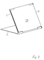
- the projection wall 1 according to FIG. 3 is turned on for transport the plate 2 folded and the plate 2 together with the Projection screen folded around the pivot axis 6 on the plate 3. As shown in Fig. 4, can be folded Transport the bracket easily.
- the projection screen 1 is through the plates 2 and 3 between which they is stored, protected from damage or dirt.
- a Plate 3 is in use in relation to the plate 2 folded back while the projection screen 1 is folded up. A height adjustment of the projection screen 1 is then omitted.
- the projection screen can also be used immediately be placed on the table surface, the Panels 2 and 3 opposite the projection screen 1 by approx Can be swiveled 90 ° backwards.
Landscapes
- Physics & Mathematics (AREA)
- General Physics & Mathematics (AREA)
- Overhead Projectors And Projection Screens (AREA)
Abstract
Description
- Figur 1 -
- eine perspektivische Ansicht einer Projektionswand mit ihrer Halterung im Gebrauchszustand;
- Figur 2 -
- einen Vertikalschnitt durch die Projektionswand gemäß Fig. 1;
- Figur 3 -
- eine perspektivische Ansicht der Projektionswand nach Fig. 1 im teilweise eingeklappten Zustand;
- Figur 4 -
- eine perspektivische Ansicht einer zum Transport zusammengeklappten Projektionswand nach Fig. 1.
Claims (7)
- Projektionswand (1) mit Halterung,
dadurch gekennzeichnet, daß die Projektionswand (1) zumindest starr ausgebildete Randbereiche (1a) aufweist, die einen zentralen Projektionsbereich (1b) umschließen und die über einen der Randbereiche (1a) um eine erste Schwenkachse (4) schwenkbeweglich und fixierbar an einer ersten Platte (2) angelenkt ist, die ihrerseits um eine zweite Schwenkachse (5) an einer zweiten Platte (3) schwenkbar und fixierbar angelenkt ist, und daß die Projektionswand (1) für ein Verstauen zwischen erster und zweiter Platte (2; 3) im zusammengeklappten Zustand ausgebildet ist. - Projektionswand nach Anspruch 1,
dadurch gekennzeichnet, daß die Projektionswand (1) für Frontseiten- und Rückseitenprojektion ausgebildet ist. - Projektionswand nach Anspruch 1 oder 2,
dadurch gekennzeichnet, daß die Projektionswand (1) als zumindest im wesentlichen starre Platte ausgebildet ist. - Projektionswand nach einem oder mehreren der Ansprüche 1 bis 3,
dadurch gekennzeichnet, daß der zentrale Projektionsbereich (1b) aus einem flächigen, textilen und gespannten Material besteht. - Projektionswand nach einem oder mehreren der Ansprüche 1 bis 4,
dadurch gekennzeichnet, daß die Schwenkachsen (4; 5) durch unmittelbar in Schwenkachsrichtung aneinander anschließende Ösenbereiche (1c; 2a; 1d; bzw. 3a; 2b; 3b) der verschiedenen Wand- oder Plattenelemente und diese axial durchsetzende Zapfen (6) gebildet sind. - Projektionswand nach einem oder mehreren der Ansprüche 1 bis 5,
dadurch gekennzeichnet, daß an mindestens einer Platte (2) ein Handgriff (2c) vorgesehen ist. - Projektionswand nach einem oder mehreren der Ansprüche 1 bis 6,
dadurch gekennzeichnet, daß Wand- und Plattenelemente mittels in Schwenkachsenrichtung wirkender, lösbarer Klemmverschraubungen in ihrer gegenseitigen Lage zueinander fixierbar sind.
Applications Claiming Priority (2)
| Application Number | Priority Date | Filing Date | Title |
|---|---|---|---|
| DE2001105482 DE10105482A1 (de) | 2001-02-07 | 2001-02-07 | Projektionswand mit Halterung |
| DE10105482 | 2001-02-07 |
Publications (1)
| Publication Number | Publication Date |
|---|---|
| EP1233300A1 true EP1233300A1 (de) | 2002-08-21 |
Family
ID=7673129
Family Applications (1)
| Application Number | Title | Priority Date | Filing Date |
|---|---|---|---|
| EP02002333A Withdrawn EP1233300A1 (de) | 2001-02-07 | 2002-01-31 | Projektionswand mit Halterung |
Country Status (2)
| Country | Link |
|---|---|
| EP (1) | EP1233300A1 (de) |
| DE (1) | DE10105482A1 (de) |
Cited By (1)
| Publication number | Priority date | Publication date | Assignee | Title |
|---|---|---|---|---|
| WO2015180646A1 (en) * | 2014-05-27 | 2015-12-03 | Mediatek Inc. | Projection display component and electronic device |
Citations (3)
| Publication number | Priority date | Publication date | Assignee | Title |
|---|---|---|---|---|
| DE2436633A1 (de) * | 1974-07-30 | 1976-02-12 | Horst Fehr | Zusammenklappbares rueckprojektionsgeraet fuer alle projektorarten |
| JPH10312024A (ja) * | 1997-03-13 | 1998-11-24 | Nikon Corp | プロジェクター |
| DE19900553A1 (de) * | 1999-01-09 | 2000-07-13 | Mechanische Weberei Gmbh | Stand-Lichtbildwand |
-
2001
- 2001-02-07 DE DE2001105482 patent/DE10105482A1/de not_active Withdrawn
-
2002
- 2002-01-31 EP EP02002333A patent/EP1233300A1/de not_active Withdrawn
Patent Citations (3)
| Publication number | Priority date | Publication date | Assignee | Title |
|---|---|---|---|---|
| DE2436633A1 (de) * | 1974-07-30 | 1976-02-12 | Horst Fehr | Zusammenklappbares rueckprojektionsgeraet fuer alle projektorarten |
| JPH10312024A (ja) * | 1997-03-13 | 1998-11-24 | Nikon Corp | プロジェクター |
| DE19900553A1 (de) * | 1999-01-09 | 2000-07-13 | Mechanische Weberei Gmbh | Stand-Lichtbildwand |
Non-Patent Citations (1)
| Title |
|---|
| PATENT ABSTRACTS OF JAPAN vol. 1999, no. 02 26 February 1999 (1999-02-26) * |
Cited By (2)
| Publication number | Priority date | Publication date | Assignee | Title |
|---|---|---|---|---|
| WO2015180646A1 (en) * | 2014-05-27 | 2015-12-03 | Mediatek Inc. | Projection display component and electronic device |
| US10136114B2 (en) | 2014-05-27 | 2018-11-20 | Mediatek Inc. | Projection display component and electronic device |
Also Published As
| Publication number | Publication date |
|---|---|
| DE10105482A1 (de) | 2002-08-08 |
Similar Documents
| Publication | Publication Date | Title |
|---|---|---|
| DE10241738B4 (de) | Präsentationsvorrichtung | |
| DE60012314T2 (de) | Warenschaustand | |
| DE20110717U1 (de) | Modularer Aufnahmekörper für ein Übungsgerät | |
| DE202015003174U1 (de) | Element, wie ein Tisch, eine Werkbank oder eine Sitzbank | |
| DE102022115231B3 (de) | Klappbares innenausstattungsteil | |
| DE202004015139U1 (de) | Transportable Projektionsvorrichtung | |
| DE10105482A1 (de) | Projektionswand mit Halterung | |
| DE202015007582U1 (de) | Klemm-Vorrichtung mit Hilfsfunktionen | |
| DE1772833B1 (de) | Bildschirm | |
| DE102020104568B4 (de) | Tisch mit Wandelement als Sicht- und/oder Akustikschutz | |
| DE102020109822A1 (de) | Modulare Präsentationsbaugruppe zur didaktischen Unterstützung bei Präsentationen | |
| DE3311973A1 (de) | Sportkinderwagen | |
| DE3815196C2 (de) | Schwenktafel | |
| DE4412877C2 (de) | Variabler, zusammenklappbarer Objekthalter | |
| DE3311600A1 (de) | Stativ | |
| DE102021112229A1 (de) | Rechteckige Tafel mit einem Tafelblatt | |
| DE10248987A1 (de) | Mobile Präsentationseinheit | |
| DE2058214A1 (de) | Informationstraeger zum Gebrauch bei einer Vorrichtung zur visuellen Wahrnehmbarmachung von Stehbildern | |
| DE102022124266A1 (de) | Eine zur magnetischen Verbindung mit wenigstens einer weiteren baugleichen Stellwand geeignete Stellwand | |
| DE10105481A1 (de) | Vorrichtung zur audiovisuellen Präsentation | |
| DE69427035T2 (de) | Konferenzgestell | |
| DE4003432C1 (en) | Mobile unit for storing transparencies - has folding support with raisable or lowerable projection position and folding storing section | |
| DE202026101627U1 (de) | Tisch | |
| DE202012008251U1 (de) | Zusammenklappbares Laufgitter | |
| DE102015105240B4 (de) | Sitzmöbel-Vorrichtung |
Legal Events
| Date | Code | Title | Description |
|---|---|---|---|
| PUAI | Public reference made under article 153(3) epc to a published international application that has entered the european phase |
Free format text: ORIGINAL CODE: 0009012 |
|
| AK | Designated contracting states |
Kind code of ref document: A1 Designated state(s): AT BE CH CY DE DK ES FI FR GB GR IE IT LI LU MC NL PT SE TR |
|
| AX | Request for extension of the european patent |
Free format text: AL;LT;LV;MK;RO;SI |
|
| 17P | Request for examination filed |
Effective date: 20030218 |
|
| AKX | Designation fees paid |
Designated state(s): AT BE CH CY DE DK ES FI FR GB GR IE IT LI LU MC NL PT SE TR |
|
| 17Q | First examination report despatched |
Effective date: 20030415 |
|
| RAP1 | Party data changed (applicant data changed or rights of an application transferred) |
Owner name: DDC DESIGN & DEVELOPMENT GMBH & CO. KG |
|
| STAA | Information on the status of an ep patent application or granted ep patent |
Free format text: STATUS: THE APPLICATION IS DEEMED TO BE WITHDRAWN |
|
| 18D | Application deemed to be withdrawn |
Effective date: 20031230 |