EP1236606B1 - Untersetzungsgetriebe, insbesondere zur Betätigung des Schneckenförderers eines Mischlastwagens und Hilfseinrichtungen - Google Patents
Untersetzungsgetriebe, insbesondere zur Betätigung des Schneckenförderers eines Mischlastwagens und Hilfseinrichtungen Download PDFInfo
- Publication number
- EP1236606B1 EP1236606B1 EP02004264A EP02004264A EP1236606B1 EP 1236606 B1 EP1236606 B1 EP 1236606B1 EP 02004264 A EP02004264 A EP 02004264A EP 02004264 A EP02004264 A EP 02004264A EP 1236606 B1 EP1236606 B1 EP 1236606B1
- Authority
- EP
- European Patent Office
- Prior art keywords
- reduction unit
- unit
- clutch
- reduction
- shaft gear
- Prior art date
- Legal status (The legal status is an assumption and is not a legal conclusion. Google has not performed a legal analysis and makes no representation as to the accuracy of the status listed.)
- Expired - Lifetime
Links
- 230000009467 reduction Effects 0.000 title claims abstract description 56
- 230000008878 coupling Effects 0.000 claims description 4
- 238000010168 coupling process Methods 0.000 claims description 4
- 238000005859 coupling reaction Methods 0.000 claims description 4
- 230000009471 action Effects 0.000 claims description 2
- 238000003780 insertion Methods 0.000 claims description 2
- 230000037431 insertion Effects 0.000 claims description 2
- 230000000717 retained effect Effects 0.000 claims description 2
- 230000004308 accommodation Effects 0.000 claims 1
- 239000012530 fluid Substances 0.000 claims 1
- 238000011144 upstream manufacturing Methods 0.000 claims 1
- 238000005259 measurement Methods 0.000 description 2
- 230000002860 competitive effect Effects 0.000 description 1
- 230000007423 decrease Effects 0.000 description 1
- 239000004459 forage Substances 0.000 description 1
- 238000010438 heat treatment Methods 0.000 description 1
- 244000144972 livestock Species 0.000 description 1
- 239000000463 material Substances 0.000 description 1
- 238000012986 modification Methods 0.000 description 1
- 230000004048 modification Effects 0.000 description 1
Images

Classifications
-
- B—PERFORMING OPERATIONS; TRANSPORTING
- B60—VEHICLES IN GENERAL
- B60K—ARRANGEMENT OR MOUNTING OF PROPULSION UNITS OR OF TRANSMISSIONS IN VEHICLES; ARRANGEMENT OR MOUNTING OF PLURAL DIVERSE PRIME-MOVERS IN VEHICLES; AUXILIARY DRIVES FOR VEHICLES; INSTRUMENTATION OR DASHBOARDS FOR VEHICLES; ARRANGEMENTS IN CONNECTION WITH COOLING, AIR INTAKE, GAS EXHAUST OR FUEL SUPPLY OF PROPULSION UNITS IN VEHICLES
- B60K25/00—Auxiliary drives
- B60K25/06—Auxiliary drives from the transmission power take-off
Definitions
- the present invention relates to a reduction unit particularly for actuating screw feeders of mixing trucks and auxiliary elements.
- the screw feeders arranged inside the mixing truck shred and mix, by means of cutting edges distributed on the screw feeders, the forage intended to feed livestock.
- a desiling cutter is provided, which is designed to remove the product from the silos, facilitating its fall into the mixing truck.
- the desiling operation is particularly dangerous, because it occurs while the screw feeders are moving since there is a nondetachable functional connection and therefore the actuation of the desiling cutter automatically entails the actuation of the screw feeders.
- DE 1 068 049 and DE 1 081 265 both showing the features of the preamble of claim 1 disclose reduction units comprising a parallel shaft gear unit, with output shafts selectively coupled to an input shaft by clutches inside the parallel shaft gear unit.
- EP-A-0 357 580 discloses a coupling for a power take-off shaft of a tractor comprising a hydraulic clutch and a reduction gear.
- the aim of the present invention is to eliminate the drawbacks noted above, by providing a reduction unit particularly for actuating the screw feeders of mixing trucks and auxiliary elements that allows to uncouple the actuation of the screw feeders from the actuation of the auxiliary elements.
- an object of the invention is to provide a reduction unit that while having substantially improved characteristics maintains in its general features the classical structure of a reduction unit for mixing trucks.
- Another object of the present invention is to provide a reduction unit particularly for actuating screw feeders of mixing trucks and auxiliary elements that, for its particular constructive characteristics, is capable of giving the greatest assurances of reliability and safety in use.
- Another object of the present invention is to provide a reduction unit that can be easily obtained starting from commonly commercially available elements and materials and is further competitive from a merely economical standpoint.
- a reduction unit particularly for actuating screw feeders of mixing trucks and auxiliary elements comprising a parallel shaft gear unit which is associable with the power take-off of a tractor and is operatively connected to a reduction unit body of the reduction unit, said parallel shaft gear unit forming couplings for the connection of auxiliary elements and said reduction unit body being associable with the screw feeders of a mixing truck, characterized in that it comprises a clutch-type disengagement unit between said parallel shaft gear unit and said reduction unit body.
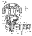
- the reduction unit particularly for actuating screw feeders of mixing trucks and auxiliary elements comprises a parallel shaft gear unit 2 which has, inside a box-like enclosure 3, an input gear 4 keyed on an input shaft 5 which can be connected to the power take-off of a tractor and the like.
- the input gear 4 meshes with a first driven gear 6, which is keyed on a driven shaft 7 rotatably supported by the box-like enclosure of the parallel shaft gear unit.
- the input gear 4 meshes with a second driven gear 10, which has internal splined profiles 11 for the connection of auxiliary elements, such as for example the pumps, not shown in the drawing, which are used to actuate the several hydraulic services of the mixing truck.
- auxiliary elements such as for example the pumps, not shown in the drawing, which are used to actuate the several hydraulic services of the mixing truck.
- the driven shaft 7 is operatively associated with a reduction unit body, which is constituted by a two-stage epicyclic reduction unit, generally designated by the reference numeral 20.
- the particularity of the invention consists in that between the reduction unit body 20 and the parallel shaft gear unit 2 a clutch-type disengagement unit is interposed, generally designated by the reference numeral 21, which comprises a multiple-disk oil-bath clutch, known per se.
- the clutch 21 is accommodated in a casing 22, which can be monolithic with the box-like body 3 of the parallel shaft gear unit, as shown in the upper part of the drawing of Figure 1 or can optionally be constituted by a separate element 22a, as shown schematically in the lower part of the drawing of Figure 1.
- the clutch has a plurality of driving disks 23, which are turned by a bell 24 provided with slots for engaging driving tenons 25 defined by the disks 23.
- the driven disks 23 turn a hub 27, which rotates rigidly with the shaft of a sun gear 28, which constitutes in practice the input in the epicyclic reduction unit body 20.
- a piston 30 is provided which, in cooperation with the bell 24, delimits a chamber 31, which is connected to branching connectors 32 defined in the bell and connected to an axial duct 33 formed in the driven shaft 7 of the parallel shaft gear unit which ends with radial channels 34 that lead into a manifold 35 defined in a connector 36 located at the end of the driven shaft 7, to which it is possible to connect, for example, measurement instruments and the like.
- the actuation oil is conveyed to the connector 36 and, by means of the manifold 35, is sent into the duct 33 and from there to branching connectors 32 to reach the chamber 31 in order to actuate the piston 30.
- Two O-rings 37 are provided which avoid the escape of oil inside the reduction unit, and between the manifold 35 and the shaft 7 rotating seals 41 are provided. Any small leaks from said seals are conveyed to a drainage system 42 and returned to the reservoir.
- Oil retainers 39 and 40 are also provided which prevent the possible small leaks from spilling respectively toward the casing of the reduction unit or toward the outside.
- This system allows to use, for the actuation oil, an external source that is independent of the casing.
- a braking device is provided, generally designated by the reference numeral 60, which is designed to keep the screw feeders motionless while the clutch is disengaged.
- the braking device 60 has a disk 61 mounted on the hub 27 and a pair of counter plates 62 whose rotation is prevented because they are associated with the box-like body 22 by means of tenons 63.
- the axial play between the disk 61 and the counter plates 62 is conveniently reduced with respect to the play of the clutch, and therefore a braking torque is generated on the hub 27 which contrasts the driving torque, thus avoiding the unintentional movement of the screw feeders.
- Spacing pins 70 are also provided which can be connected directly on the hydraulic circuit for supplying the pressurized oil to the clutch, so that the same pressure that is sent to engage the clutch automatically causes the insertion of the spacing pins and accordingly the disengagement of the braking element.
Landscapes
- Engineering & Computer Science (AREA)
- Chemical & Material Sciences (AREA)
- Combustion & Propulsion (AREA)
- Transportation (AREA)
- Mechanical Engineering (AREA)
- Screw Conveyors (AREA)
- Hydraulic Clutches, Magnetic Clutches, Fluid Clutches, And Fluid Joints (AREA)
- Mixers Of The Rotary Stirring Type (AREA)
- Gear Transmission (AREA)
Claims (16)
- Untersetzungsgetriebe (1), insbesondere zur Betätigung von Schneckenförderern von Mischlastwagen und Hilfseinrichtungen, mit einem Parallelgetriebe (2), das mit dem Abtrieb einer Zugmaschine verbunden werden kann, und einsatzbereit mit dem Untersetzungsgetriebe-Gehäuse (20) des Untersetzungsgetriebes verbunden ist, wobei das Parallelgetriebe (2) Verbindungen (10, 11) für den Anschluss von Hilfseinrichtungen bildet, und das Untersetzungsgetriebe-Gehäuse (20) mit den Schneckenförderern eines Mischlastwagens verbunden werden kann, dadurch gekennzeichnet, dass es eine kupplungsartige Auskupplung (21) zwischen dem Parallelgetriebe (2) und dem Untersetzungsgetriebe-Gehäuse (20) besitzt.
- Untersetzungsgetriebe (1) nach Anspruch 1, dadurch gekennzeichnet, dass es an dem Parallelgetriebe (2) vor der kupplungsartigen Auskupplung (21) in Bewegungseingangsrichtung ein zweites Antriebsrad (10) mit Keilprofilen (11) für den Anschluss von Hilfseinrichtungen besitzt.
- Untersetzungsgetriebe (1) nach den vorhergehenden Ansprüchen, dadurch gekennzeichnet, dass das Untersetzungsgetriebe-Gehäuse aus einem zweistufigen, epizyklischen Untersetzungsgetriebe (20) besteht.
- Untersetzungsgetriebe (1) nach einem oder mehreren der vorhergehenden Ansprüche, dadurch gekennzeichnet, dass es ein Gehäuse (22) für die Unterbringung der kupplungsartigen Auskupplung (21) besitzt, das mit einer kastenartigen Einfassung (3) des Parallelgetriebes (2) monolithisch ausgebildet ist.
- Untersetzungsgetriebe (1) nach Anspruch 4, dadurch gekennzeichnet, dass es für die Unterbringung der kupplungsartigen Auskupplung (21) ein separates Element (22a) besitzt, das zwischen die kastenförmige Einfassung (3) des Parallelgetriebes (2) und das Untersetzungsgetriebe-Gehäuse (20) eingeschoben werden kann.
- Untersetzungsgetriebe (1) nach Anspruch 3, dadurch gekennzeichnet, dass die kupplungsartige Auskupplung (21) eine Muffe (24) besitzt, die sich fest mit der Antriebswelle (7) des Parallelgetriebes (2) dreht, und Schlitze für die gleitende Aufnahme von Antriebszapfen (25) besitzt, die sich an Treibscheiben befinden, welche zwischen den angetriebenen Scheiben (23) eingeschoben wurden, die sich fest mit einer Nabe (27) drehen, welche wiederum an der Welle des Laufkranzes (28) des epizyklischen Untersetzungsgetriebes (20) verkeilt sind.
- Untersetzungsgetriebe (1) nach Anspruch 6, dadurch gekennzeichnet, dass es Elemente für die Betätigung der kupplungsartigen Auskupplung (21) besitzt, welche einen Kolben (30) besitzen, der zusammen mit der Muffe (24) eine Kammer (31) bildet, welche mit einer Druckölquelle verbunden ist.
- Untersetzungsgetriebe (1) nach Anspruch 7, dadurch gekennzeichnet, dass es sich verzweigende Stecker (32) besitzt, die mit der Muffe (24) verbunden sind, und aus einem axialen Kanal (33) herausragen, der in der Antriebswelle (7) des Parallelgetriebes (2) gebildet wird, wobei der axiale Kanal (33) in radialen Kanälen (34) endet, welche in einen Verteiler (35) führen, der durch einen Stecker (36) gebildet wird, welcher sich am Ende der Antriebswelle (7) befindet, wobei der Verteiler (35) mit einer Druckflüssigkeitsquelle verbunden ist.
- Untersetzungsgetriebe (1) nach Anspruch 8, dadurch gekennzeichnet, dass es zwei O-Ringe (37) besitzt, die mit der Antriebswelle (7) in dem Bereich verbunden sind, in dem die Stecker (32) angeschlossen sind, sowie zwei drehbare Dichtungen (41), welche in dem Bereich gebildet werden, in dem der Verteiler (35) angeschlossen ist.
- Untersetzungsgetriebe (1) nach Anspruch 9, dadurch gekennzeichnet, dass es an den Seiten der drehbaren Dichtungen (41) Ölrückhaltevorrichtungen (39, 40) besitzt, welche einen Ablaufbereich begrenzen, der sich außerhalb der drehbaren Dichtungen (41) befindet.
- Untersetzungsgetriebe (1) nach einem oder mehreren der vorhergehenden Ansprüche 6 bis 10, dadurch gekennzeichnet, dass es in der Muffe (24) eine Gegenplatte (50) besitzt, die durch einen Haltering (51) gesichert wird, welcher die kupplungsartige Auskupplung (21) ausgleicht.
- Untersetzungsgetriebe (1) nach einem oder mehreren der vorhergehenden Ansprüche 6 bis 11, dadurch gekennzeichnet, dass es eine Bremsvorrichtung (60) besitzt, welche auf die Welle des Laufkranzes (28) wirkt, um die Betätigung der Schneckenförderer zu verhindern, wenn sich die kupplungsartige Auskupplung (2) in der ausgekuppelten Position befindet.
- Untersetzungsgetriebe (1) nach Anspruch 12, dadurch gekennzeichnet, dass es eine Scheibe (61) besitzt, die an der Nabe (27) montiert und zwischen einem Paar Gegenplatten (62) angeordnet sind, welche mit Zapfen versehen sind, die in die Innenfläche der kastenartigen Einfassung (3) der kupplungsartigen Auskupplung (2) eingreifen können.
- Untersetzungsgetriebe (1) nach Anspruch 13, dadurch gekennzeichnet, dass die Scheibe (61) und die Gegenplatte (62) in einem Abstand zueinander angeordnet sind, wobei mit einer zugewandten Fläche der Bremsvorgang gestoppt wird, wenn sich das Öl erwärmt.
- Untersetzungsgetriebe (1) nach Anspruch 14, dadurch gekennzeichnet, dass es Elemente (64) besitzt, mittels derer die Gegenplatten (62) durch Druck an die Scheibe (61) geklemmt werden, wobei die Elemente durch mindestens einen Distanzstift (70), der durch den gleichen Hydraulikkreis wie für den Einschub der kupplungsartigen Auskupplung (21) betätigt wird, deaktiviert werden können.
- Untersetzungsgetriebe (1) nach Anspruch 15, dadurch gekennzeichnet, dass die Elemente für das gegenseitige Festklemmen der Gegenplatten (62) an der Scheibe (61) aus elastischen Stoßelementen (64) bestehen, welche zwischen einer der Gegenplatten (62) und dem breiteren Ende eines Stiftes (66) wirken, der mit dem anderen Ende der Gegenplatte (62) verbunden ist, und durch die Gegenplatte (62) führt.
Applications Claiming Priority (2)
| Application Number | Priority Date | Filing Date | Title |
|---|---|---|---|
| ITMI010436 | 2001-03-02 | ||
| IT2001MI000436A ITMI20010436A1 (it) | 2001-03-02 | 2001-03-02 | Gruppo riduttore particolarmente per l'azionamento delle coclee di carri miscelatori e di elementi ausiliari |
Publications (3)
| Publication Number | Publication Date |
|---|---|
| EP1236606A2 EP1236606A2 (de) | 2002-09-04 |
| EP1236606A3 EP1236606A3 (de) | 2003-03-05 |
| EP1236606B1 true EP1236606B1 (de) | 2005-01-05 |
Family
ID=11447097
Family Applications (1)
| Application Number | Title | Priority Date | Filing Date |
|---|---|---|---|
| EP02004264A Expired - Lifetime EP1236606B1 (de) | 2001-03-02 | 2002-02-27 | Untersetzungsgetriebe, insbesondere zur Betätigung des Schneckenförderers eines Mischlastwagens und Hilfseinrichtungen |
Country Status (4)
| Country | Link |
|---|---|
| EP (1) | EP1236606B1 (de) |
| AT (1) | ATE286460T1 (de) |
| DE (1) | DE60202494T2 (de) |
| IT (1) | ITMI20010436A1 (de) |
Families Citing this family (1)
| Publication number | Priority date | Publication date | Assignee | Title |
|---|---|---|---|---|
| CN215805832U (zh) * | 2021-09-01 | 2022-02-11 | 三一汽车起重机械有限公司 | 取力传动装置和起重机 |
Citations (3)
| Publication number | Priority date | Publication date | Assignee | Title |
|---|---|---|---|---|
| DE1068049B (de) * | 1959-10-29 | |||
| DE1081265B (de) * | 1958-06-06 | 1960-05-05 | Wilhelm Stiebel | Zapfwellenzwischengetriebe fuer land- und forstwirtschaftliche Geraete |
| EP0357580A2 (de) * | 1988-08-31 | 1990-03-07 | Valmet Oy | Kupplung für Nebenantriebswelle |
Family Cites Families (5)
| Publication number | Priority date | Publication date | Assignee | Title |
|---|---|---|---|---|
| US3658303A (en) * | 1969-10-17 | 1972-04-25 | Funk Mfg Co | Drive mechanism for concrete mixer |
| US3749372A (en) * | 1972-01-27 | 1973-07-31 | Funk Mfg Co | Yieldable support means and drive mechanism for concrete mixer drums |
| US4546661A (en) * | 1984-01-09 | 1985-10-15 | Dana Corporation | Countershaft driven power take-off |
| IT1208047B (it) * | 1987-05-21 | 1989-06-01 | Comer Spa | Struttura di innesto di sicurezza per la connessione di macchine con organi in movimento ad un gruppo motore. |
| RU2176229C1 (ru) * | 2000-09-26 | 2001-11-27 | Государственное унитарное предприятие "Научно-исследовательский институт полимерных материалов" | Установка для смешения и формования |
-
2001
- 2001-03-02 IT IT2001MI000436A patent/ITMI20010436A1/it unknown
-
2002
- 2002-02-27 AT AT02004264T patent/ATE286460T1/de not_active IP Right Cessation
- 2002-02-27 EP EP02004264A patent/EP1236606B1/de not_active Expired - Lifetime
- 2002-02-27 DE DE60202494T patent/DE60202494T2/de not_active Expired - Lifetime
Patent Citations (3)
| Publication number | Priority date | Publication date | Assignee | Title |
|---|---|---|---|---|
| DE1068049B (de) * | 1959-10-29 | |||
| DE1081265B (de) * | 1958-06-06 | 1960-05-05 | Wilhelm Stiebel | Zapfwellenzwischengetriebe fuer land- und forstwirtschaftliche Geraete |
| EP0357580A2 (de) * | 1988-08-31 | 1990-03-07 | Valmet Oy | Kupplung für Nebenantriebswelle |
Also Published As
| Publication number | Publication date |
|---|---|
| EP1236606A2 (de) | 2002-09-04 |
| DE60202494D1 (de) | 2005-02-10 |
| EP1236606A3 (de) | 2003-03-05 |
| ATE286460T1 (de) | 2005-01-15 |
| DE60202494T2 (de) | 2005-06-02 |
| ITMI20010436A1 (it) | 2002-09-02 |
Similar Documents
| Publication | Publication Date | Title |
|---|---|---|
| US5261517A (en) | Multi-disk clutch | |
| CA1083505A (en) | Dump valve for wet clutch | |
| EP2922721B1 (de) | Mehrstufiger leitungsstartantrieb für einen ackerschlepper | |
| US8161834B2 (en) | Transmission with power take-off drive | |
| EP0987459A3 (de) | Mehrscheiben-Reibeinrichtung mit steuerbarer Zwangsschmierung | |
| US8984973B1 (en) | Multiple speed power take off | |
| US3507372A (en) | Hydraulic clutch and brake system | |
| US3041884A (en) | Power take-off drive for tractors | |
| US6470658B1 (en) | Agricultural implement, in particular a mowing machine | |
| US3698524A (en) | I.p.t.o brake unit | |
| CA1099953A (en) | Differential with variable torque means | |
| US4464137A (en) | Clutch mechanism | |
| EP1236606B1 (de) | Untersetzungsgetriebe, insbesondere zur Betätigung des Schneckenförderers eines Mischlastwagens und Hilfseinrichtungen | |
| GB2152605A (en) | Countershaft driven power take-off | |
| US6523429B2 (en) | Multi speed power take off | |
| EP1634758B1 (de) | Getriebeeinheit insbesondere für den Antrieb der Schraubenförderer und Hilfseinrichtungen von Mischwagen | |
| US6131714A (en) | Auxiliary drive for utility vehicle and method of operation thereof | |
| GB1437608A (en) | Variable speed drive unit | |
| US5701738A (en) | Mechanical disconnect for variable speed hydrostatic transmission | |
| US6845831B2 (en) | PTO shaft brake | |
| EP2730446B1 (de) | Mehrgängige Zapfwelle | |
| US5161658A (en) | Viscous coupling | |
| EP0332850B1 (de) | Antriebs-Baugruppe und selbstfahrender Feldhäcksler mit einer solchen Baugruppe | |
| SU1761559A1 (ru) | Привод отбора мощности | |
| US3247738A (en) | Transmission |
Legal Events
| Date | Code | Title | Description |
|---|---|---|---|
| PUAI | Public reference made under article 153(3) epc to a published international application that has entered the european phase |
Free format text: ORIGINAL CODE: 0009012 |
|
| AK | Designated contracting states |
Kind code of ref document: A2 Designated state(s): AT BE CH CY DE DK ES FI FR GB GR IE IT LI LU MC NL PT SE TR |
|
| AX | Request for extension of the european patent |
Free format text: AL;LT;LV;MK;RO;SI |
|
| PUAL | Search report despatched |
Free format text: ORIGINAL CODE: 0009013 |
|
| AK | Designated contracting states |
Kind code of ref document: A3 Designated state(s): AT BE CH CY DE DK ES FI FR GB GR IE IT LI LU MC NL PT SE TR |
|
| AX | Request for extension of the european patent |
Extension state: AL LT LV MK RO SI |
|
| RIC1 | Information provided on ipc code assigned before grant |
Ipc: 7F 16H 37/04 B Ipc: 7B 60K 17/28 B Ipc: 7F 16H 1/28 B Ipc: 7F 16H 1/06 B Ipc: 7B 60K 25/06 A Ipc: 7F 16H 37/00 B |
|
| 17P | Request for examination filed |
Effective date: 20030901 |
|
| TPAC | Observations filed by third parties |
Free format text: ORIGINAL CODE: EPIDOSNTIPA |
|
| AKX | Designation fees paid |
Designated state(s): AT BE CH CY DE DK ES FI FR GB GR IE IT LI LU MC NL PT SE TR |
|
| 17Q | First examination report despatched |
Effective date: 20040116 |
|
| RAP1 | Party data changed (applicant data changed or rights of an application transferred) |
Owner name: COMER INDUSTRIES S.P.A. |
|
| GRAP | Despatch of communication of intention to grant a patent |
Free format text: ORIGINAL CODE: EPIDOSNIGR1 |
|
| RIC1 | Information provided on ipc code assigned before grant |
Ipc: 7A 01B 71/06 B Ipc: 7F 16H 1/06 B Ipc: 7F 16H 37/04 B Ipc: 7B 60K 17/28 B Ipc: 7B 60K 25/06 A Ipc: 7F 16H 1/28 B Ipc: 7F 16H 37/00 B |
|
| RIC1 | Information provided on ipc code assigned before grant |
Ipc: 7F 16H 37/04 B Ipc: 7B 60K 17/28 B Ipc: 7B 60K 25/06 A Ipc: 7F 16H 37/00 B Ipc: 7F 16H 1/28 B Ipc: 7A 01B 71/06 B Ipc: 7F 16H 1/06 B |
|
| GRAA | (expected) grant |
Free format text: ORIGINAL CODE: 0009210 |
|
| GRAS | Grant fee paid |
Free format text: ORIGINAL CODE: EPIDOSNIGR3 |
|
| AK | Designated contracting states |
Kind code of ref document: B1 Designated state(s): AT BE CH CY DE DK ES FI FR GB GR IE IT LI LU MC NL PT SE TR |
|
| PG25 | Lapsed in a contracting state [announced via postgrant information from national office to epo] |
Ref country code: CH Free format text: LAPSE BECAUSE OF FAILURE TO SUBMIT A TRANSLATION OF THE DESCRIPTION OR TO PAY THE FEE WITHIN THE PRESCRIBED TIME-LIMIT Effective date: 20050105 Ref country code: LI Free format text: LAPSE BECAUSE OF FAILURE TO SUBMIT A TRANSLATION OF THE DESCRIPTION OR TO PAY THE FEE WITHIN THE PRESCRIBED TIME-LIMIT Effective date: 20050105 Ref country code: FI Free format text: LAPSE BECAUSE OF FAILURE TO SUBMIT A TRANSLATION OF THE DESCRIPTION OR TO PAY THE FEE WITHIN THE PRESCRIBED TIME-LIMIT Effective date: 20050105 Ref country code: TR Free format text: LAPSE BECAUSE OF FAILURE TO SUBMIT A TRANSLATION OF THE DESCRIPTION OR TO PAY THE FEE WITHIN THE PRESCRIBED TIME-LIMIT Effective date: 20050105 Ref country code: BE Free format text: LAPSE BECAUSE OF FAILURE TO SUBMIT A TRANSLATION OF THE DESCRIPTION OR TO PAY THE FEE WITHIN THE PRESCRIBED TIME-LIMIT Effective date: 20050105 Ref country code: AT Free format text: LAPSE BECAUSE OF FAILURE TO SUBMIT A TRANSLATION OF THE DESCRIPTION OR TO PAY THE FEE WITHIN THE PRESCRIBED TIME-LIMIT Effective date: 20050105 |
|
| REG | Reference to a national code |
Ref country code: GB Ref legal event code: FG4D |
|
| REG | Reference to a national code |
Ref country code: CH Ref legal event code: EP |
|
| REG | Reference to a national code |
Ref country code: IE Ref legal event code: FG4D |
|
| REF | Corresponds to: |
Ref document number: 60202494 Country of ref document: DE Date of ref document: 20050210 Kind code of ref document: P |
|
| PG25 | Lapsed in a contracting state [announced via postgrant information from national office to epo] |
Ref country code: LU Free format text: LAPSE BECAUSE OF NON-PAYMENT OF DUE FEES Effective date: 20050227 Ref country code: CY Free format text: LAPSE BECAUSE OF FAILURE TO SUBMIT A TRANSLATION OF THE DESCRIPTION OR TO PAY THE FEE WITHIN THE PRESCRIBED TIME-LIMIT Effective date: 20050227 |
|
| PG25 | Lapsed in a contracting state [announced via postgrant information from national office to epo] |
Ref country code: IE Free format text: LAPSE BECAUSE OF NON-PAYMENT OF DUE FEES Effective date: 20050228 Ref country code: MC Free format text: LAPSE BECAUSE OF NON-PAYMENT OF DUE FEES Effective date: 20050228 |
|
| PG25 | Lapsed in a contracting state [announced via postgrant information from national office to epo] |
Ref country code: GR Free format text: LAPSE BECAUSE OF FAILURE TO SUBMIT A TRANSLATION OF THE DESCRIPTION OR TO PAY THE FEE WITHIN THE PRESCRIBED TIME-LIMIT Effective date: 20050405 Ref country code: SE Free format text: LAPSE BECAUSE OF FAILURE TO SUBMIT A TRANSLATION OF THE DESCRIPTION OR TO PAY THE FEE WITHIN THE PRESCRIBED TIME-LIMIT Effective date: 20050405 Ref country code: DK Free format text: LAPSE BECAUSE OF FAILURE TO SUBMIT A TRANSLATION OF THE DESCRIPTION OR TO PAY THE FEE WITHIN THE PRESCRIBED TIME-LIMIT Effective date: 20050405 |
|
| PG25 | Lapsed in a contracting state [announced via postgrant information from national office to epo] |
Ref country code: ES Free format text: LAPSE BECAUSE OF FAILURE TO SUBMIT A TRANSLATION OF THE DESCRIPTION OR TO PAY THE FEE WITHIN THE PRESCRIBED TIME-LIMIT Effective date: 20050416 |
|
| REG | Reference to a national code |
Ref country code: CH Ref legal event code: PL |
|
| PLBE | No opposition filed within time limit |
Free format text: ORIGINAL CODE: 0009261 |
|
| STAA | Information on the status of an ep patent application or granted ep patent |
Free format text: STATUS: NO OPPOSITION FILED WITHIN TIME LIMIT |
|
| REG | Reference to a national code |
Ref country code: IE Ref legal event code: MM4A |
|
| ET | Fr: translation filed | ||
| 26N | No opposition filed |
Effective date: 20051006 |
|
| REG | Reference to a national code |
Ref country code: GB Ref legal event code: FG4D |
|
| PG25 | Lapsed in a contracting state [announced via postgrant information from national office to epo] |
Ref country code: PT Free format text: LAPSE BECAUSE OF NON-PAYMENT OF DUE FEES Effective date: 20050605 |
|
| REG | Reference to a national code |
Ref country code: FR Ref legal event code: PLFP Year of fee payment: 14 |
|
| REG | Reference to a national code |
Ref country code: FR Ref legal event code: PLFP Year of fee payment: 15 |
|
| REG | Reference to a national code |
Ref country code: FR Ref legal event code: PLFP Year of fee payment: 16 |
|
| REG | Reference to a national code |
Ref country code: FR Ref legal event code: PLFP Year of fee payment: 17 |
|
| PGFP | Annual fee paid to national office [announced via postgrant information from national office to epo] |
Ref country code: NL Payment date: 20190227 Year of fee payment: 18 |
|
| PGFP | Annual fee paid to national office [announced via postgrant information from national office to epo] |
Ref country code: IT Payment date: 20181218 Year of fee payment: 18 Ref country code: DE Payment date: 20190212 Year of fee payment: 18 Ref country code: GB Payment date: 20190208 Year of fee payment: 18 |
|
| PGFP | Annual fee paid to national office [announced via postgrant information from national office to epo] |
Ref country code: FR Payment date: 20190208 Year of fee payment: 18 |
|
| REG | Reference to a national code |
Ref country code: DE Ref legal event code: R119 Ref document number: 60202494 Country of ref document: DE |
|
| REG | Reference to a national code |
Ref country code: NL Ref legal event code: MM Effective date: 20200301 |
|
| GBPC | Gb: european patent ceased through non-payment of renewal fee |
Effective date: 20200227 |
|
| PG25 | Lapsed in a contracting state [announced via postgrant information from national office to epo] |
Ref country code: NL Free format text: LAPSE BECAUSE OF NON-PAYMENT OF DUE FEES Effective date: 20200301 |
|
| PG25 | Lapsed in a contracting state [announced via postgrant information from national office to epo] |
Ref country code: GB Free format text: LAPSE BECAUSE OF NON-PAYMENT OF DUE FEES Effective date: 20200227 Ref country code: DE Free format text: LAPSE BECAUSE OF NON-PAYMENT OF DUE FEES Effective date: 20200901 Ref country code: FR Free format text: LAPSE BECAUSE OF NON-PAYMENT OF DUE FEES Effective date: 20200229 |
|
| PG25 | Lapsed in a contracting state [announced via postgrant information from national office to epo] |
Ref country code: IT Free format text: LAPSE BECAUSE OF NON-PAYMENT OF DUE FEES Effective date: 20200227 |